MICROFILM
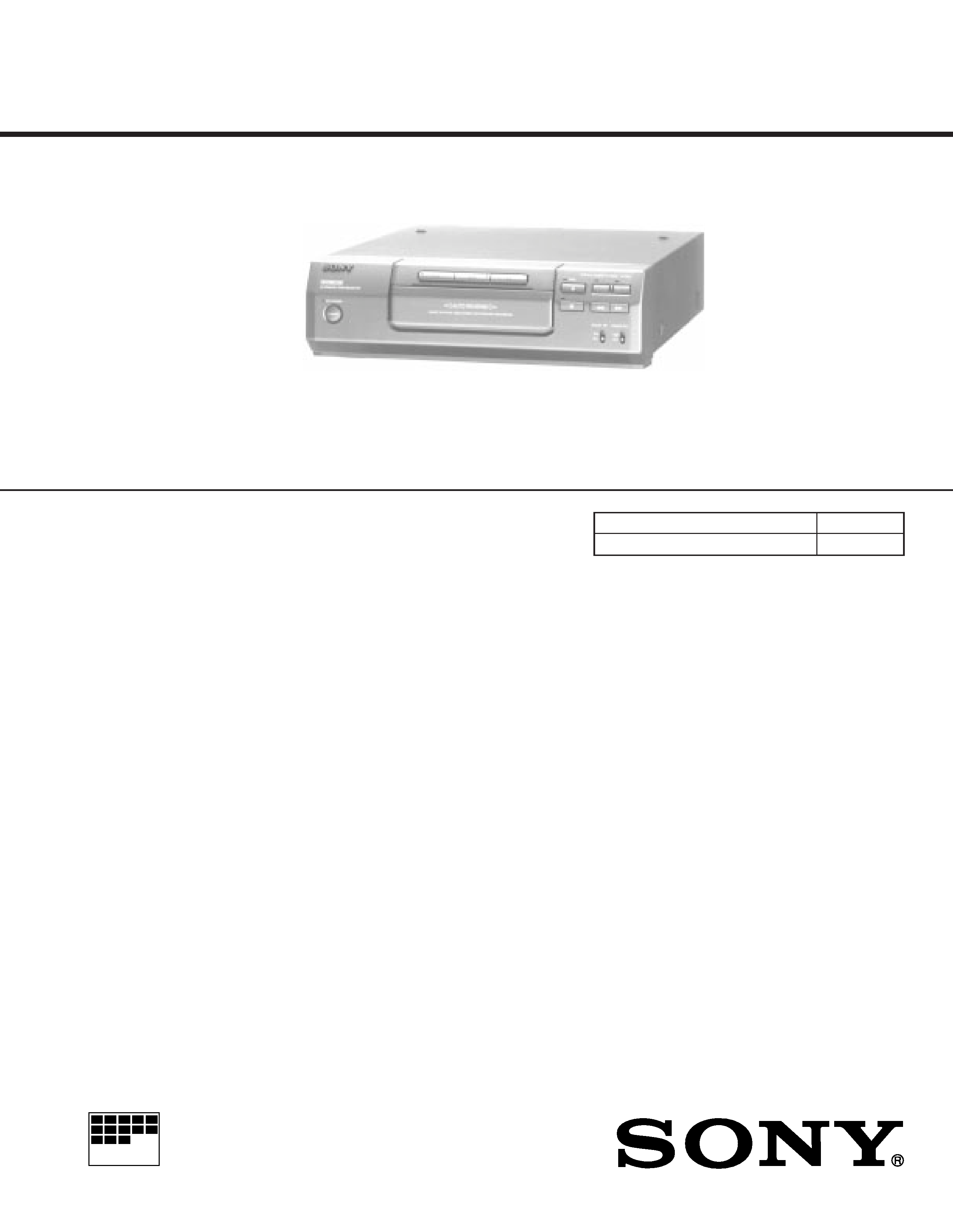
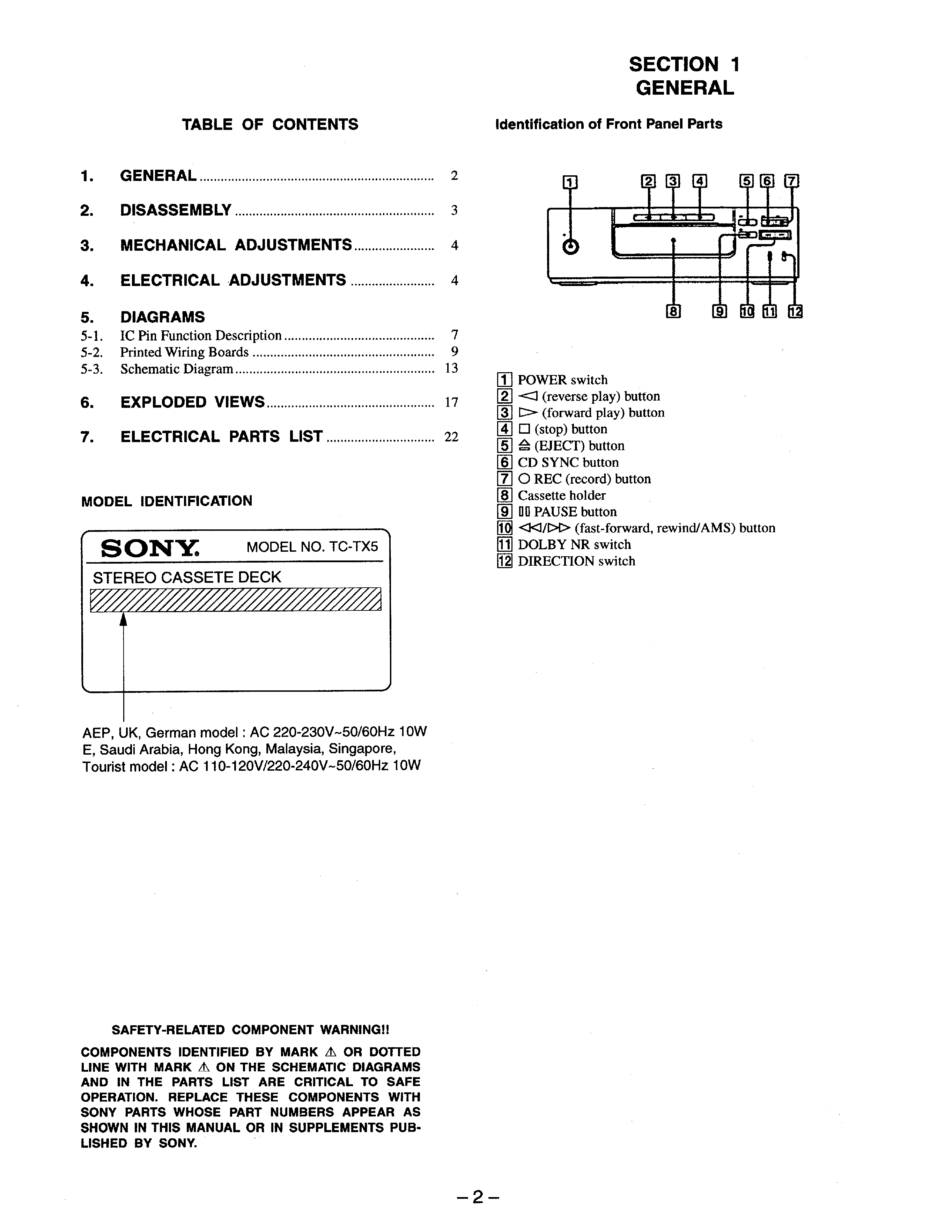
TC-TX5
STEREO CASSETTE DECK
AEP Model
UK Model
E Model
Tourist Model
SERVICE MANUAL
Dolby noise reduction manufactured under
license from Dolby Laboratories Licensing
Corporation.
"DOLBY" and the double-D symbol
a are
trademarks of Dolby Laboratories Licensing
Corporation.
Model Name Using Similar Mechanism
TC-S1
Tape Transport Mechanism Type
TCM-9700HLD
SPECIFICATIONS
Recording system
4-track 2-channel stereo
Frequency response
(DOLBY NR OFF)
30 14,000 Hz (±3 dB), using
Sony TYPE I cassette
30 15,000 Hz (±3 dB), using
Sony TYPE II cassette
Wow and flutter
±0.15% W. Peak (IEC)
0.1% W. RMS (NAB)
±0.2% W. Peak (DIN)
Input
TAPE IN (phono jacks):
impedance 47 kilohms
Output
TAPE OUT (phono jacks):
voltage 550 mV
impedance 47 kilohms
General
Power requirements
AEP, UK, Germany:
220 230V AC, 50/60 Hz
Other countries:
110 120V or 220 240 V AC,
50/60Hz Adjustable with the
voltage selector
Power consumption
10 W
Dimensions
Approx. 280
× 85 × 360 mm
(111/8
× 33/8 × 141/4 in) (w/h/d)
incl. projecting parts and controls
Mass
Approx. 3.7 kg (8 lb 3 oz)
Supplied accessories: Audio connecting cord (2)
AU BUS connecting cord (1)
Design and specifications are subject to change without
notice.
3
SECTION 2
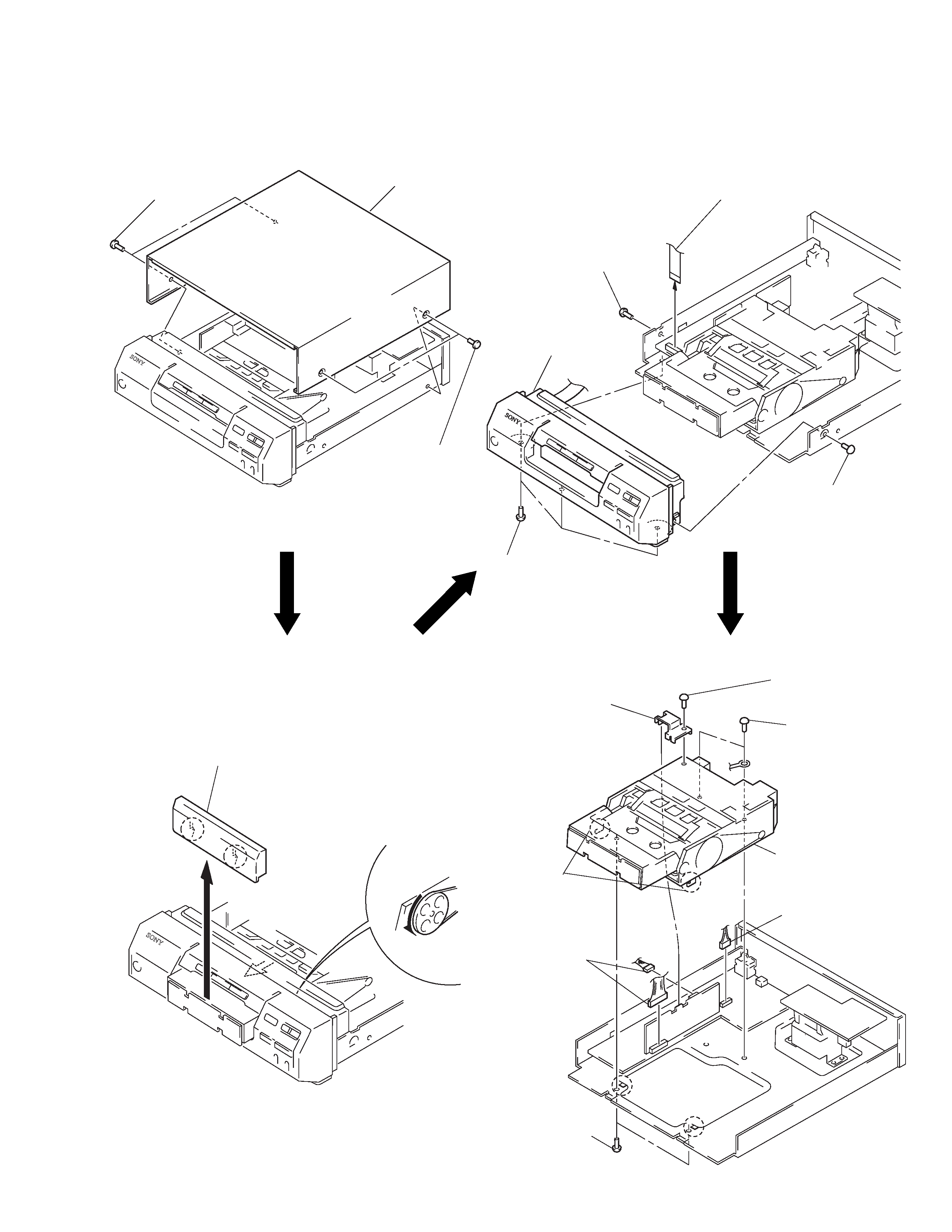
DISASSEMBLY
Note: Follow the disassembly procedure in the numerical order given.
CASE
FRONT PANEL SECTION
LOADING PANEL
MECHANISM DECK
2 Remove the loading panel
to direction of the arrow B.
B
1 Rotate the gear
to direction of
the arrow A.
1 two screws
(BVTT2.6
× 8)
3 two screws
(BV3
× 8)
2 bracket
7 mechanism deck
5 connector
(CN804)
4 four
screws
(BV3
× 8)
6 two
claws
5 two
connectors
(CN351, 803)
1 two screws
(CASE 3 TP2)
2 case
1 two screws
(CASE 3 TP2)
1 screw
(BV3
× 8)
2 flat wire
(CN802)
3 front panel section
1 screw
(BV3
× 8)
1 three screws
(BV3
× 8)
A
4
PRECAUTION
1. Clean the following parts with a denatured-alcohol-moistened
swab:
record/playback/earth head pinch roller
rubber belts
capstan
idlers
2. Demagnetize the record/playback head with a head demagne-
tizer. (Do not bring the head demagnetizer close to the erase
head.)
3. Do not use a magnetized screwdriver for the adjustments.
4. After the adjustments, apply suitable locking compound to the
parts adjusted.
5. The adjustments should be performed with the rated power sup-
ply voltage unless otherwise noted.
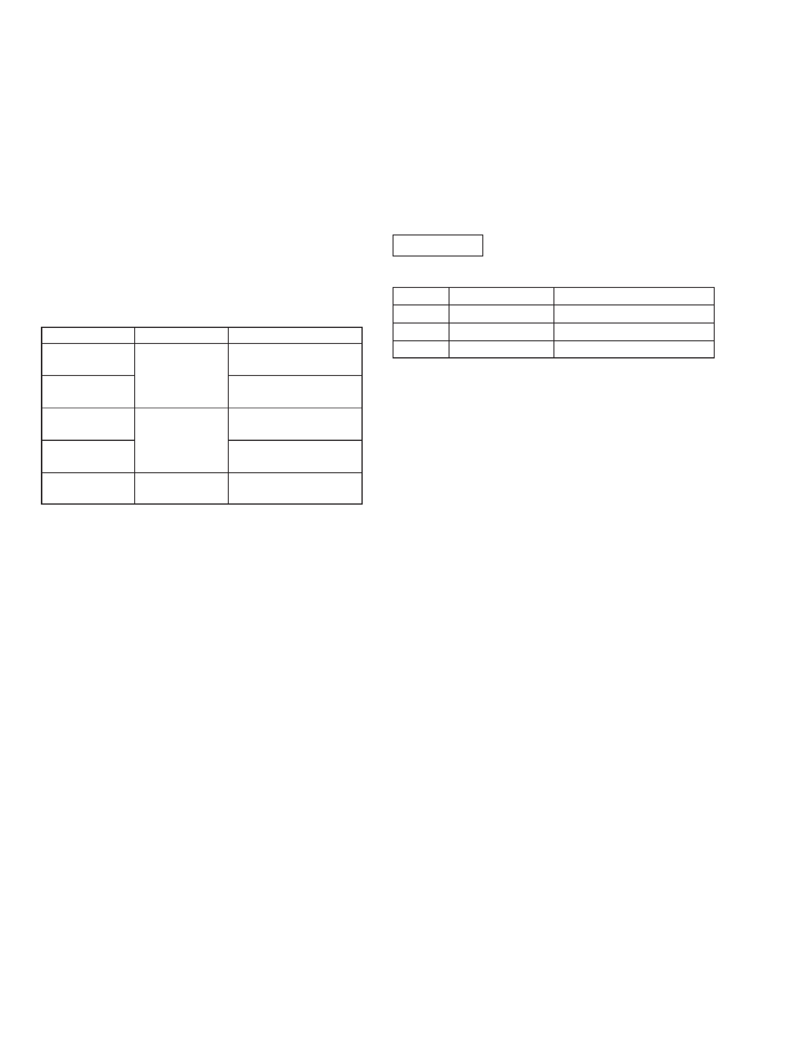
Torque Measurement
SECTION 3
MECHANICAL ADJUSTMENTS
Mode
Torque Meter
Meter Reading
CQ-102C
30-65 g·cm
FWD
(0.42-0.90 oz·inch)
FWD
1.5-6 g·cm
Back tension
(0.021-0.083 oz·inch)
CQ-102RC
30-65 g·cm
REV
(0.42-0.90 oz·inch)
REV
1.5-6 g·cm
Back tension
(0.021-0.083 oz·inch)
70-130 g·cm
FF, REW
CQ-201B
(0.98-1.80 oz·inch)
SECTION 4
ELECTRICAL ADJUSTMENTS
Note: The adjustment should be performed in the order given in
the service manual. As a rule, adjustments about playback
should be performed before those about recording.
The adjustments should be performed before for both L-CH
and R-CH.
· Switches and controls should be set as follows unless otherwise
specified.
DOLBY NR switch
: OFF
DIRECTION switch :
A
0 dB=0.775 V
Test Tape
Type
Signal
Used for
P-4-A100
10 kHz, 10 dB
Azimuth Adjustment
P-4-L300
315 Hz, 0 dB
Playback Level Adjustment
WS-48B
3 kHz, 0 dB
Tape Speed Check
Test Mode
This set will get into test mode by shorting the pins of CN801 (2P)
on MAIN board before turning the power on.
5
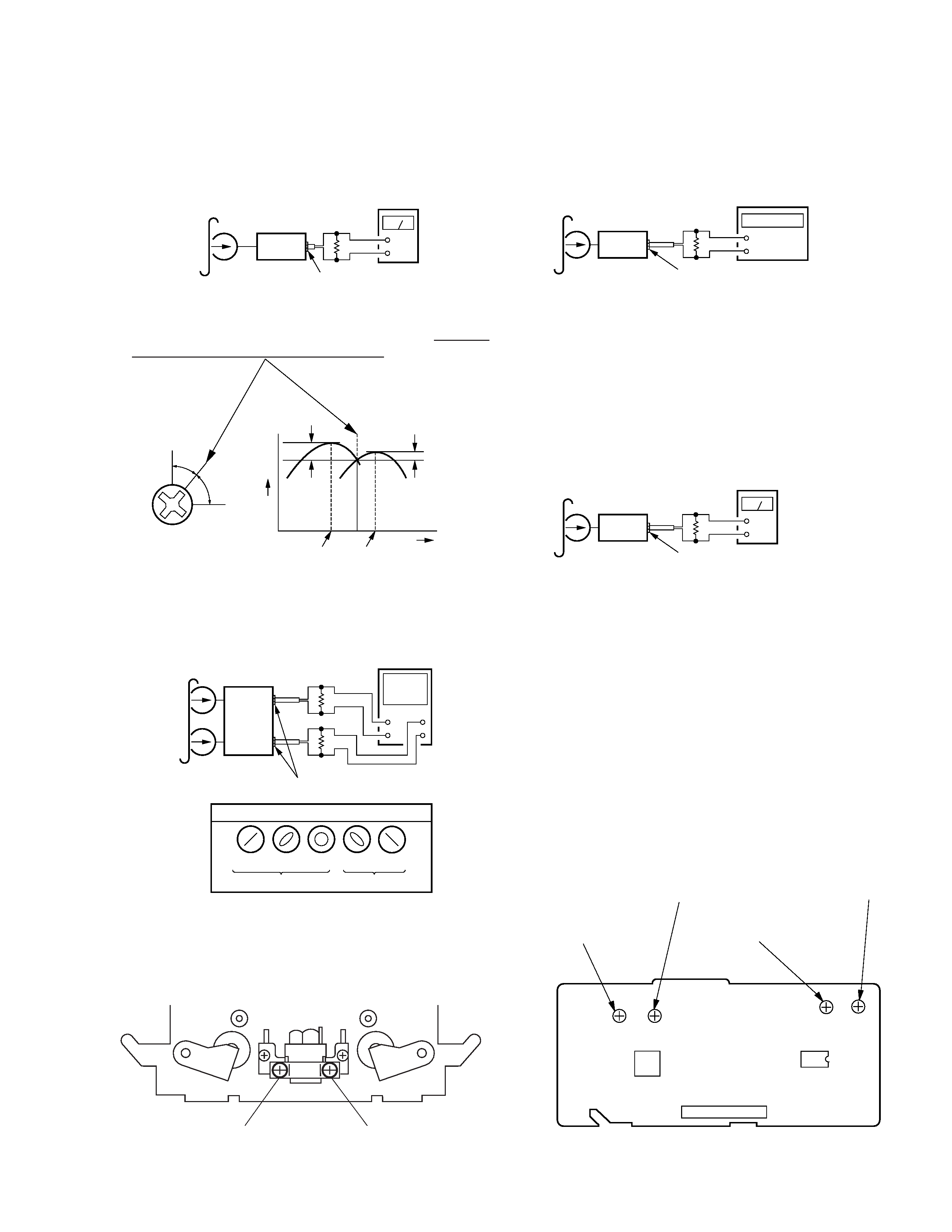
Record/Playback Head Azimuth Adjustment
Procedure:
1. Mode : REV playback
2. Turn the adjustment screw for the maximum output levels. If
these levels do not match, turn the adjustment screw until both
of output levels match together within 1 dB.
Screw
position
L-CH
peak
within
1dB
output
level
L-CH peak
R-CH peak
within
1dB
angle
R-CH
peak
3. Phase Check
Mode : playback
+
V
H
+
Screen pattern
Good
Wrong
in phase 45
° 90° 135° 180°
LINE OUT
set
R-CH
L-CH
47 k
47 k
oscilloscope
test tape
P-4-A100
(10 kHz, 10 dB)
+
set
47 k
LINE OUT
level meter
Test tape
P-4-A100
(10 kHz, 10 dB)
4. Set in the FWD mode and repeat the step 1 to 3.
5. After the adjustment, lock the screw with locking compound.
Adjustment Location: Record/Playback head
FWD side
REV side
Adjustment screw
Tape Speed Adjustment
Procedure:
Mode: FWD playback
+
set
LINE OUT
frequency counter
test tape
WS-48B
(3 kHz, 0 dB)
47 k
1. Set to FWD playback mode.
2. Adjust RV801 so that the frequency counter reading becomes
2,980 ± 30 Hz.
3. Confirm that the deviation between tape top and tape end is within
3%.
Playback Level Adjustment
Procedure:
Mode: FWD playback
Adjust RV151 (L-CH) and RV251 (R-CH) so that the reading on
level meter meets the adjustment limits below.
Adjustment Limits:
LINE OUT level: 4.7±0.5 dB (0.43 to 0.48 V)
Level difference between channels: within 2 dB
Check that the LINE OUT level does not change even if Playback
and Stop operation is repeated several times.
Adjustment Location: DECK board
Adjustment Location:
[DECK BOARD] (Component side)
+
set
LINE OUT
47 k
test tape
P-4-L300
(315 Hz, 0 dB)
level meter
IC305
CN352
T351
RV252
Record BIAS(R-CH)
RV152
Record BIAS(L-CH)
RV251
Playback Level(R-CH)
RV151
Playback Level(L-CH)