1
Model Name Using Similar Mechanism
TC-TX313
Tape Transport Mechanism Type
TC-TX101
MICROFILM
AEP Model
UK Model
E Model
Tourist Model
SERVICE MANUAL
Recording system
4-track 2-channel stereo
Frequency response (DOLBY NR OFF)
50 - 14,000 Hz (
± 3 dB),
using Sony TYPE I
cassettes
50 - 15,000 Hz (
± 3 dB),
using Sony TYPE II
cassettes
Dimensions
Approx. 142
× 125 × 235
mm (w / h / d)
incl. projecting parts and
controls
Mass
Approx. 2 kg
Design and specifications are subject to change
without notice.
· This set is the optional stereo cassette
deck that can be used only with section
HCD-101 (AEP, UK model) /
CMT-101 (E, Tourist model).
STEREO CASSETTE DECK
Dolby noise reduction manufactured under license from Dolby Labo-
ratories Licensing Corporation.
"DOLBY" and the double-D symbol a are trademarks of Dolby
Laboratories Licensing Corporation.
SPECIFICATIONS

2
TABLE OF CONTENTS
1. SERVICE NOTE
1-1. Supplying Power During Servicing ....................................... 3
2. GENERAL
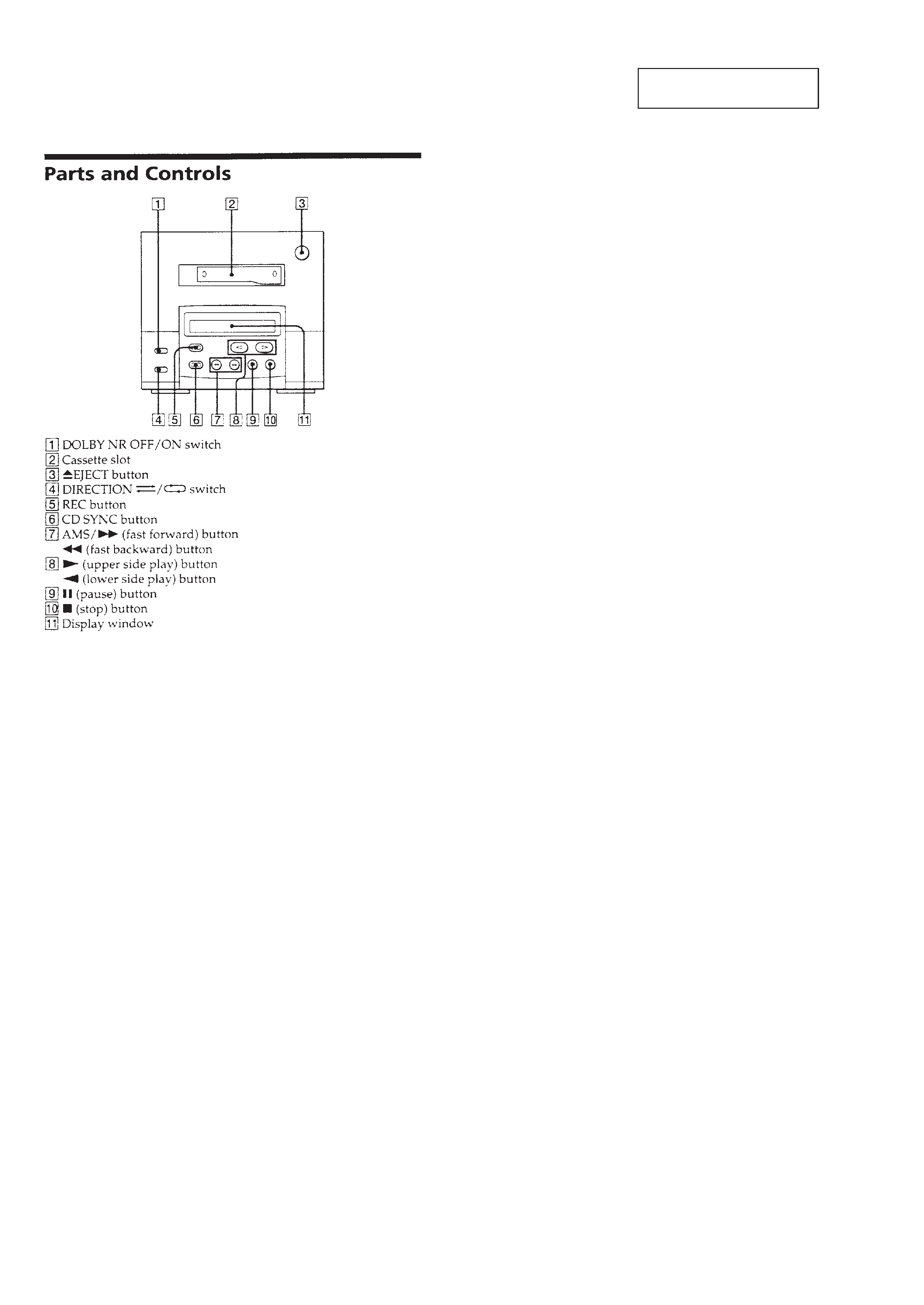
Parts and Controls ...................................................................... 4
3. TEST MODE
3-1. Checking the Items of Test Mode .......................................... 5
4. DISASSEMBLY
4-1. Top Cover .............................................................................. 6
4-2. Front Panel ............................................................................. 6
4-3. Mechanism Deck Section ...................................................... 7
4-4. PC Board Section ................................................................... 7
4-5. Main Board ............................................................................ 8
4-6. Amplifier Board ..................................................................... 8
4-7. Front Board ............................................................................ 9
4-8. Lever ...................................................................................... 9
4-9. Tension Spring ..................................................................... 10
4-10. Housing ................................................................................ 10
4-11. Chassis ................................................................................. 11
4-12. Motor (A)/(B) Assy ............................................................. 11
4-13. Head Plate ............................................................................ 12
4-14. Pinch Roller Assy ................................................................ 12
4-15. Bracket (Head Unit) ............................................................. 13
5. MECHANICAL ADJUSTMENTS ................................. 14
6. ELECTRICAL ADJUSTMENTS .................................. 14
7. DIAGRAMS
7-1. Printed Wiring Board Motor Section ............................... 17
7-2. Schematic Diagram Motor Section .................................. 18
7-3. Printed Wiring Boards Main Section ............................... 20
7-4. Schematic Diagram Main Section ................................... 23
7-5. Printed Wiring Boards Front Panel Section ..................... 27
7-6. Schematic Diagram Front Panel Section ......................... 29
7-7. IC Pin Description ............................................................... 31
8. EXPLODED VIEWS
8-1. Chassis Section .................................................................... 33
8-2. PC Board Section ................................................................. 34
8-3. TCM Assy Section ............................................................... 35
9. ELECTRICAL PARTS LIST .......................................... 36
SAFETY-RELATED COMPONENT WARNING!!
COMPONENTS IDENTIFIED BY MARK ! OR DOTTED LINE
WITH MARK ! ON THE SCHEMATIC DIAGRAMS AND IN
THE PARTS LIST ARE CRITICAL TO SAFE OPERATION.
REPLACE THESE COMPONENTS WITH SONY PARTS WHOSE
PART NUMBERS APPEAR AS SHOWN IN THIS MANUAL OR
IN SUPPLEMENTS PUBLISHED BY SONY.
Notes on Chip Component Replacement
· Never reuse a disconnected chip component.
· Notice that the minus side of a tantalum capacitor may be dam-
aged by heat.
3
P707, 909
PFJ-1
(Power Supply jig)
POWER SW
Connector Cable 17P
(supplied with set)
set
Conversion Board
(J-2501-144-A)
SYSTEM CONTROL
Power Function
SECTION 1
SERVICE NOTE
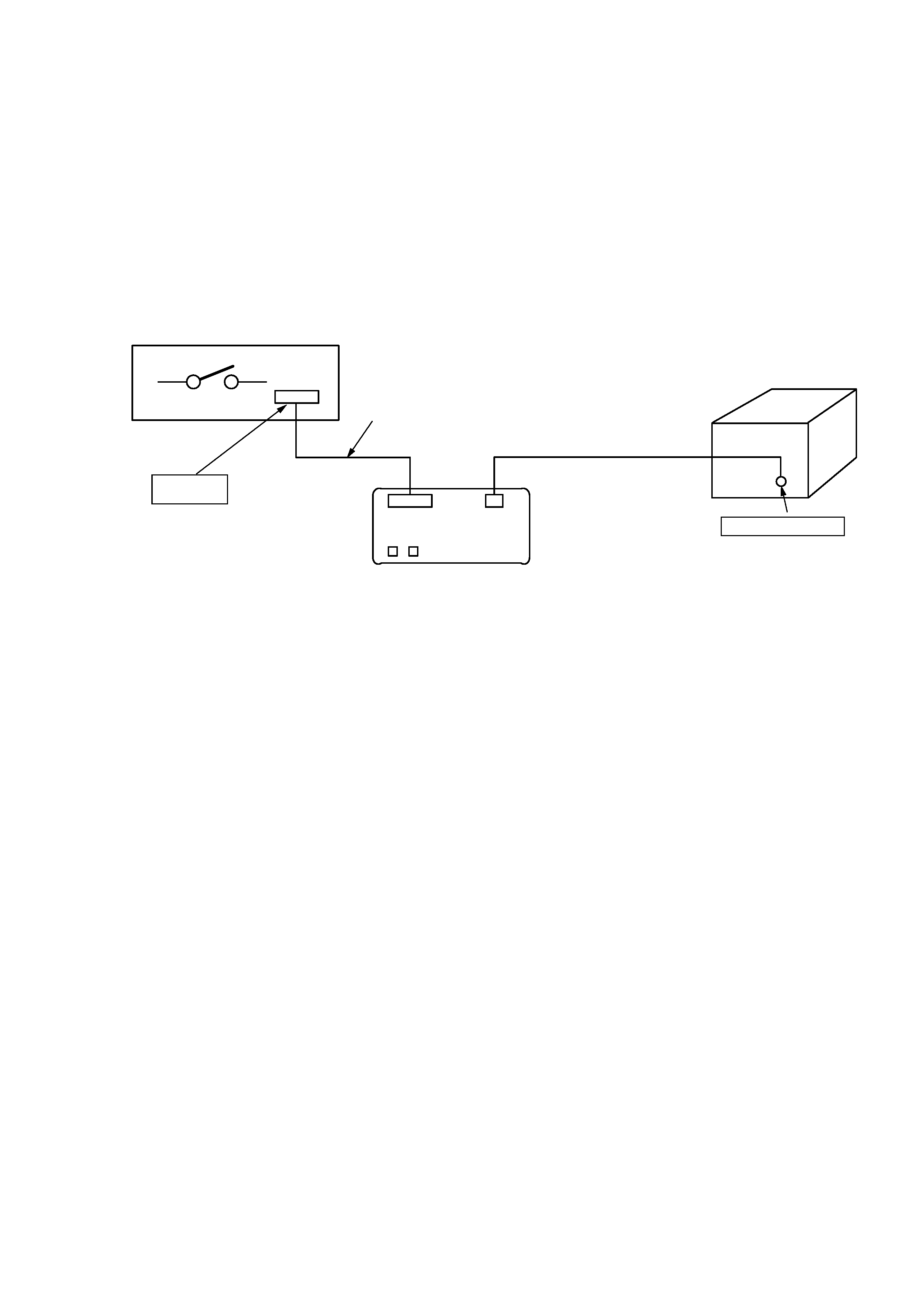
1-1. SUPPLYING POWER DURING SERVICING
This equipment cannot operate without using a separate power
supply. Connect this set to the HCD-101.
To apply power set the SYSTEM POWER switch of HCD-101.
When other units are not available use the PFJ-1 power supply jig.
When using the PFJ-1, press the POWER switch of the conversion
board to turn on the power.
· Connection Diagram
* When checking the recording
function of TC-TX101, select
any function other than TAPE
using the Function key of
the conversion board before
check.
4
SECTION 2
GENERAL
This section extracted from
instruction manual.

5
SECTION 3
TEST MODE
3-1. CHECKING THE ITEMS OF TEST MODE
The set allows you to check the items of the test mode although this
may not be directly related with the adjustment.
1 Setting/Releasing the Test Mode:
1) Setting
With power OFF, short between test pin
1 and pin 2 of
TP1 on the MAIN board. (See page 16.)
Then, turn power ON to enter the test mode.
2) Releasing
Open between pin
1 and pin 2 of TP1.
2 Items of Test Mode
1) Memory Stop
1-1) In side A record mode, press the REW ( 0 ) button.
The tape is rewind to the start point of recording and stopped.
1-2) In side B record mode, press the FF ( ) ) button.
The tape is rewind to the start point of recording and stopped.
2) Memory Play
2-1) In side A record mode, press the FWD Auto Play
( " + 0 ) buttons simultaneously. The tape is rewind to
the start point of recording and FWD played.
2-2) In side B record mode, press the REV Auto Play
( " + ) ) buttons simultaneously. The tape is rewind to
the start point of recording and REV played.
3) All LED Flickering
When no tape is inserted, all LED indicators are flickering.
4) Aging Operation
When tape with record erase preventing claw is inserted for
both sides A and B, enter the aging operation start command
by pressing p and CD SYNC simultaneously. The system
will change the direction to one side and perform the
following operations:
1 Rewind in REW mode until side A of tape is stopped.
2 Playback tape in FWD mode for 1 minute.
3 Pause mode.
4 Record tape for 3 minutes.
5 Forward tape in FF mode to the end of side A of tape.
6 Shut off and switch to side B.
7 Playback tape in REV mode for 1 minute.
8 Pause mode.
9 Record tape for 3 minutes.
!º Forward tape in FF mode to the end of side B of tape.
!¡ Shut off and switch to side A.
!TM Repeat the procedure from 2 to !¡.
!£ Pressing the STOP ( p ) button will release the set from
these operations.