SERVICE MANUAL
STEREO CASSETTE DECK
AEP Model
UK Model
E Model
Australian Model
SPECIFICATIONS
TC-S9
Ver 1.0 2001.09
9-873-281-01
Sony Corporation
2001I0500-1
Home Audio Company
C
2001.9
Shinagawa Tec Service Manual Production Group
TC-S9 is the Tape deck section
in MHC-S9D.
Tape deck
Model Name Using Similar Mechanism
TC-S3
Section
Tape Transport Mechanism Type
TCM-230AWR41,
TCM-230MWR41
Dolby noise reduction manufactured under license
from Dolby Laboratories Licensing Corporation.
"DOLBY" and the double-D symbol ; are trade-
marks of Dolby Laboratories Licensing Corporation.
Recording system
4-track 2-channel stereo
Frequency response
60 13,000 Hz (
±3 dB),
(DOLBY NR OFF)
using Sony TYPE I
cassette,
60 14,000 Hz (
±3 dB),
using Sony TYPE II
cassette
Dimensions (w/h/d)
Approx. 280 x 128 x 330 mm
Mass
Approx. 2.4 kg
Design and specifications are subject to change
without notice.

2
TC-S9
TABLE OF CONTENTS
1.
SERVICING NOTES ................................................ 3
2.
GENERAL
Location of Controls .......................................................
4
3.
DISASSEMBLY
3-1. Disassembly Flow ...........................................................
5
3-2. Case .................................................................................
5
3-3. MAIN Board ...................................................................
6
3-4. Front Panel Section .........................................................
6
3-5. Tape Mechanism Deck
(TCM-230AWR41, TCM-230MWR41) .........................
7
3-6. LEAF SW Board, HEAD (A) Board and
HEAD (B) Board ............................................................
7
4.
TEST MODE .............................................................. 8
5.
MECHANICAL ADJUSTMENTS ....................... 9
6.
ELECTRICAL ADJUSTMENTS ......................... 9
7.
DIAGRAMS
7-1. Note for Printed Wiring Boards and
Schematic Diagrams ....................................................... 13
7-2. Schematic Diagram MAIN Section (1/2) ................ 14
7-3. Schematic Diagram MAIN Section (2/2) ................ 15
7-4. Printed Wirings Boards MAIN Section ................... 16
7-5. Schematic Diagram LEAF SW Section ................. 17
7-6. Printed Wiring Board LEAF SW Section ............... 17
7-7. Schematic Diagram PANEL Section ....................... 18
7-8. Printed Wiring Boards PANEL Section .................. 18
7-9. IC Pin Function Description ........................................... 19
8.
EXPLODED VIEWS
8-1. General Section ............................................................... 21
8-2. Front Panel Section ......................................................... 22
8-3. Tape Mechanism Deck Section
(TCM-230AWR41) .......................................................... 23
8-4. Tape Mechanism Deck Section
(TCM-230MWR41) ........................................................ 24
8-5. Sub Chassis Assy Section
(TCM-230MWR41) ........................................................ 25
9.
ELECTRICAL PARTS LIST ............................... 26
Notes on chip component replacement
· Never reuse a disconnected chip component.
· Notice that the minus side of a tantalum capacitor may be dam-
aged by heat.
SAFETY-RELATED COMPONENT WARNING!!
COMPONENTS IDENTIFIED BY MARK 0 OR DOTTED
LINE WITH MARK 0 ON THE SCHEMATIC DIAGRAMS
AND IN THE PARTS LIST ARE CRITICAL TO SAFE
OPERATION. REPLACE THESE COMPONENTS WITH
SONY PARTS WHOSE PART NUMBERS APPEAR AS
SHOWN IN THIS MANUAL OR IN SUPPLEMENTS PUB-
LISHED BY SONY.
3
TC-S9
SECTION 1
SERVICING NOTES
Model
PART No.
AEP and UK models
4-236-839-0[]
Australian, Saudi Arabia
and Korean models
4-236-839-1[]
E and Singapore models
4-236-839-2[]
Mexican model
4-236-839-3[]
Thai model
4-236-839-4[]
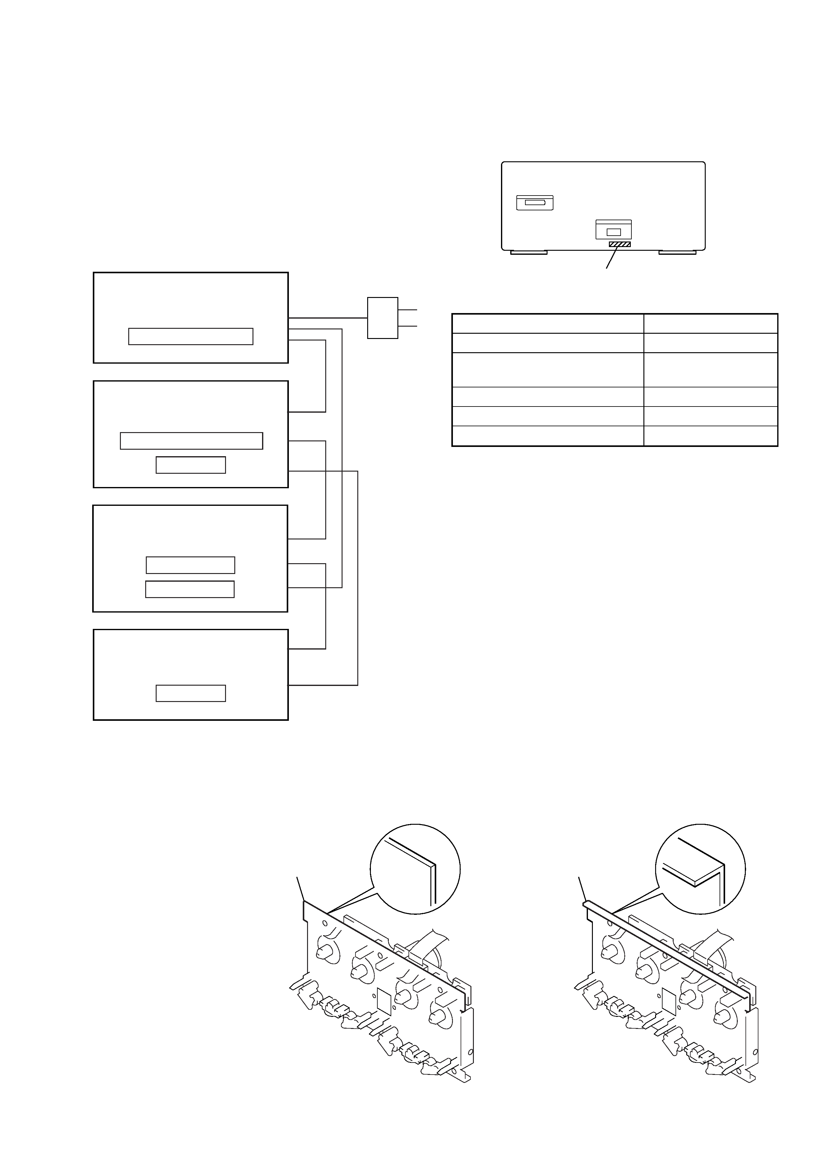
· MODEL IDENTIFICATION
Rear Panel
This set is a component of the MHC-S9D.
The MHC-S9D system configuration is as shown below, and there-
fore it does not operate normally unless all four components are
connected.
In performing the repair, connect all components with the system
cables.
Note: The precaution to the users is described on the label stuck
on the back panel (DVD/video CD/CD player) and in the trouble-
shooting section in the Operation Manual.
System Configuration:
POWER SUPPLY
AC IN
TA
MASTER & GRAPHIC
µcon
ST
TC
µcon
TC
DISPLAY
HTC & MB
µcon
DVP
POWER BLOCK
PART No.
· TAPE MECHANISM DECK DISCRIMINATION
TCM-230AWR41 and TCM-230MWR41 are used for the tape
mechanism deck of this set, and they can be discriminated as shown
below.
main chassis
straight
L-shape
TCM-230AWR41
TCM-230MWR41
main chassis
4
TC-S9
SECTION 2
GENERAL
This section is extracted from
instruction manual.
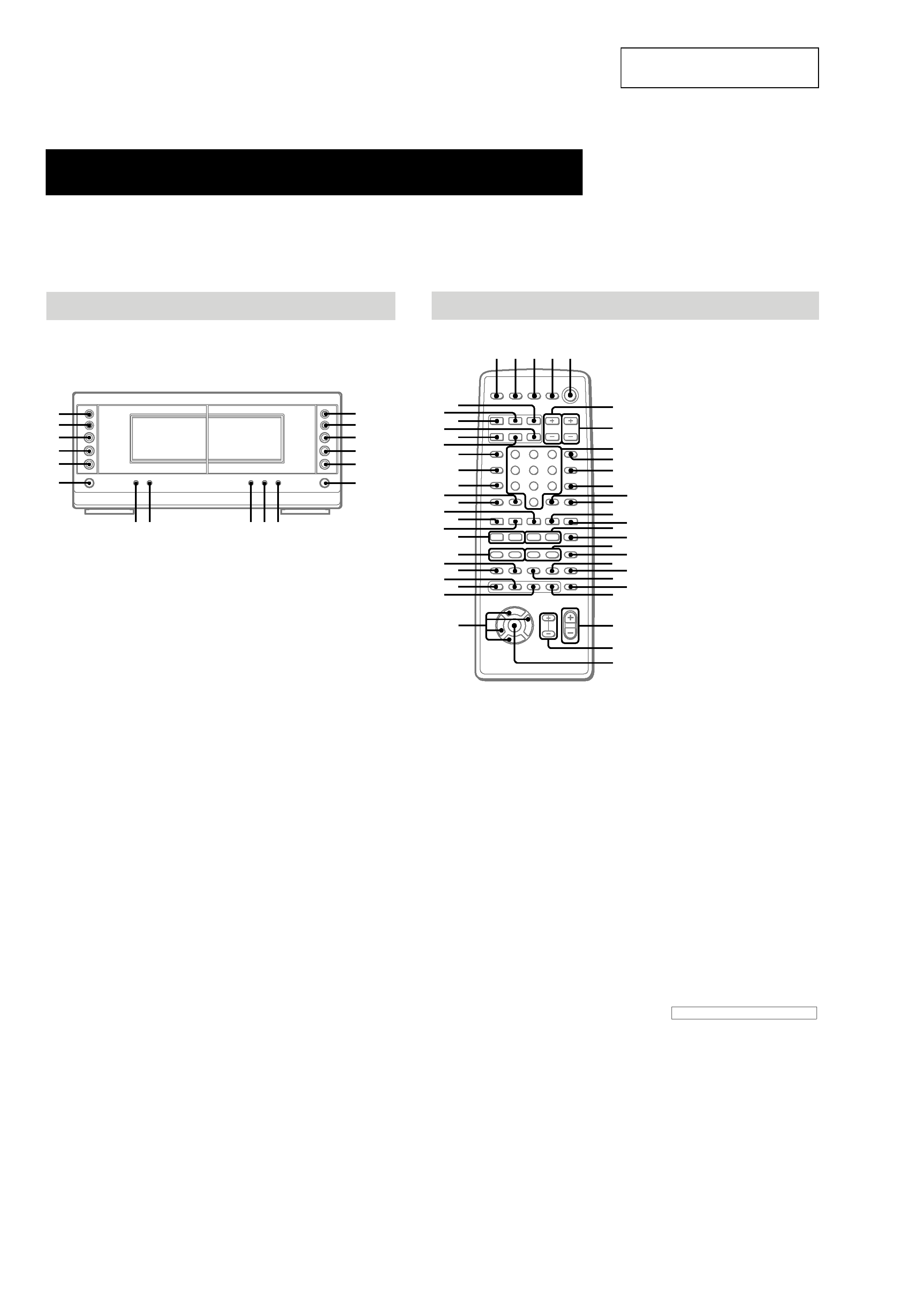
LOCATION OF CONTROLS
Cassette deck
CD SYNC ta (45, 46)
DIRECTION tf (44, 45, 46, 55)
DOLBY NR td (4446)
HI-DUB ts (45)
REC PAUSE/START t; (45, 46, 55)
Deck A
N
(forward play) tk (44, 55, 63)
n
(reverse play) tj (44, 63)
x
(stop) th (44)
>/M
(go forward/fast
forward) y; (44)
./m
(go back/rewind) tl
(44)
Z
(eject) tg (44, 63)
Deck B
N
(forward play) rh (44, 45, 63)
n
(reverse play) rj (44, 45, 63)
x
(stop) rk (44, 45, 55)
M/>
(fast forward/go
forward) rf (44)
m/.
(rewind/go back) rg
(44)
Z
(eject) rl (44, 63)
hH
AUTO REVERSE
hH
AUTO REVERSE
M
>
m
H
.
h
x
M
>
m
H
.
h
x
A
A
y;
tl
tk
tj
th
tg
rf
rg
rh
rj
rk
rl
t;
ta
ts
td
tf
Main unit
Parts Identification
The items are arranged in alphabetical order.
Refer to the pages indicated in parentheses ( ) for details.
Remote control
ANGLE es (37)
AUDIO ws (34)
CLEAR qs (22, 29, 30, 36)
CLOCK/TIMER SELECT 3
(47, 56)
CLOCK/TIMER SET 2 (17, 47,
56)
DBFB ra (48)
D.SKIP 9 (26)
DIGITAL rf (57)
DISPLAY rj (17, 31, 32, 43, 54)
DVD DISPLAY wd (18, 19, 30,
3234, 3640)
DVD MENU wa (27)
DVD SET UP ql (18, 19, 24, 39)
ENTER wj
EQ ea (52)
EQ ON/OFF wl (53)
FILE SELECT +/ wh (48, 49,
53)
FUNCTION rd (18, 25, 27, 28,
36, 45, 46, 55, 57)
GROOVE rs (48)
KARAOKE PON (Except for
European model) el (54)
MD rh (57)
Numeric buttons 8 (28, 30)
PLAY MODE qa (25, 28, 29, 46)
REPEAT q; (30)
RETURN O qd (27, 39, 40)
SELECT DVD N eh (20, 25,
27, 29, 30)
SET UP wf (14, 16, 51, 53, 54)
SLEEP 1 (55)
SLOW t/T qk (26)
SPECTRUM ANALYZER rk
(54)
STEP c/C ef (26)
SUBTITLE ed (37)
SUR e; (51)
TAPE A nN ek (44)
TAPE B nN qf (44, 45)
TITLE w; (27)
TUNER/BAND ej (42)
TV @/1 4 (13)
TV CH +/ 7 (13)
TV/VIDEO rl (13)
TV VOL +/ 6 (13)
VIDEO rg (57)
VOL +/ wg
x
M
m
>
.
nN
O
X
T
t
C
c
V
v
Bb
12
3
4 5
e;
es
ef
ej
eg
6
7
9
8
q;
qa
qd
qs
qf
qg
qj
qh
qk
ql
wa
wd
ws
wf
w;
wg
wj
wh
wk
ed
wl
ea
eh
el
rs
ra
rd
ek
r;
rg
rj
rl
rf
rh
rk
BUTTON DESCRIPTIONS
@/1
(power) 5
X
(pause) qj
x
(stop) qg
m/M
(rewind/fast forward),
TUNING /+ qh
./>
(go back/go forward),
PRESET /+, PREV/NEXT eg
O/o/P/p wk
>10 r;
TC-S9
5
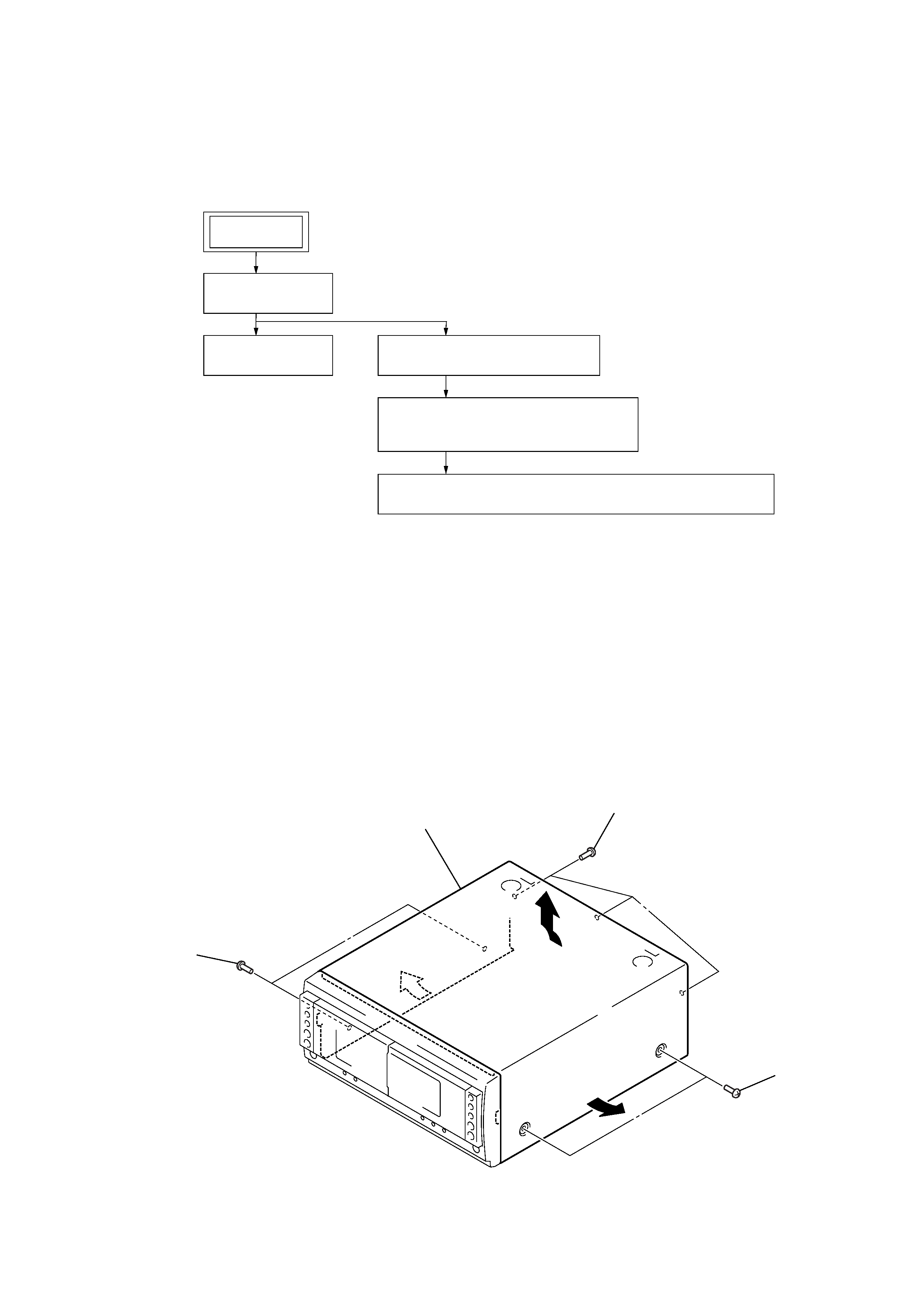
· This set can be disassembled in the order shown below.
3-1.
DISASSEMBLY FLOW
SECTION 3
DISASSEMBLY
Note: Follow the disassembly procedure in the numerical order given.
3-2.
CASE
3-2. CASE
(Page 5)
3-3. MAIN BOARD
(Page 6)
3-4. FRONT PANEL SECTION
(Page 6)
3-6. LEAF SW BOARD, HEAD (A) BOARD AND HEAD (B) BOARD
(Page 7)
3-5. TAPE MECHANISM DECK
(TCM-230AWR41, TCM-230MWR41)
(Page 7)
SET
2
two screws
(case 3 TP2)
3
3
2
two screws
(case 3 TP2)
1
three screws
(BVTT3
× 6)
4
Remove the case in the
direction of arrow A.
A