SERVICE MANUAL
STEREO CASSETTE DECK
AEP Model
UK Model
E Model
Australian Model
SPECIFICATIONS
TC-S3
Ver 1.0 2001.04
9-873-837-11
Sony Corporation
2001D0500-1
Home Audio Company
C
2001.4
Shinagawa Tec Service Manual Production Group
TC-S3 is the Tape deck section
in MHC-S7AV/SV7AV/S3.
Recording system
4-track 2-channel stereo
Frequency response
60 13,000 Hz (
±3 dB),
(DOLBY NR OFF)
using Sony TYPE I
cassette,
60 14,000 Hz (
±3 dB),
using Sony TYPE II
cassette
Wow and flutter
±0.15% W.Peak (IEC)
0.1% W.RMS (NAB)
±0.2% W.Peak (DIN)
Dimensions (w/h/d)
Approx. 280 x 128 x 330 mm
Mass
Approx. 2.4 kg
Design and specifications are subject to change
without notice.
Tape deck
Model Name Using Similar Mechanism
NEW
Section
Tape Transport Mechanism Type
TCM-230AWR41/
230MWR41
Dolby noise reduction manufactured under license
from Dolby Laboratories Licensing Corporation.
"DOLBY" and the double-D symbol ; are trade-
marks of Dolby Laboratories Licensing Corporation.

2
TC-S3
TABLE OF CONTENTS
1.
SERVICING NOTES ................................................ 3
2.
GENERAL
Location of Controls .......................................................
4
3.
DISASSEMBLY
3-1. Disassembly Flow ...........................................................
6
3-2. Cover ...............................................................................
6
3-3. MAIN Board ...................................................................
7
3-4. Front Panel Section .........................................................
7
3-5. Tape Mechanism Deck
(TCM-230AWR41/230MWR41) ....................................
8
3-6. LEAF SW Board, HEAD (A) Board,
HEAD (B) Board ............................................................
8
4.
TEST MODE .............................................................. 9
5.
MECHANICAL ADJUSTMENTS ....................... 10
6.
ELECTRICAL ADJUSTMENTS ......................... 10
7.
DIAGRAMS
7-1. Note for Printed Wiring Boards and
Schematic Diagrams ....................................................... 13
7-2. Schematic Diagram MAIN Section (1/2) ................ 14
7-3. Schematic Diagram MAIN Section (2/2) ................ 15
7-4. Printed Wiring Board MAIN Section ...................... 16
7-5. Schematic Diagram LEAF SW Section ................. 17
7-6. Printed Wiring Board LEAF SW Section ............... 17
7-7. Schematic Diagram PANEL Section ....................... 18
7-8. Printed Wiring Boards PANEL Section .................. 18
7-9. IC Pin Function Description ........................................... 19
8.
EXPLODED VIEWS
8-1. General Section ............................................................... 21
8-2. Front Panel Section ......................................................... 22
8-3. Tape Mechanism Deck Section-1
(TCM-230AWR41/230MWR41) .................................... 23
8-4. Tape Mechanism Deck Section-2
(TCM-230AWR41/230MWR41) .................................... 24
9.
ELECTRICAL PARTS LIST ............................... 25
Notes on chip component replacement
· Never reuse a disconnected chip component.
· Notice that the minus side of a tantalum capacitor may be dam-
aged by heat.
SAFETY-RELATED COMPONENT WARNING!!
COMPONENTS IDENTIFIED BY MARK 0 OR DOTTED
LINE WITH MARK 0 ON THE SCHEMATIC DIAGRAMS
AND IN THE PARTS LIST ARE CRITICAL TO SAFE
OPERATION. REPLACE THESE COMPONENTS WITH
SONY PARTS WHOSE PART NUMBERS APPEAR AS
SHOWN IN THIS MANUAL OR IN SUPPLEMENTS PUB-
LISHED BY SONY.
3
TC-S3
SECTION 1
SERVICING NOTES
This set is a component of the MHC-S7AV, MHC-SV7AV and
MHC-S3.
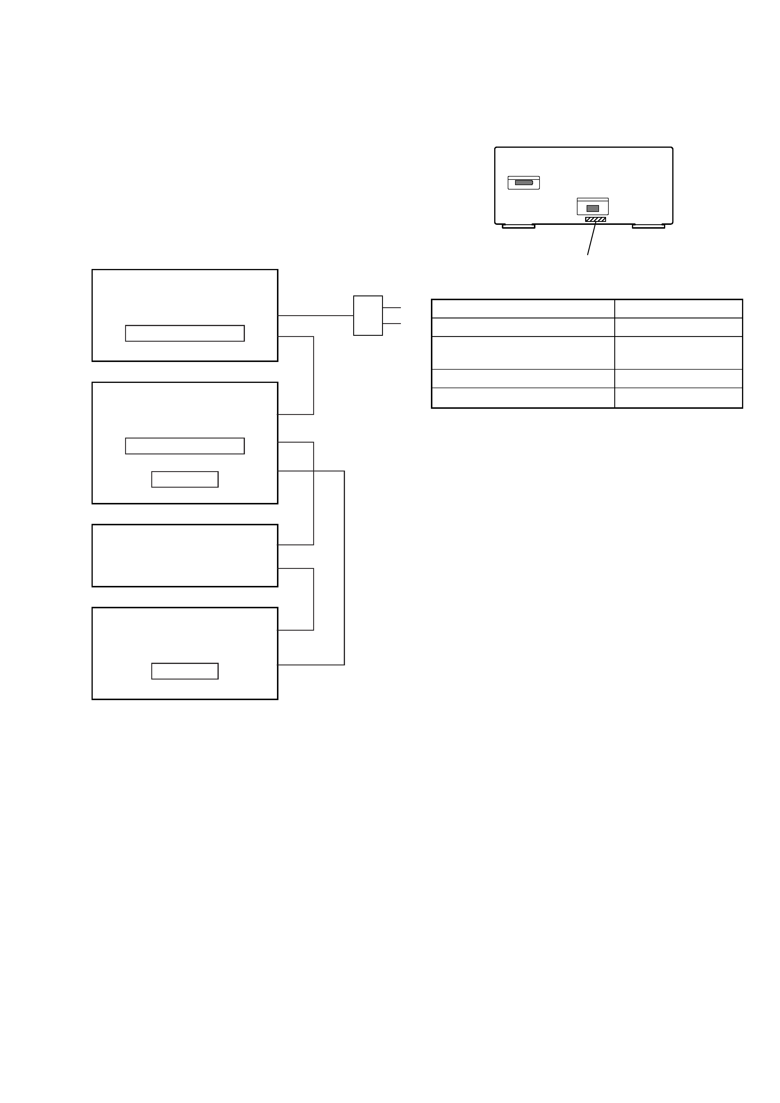
The MHC-S7AV/SV7AV/S3 system configuration is as shown be-
low, and therefore it does not operate normally unless all four com-
ponents are connected.
In performing the repair, connect all components with the system
cables.
Note: The precaution to the users is described on the label stuck on
the back panel (CD player) and in the troubleshooting section in
the Operation Manual.
System Configuration:
POWER SUPPLY
AC IN
TA
SYSTEM & CD
µcon
ST
CDP
TC
µcon
TC
DISPLAY
Model
PART No.
AEP and UK models
4-233-093-0[]
Australian, Saudi Arabia
and Korean models
4-233-093-1[]
Sigapore model
4-233-093-2[]
Thailand and Mexican models
4-233-093-3[]
· MODEL IDENTIFICATION
Rear Panel
PART No.
4
TC-S3
SECTION 2
GENERAL
This section is extracted from
instruction manual.
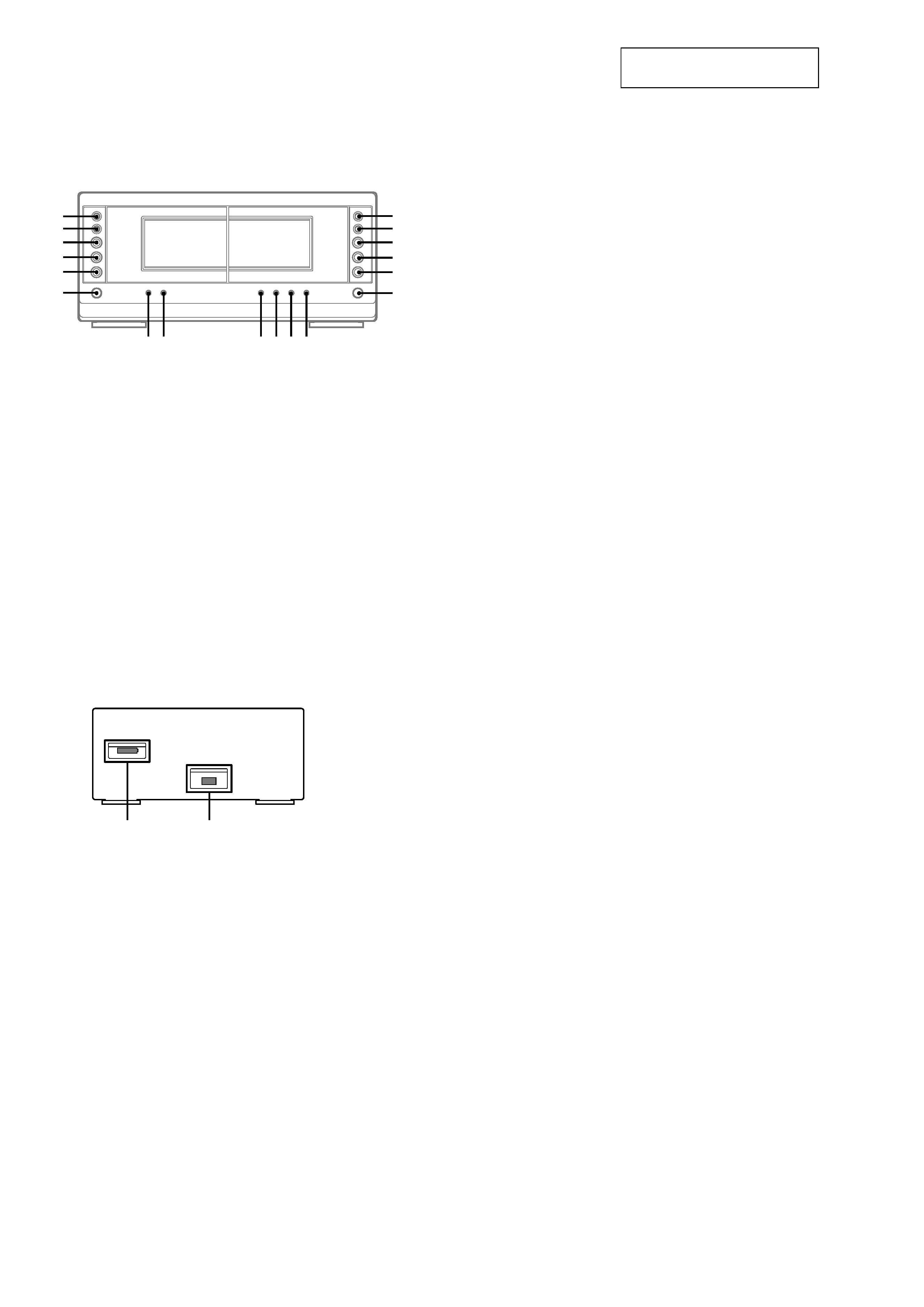
LOCATION OF CONTROLS
Front Panel
2
1
Rear Panel
hH
AUTO REVERSE
hH
AUTO REVERSE
M
>
m
H
.
h
x
M
>
m
H
.
h
x
A
A
th
tg
tf
td
ts
ta
el
r;
ra
rs
rd
rf
rg
rh
rj
rk
rl
t;
CD SYNC rh (20, 21)
DIRECTION t; (19, 20, 21)
DOLBY NR rl (19, 20)
EDIT rk (21)
HI-DUB rj (20)
REC PAUSE/START rg (20, 21)
Deck A
N (forward play) tf (19, 35)
n (reverse play) td (19, 35)
x (stop) ts (19)
M/> (fast forward/go
forward) th (19)
m/. (rewind/go back) tg
(19)
Z (eject) ta (19)
Deck B
N (forward play) ra (19, 20, 35)
n (reverse play) rs (19, 20, 35)
x (stop) rd (19, 20)
M/> (fast forward/go
forward) el (19)
m/. (rewind/go back) r;
(19)
Z (eject) rf (19)
1 SYSTEM CONTROL 5 connector
(FROM CDP-S3/MCE-VS77)
2 SYSTEM CONTROL 4 connector
(FROM ST-S5/S3/VS77)
5
TC-S3
6
x
hH
H
hH
O
o
Pp
M
m
X
>
.
12 3
wg
qh
qa
wk
wj
wh
wa
4
5
6
7
qs
qf
qd
qg
8
9
q;
qk
ql
w;
qj
wd
ws
wf
es
ea
e;
wl
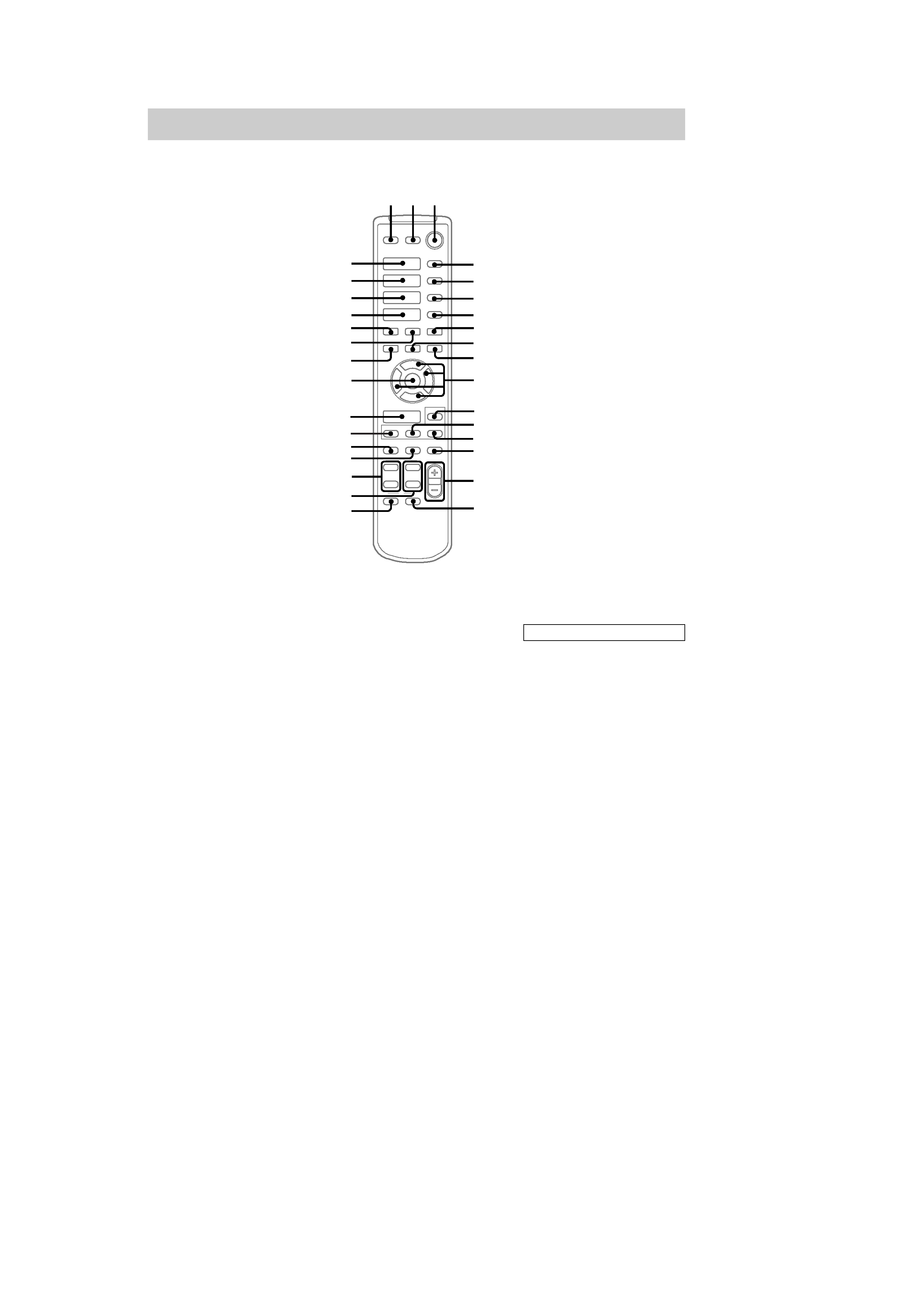
Remote Control
CD H es (14, 15)
CHECK 5 (15)
CLEAR 6 (15)
CLOCK/TIMER SELECT qj
(30)
CLOCK/TIMER SET qk (13, 21,
29)
DBFB qg (23)
DISPLAY ws (13, 16, 18, 29, 35)
D.SKIP 4 (14)
ENTER wg (10, 12, 13, 15, 17,
18, 21, 22, 2630)
EQ qd (27)
EQ ON/OFF qf (10, 28)
FUNCTION wf (10, 14, 15, 20,
21, 31)
GROOVE wa (23)
SET UP qs (10, 12, 26, 28, 29)
SLEEP 7 (29)
SUR wd (25)
TAPE A hH ea (19, 35)
TAPE B hH e; (19, 20, 35)
TUNER/BAND wl (17)
TUNING + 9 (17)
TUNING wh (17)
TV CH +/ ql
TV VOL +/ w;
TV @/1 2
TV/VIDEO 1
VOL +/ qh
BUTTON DESCRIPTIONS
@/1 (power) 3
X (pause) q;
x (stop) 8
. (go back) wk
> (go forward) wj
m (rewind) wh
M (fast forward) 9
O/o/P/p qa