
SERVICE MANUAL
STEREO CASSETTE DECK
AEP Model
TC-KE240/RE340
UK Model
TC-KE240
E Model
Australian Model
TC-RE340
SPECIFICATIONS
TC-KE240/RE340
Photo: TC-RE340 (Black type)
Dolby noise reduction and HX Pro headroom ex-
tension manufactured under license from Dolby
Laboratories Licensing Corporation.
HX Pro originated by Bang & Olufsen.
"DOLBY", the double-D symbol ;, and "HX PRO"
are trademarks of Dolby Laboratories Licensing Cor-
poration.
Model Name Using Similar Mechanism
NEW
Tape Transport Mechanism Type
KE240
TCM-230ASV1
RE340
TCM-230ASR4N
Continued on next page
System
Recording system
4-track 2-channel stereo
Fast-winding time (approx.)
100 sec. (with Sony C-60 cassette)
Bias
AC bias
Signal-to-noise ratio (at peak level and weighted with Dolby
NR off)
Type I tape, Sony Type I (NORMAL): 55 dB
Type II tape, Sony Type II (HIGH): 57 dB
Type IV tape, Sony Type IV (METAL): 58 dB
S/N ratio improvement (approximate values)
With Dolby B NR on: 5 dB at 1 kHz, 10 dB at 5 kHz
With Dolby C NR on: 15 dB at 500 Hz, 20 dB at 1 kHz
Harmonic distortion
0.4% (with Type I tape, Sony Type I (NORMAL):
160 nWb/m 315 Hz, 3rd H.D.)
1.8% (with Type IV tape, Sony Type IV (METAL):
250 nWb/m 315 Hz, 3rd H.D.)
Type I tape, Sony Type I
(NORMAL)
30 15,000 Hz (±3 dB, IEC),
20 16,000 Hz (±6 dB)
Type II tape, Sony Type II
(HIGH)
30 16,000 Hz (±3 dB, IEC),
20 17,000 Hz (±6 dB)
Type IV tape, Sony Type IV
(METAL)
30 18,000 Hz (±3 dB, IEC),
20 19,000 Hz (±6 dB),
30 13,000 Hz (±3 dB, 4 dB
recording)
Frequency response (Dolby NR off)
Tape type
Inputs
Line inputs (phono jacks)
Sensitivity: 0.16 V
Input impedance: 47 kilohms

2
SAFETY-RELATED COMPONENT WARNING!!
COMPONENTS IDENTIFIED BY MARK 0 OR DOTTED
LINE WITH MARK 0 ON THE SCHEMATIC DIAGRAMS
AND IN THE PARTS LIST ARE CRITICAL TO SAFE
OPERATION. REPLACE THESE COMPONENTS WITH
SONY PARTS WHOSE PART NUMBERS APPEAR AS
SHOWN IN THIS MANUAL OR IN SUPPLEMENTS PUB-
LISHED BY SONY.
Notes on chip component replacement
· Never reuse a disconnected chip component.
· Notice that the minus side of a tantalum capacitor may be dam-
aged by heat.
Outputs
Line outputs (phono jacks)
Rated output level: 0.5 V at a load impedance of
47 kilohms
Load impedance: Over 10 kilohms
Headphones (stereo phone jack)
Output level: 0.25 mW at a load impedance of
32 ohms
General
Power requirements
Europe and certain countries in Asia: 220 230 V AC, 50/
60 Hz
Australia: 240 V AC, 50/60 Hz
Other countries: 110 120/220 240 V AC, 50/60 Hz
Power consumption
TC-RE340: 15 W
TC-KE240: 14 W
Dimensions (approx.) (w/h/d)
430
× 120 × 290 mm
Mass (approx.)
3.3 kg
Supplied accessories
Audio connecting cords (2)
Design and specifications are subject to change without notice.
3
SECTION 1
SERVICING NOTE
TABLE OF CONTENTS
1.
SERVICING NOTE .................................................. 3
2.
GENERAL ................................................................... 4
3.
DISASSEMBLY ......................................................... 5
4.
MECHANICAL ADJUSTMENTS ....................... 10
5.
SERVICE MODE ...................................................... 11
6.
ELECTRICAL ADJUSTMENTS ......................... 12
7.
DIAGRAMS
7-1. Note for Printed Wiring Boards and
Schematic Diagrams ....................................................... 15
7-2. Printed Wiring Boards HEAD RELAY (REC/PB)/
LEAF SW (REC/PB) Boards ....................................... 18
7-3. Printed Wiring Board MAIN Board ........................ 19
7-4. Schematic Diagram MAIN Section (1/2) ................ 20
7-5. Schematic Diagram MAIN Section (2/2) ................ 21
7-6. Printed Wiring Boards
TRANS/POWER SW Boards ................................... 22
7-7. Schematic Diagram
TRANS/POWER SW Boards ................................... 23
7-8. Printed Wiring Board DISPLAY Board .................. 24
7-9. Schematic Diagram DISPLAY Board ..................... 25
7-10. Printed Wiring Boards KEY/HP Boards ................. 26
7-11. Schematic Diagram KEY Board ............................. 26
7-12. IC Pin Function Description ........................................... 28
8.
EXPLODED VIEWS ................................................ 30
9.
ELECTRICAL PARTS LIST ............................... 33
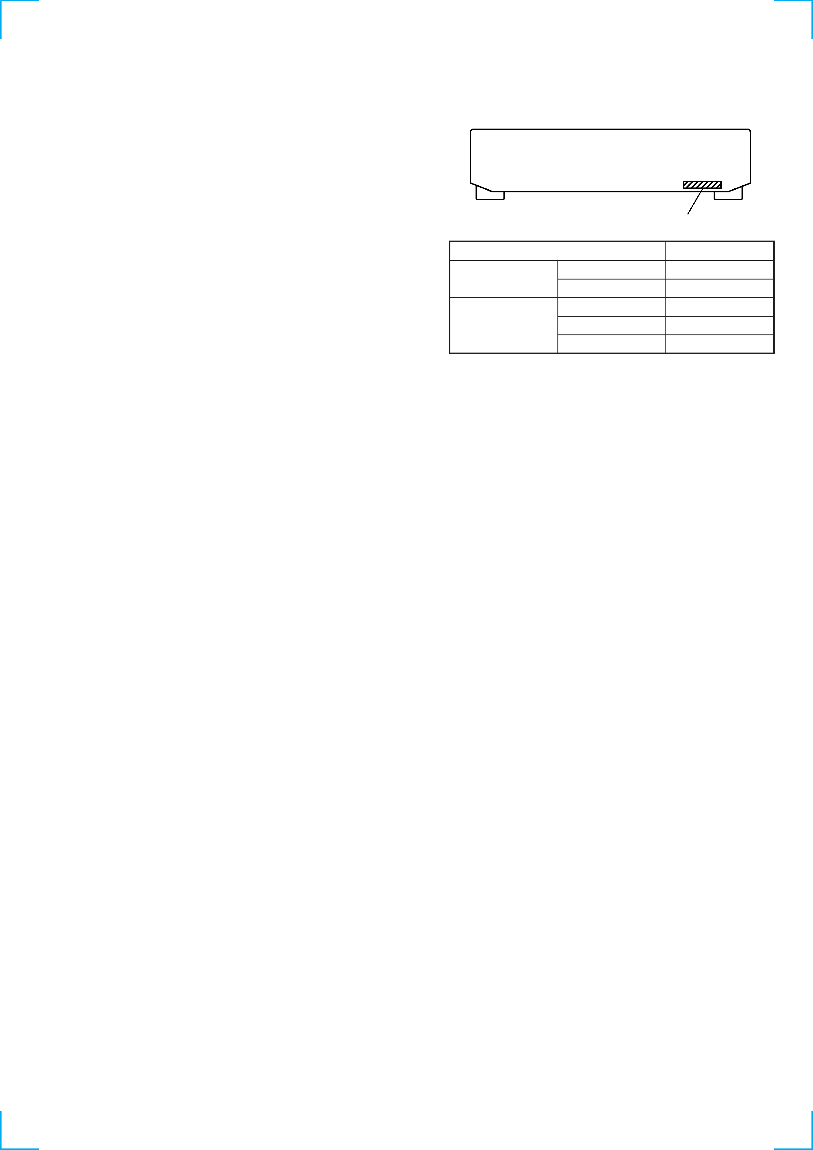
MODEL IDENTIFICATION
BACK PANEL
Part No.
Model
Part No.
TC-KE240
AEP model
3-042-502-0s
UK model
3-042-502-1s
AEP model
3-042-490-0s
TC-RE340
Australian model
3-042-490-1s
Singapore model
3-042-490-2s
4
SECTION 2
GENERAL
1
qa
qd qf
qg
qk
w;
qj
ql
wa
wd
qh
ws
qs
23
4
80
6
5
7
9
OFF
MPX
FILTER
DOLBY NR
BALANCE
AUTO CAL
REC LEVEL
0
1
2
3
4
5
6
7
8
9
10
CC
B
B
PHONES
L
R
AUTO
REC MUTING
REC
PAUSE
RESET
MEMORY
POWER
DIRECTION MODE
EJECT
SYNCHRO
FADER
ARL
AMS
1
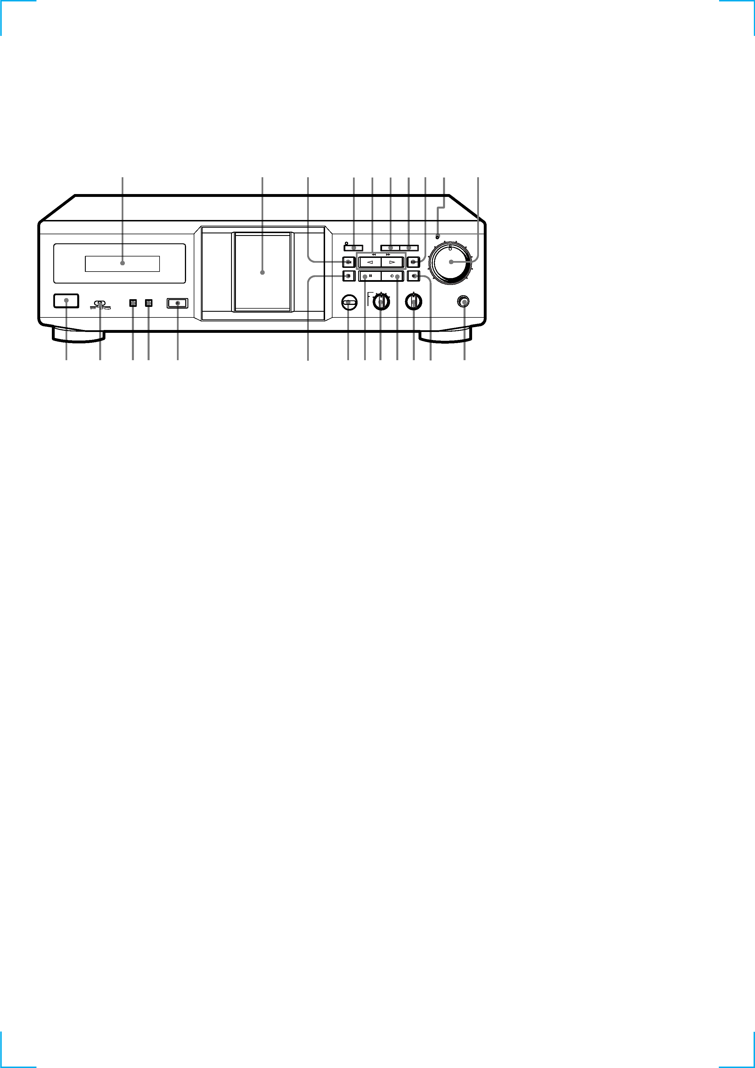
Fluorescent indicator tube
2
Cassette holder
3
m button
4
SYNCHRO button and indicator
5
H button (TC-KE240)
h, H buttons (TC-KE340)
6
FADER button
7
ARL button
8
M button
9
AUTO REC LEVEL indicator
0
RED LEVEL knob
qa
POWER button
qs
DIRECTION MODE button
qd
RESET button
qf
MEMORY button
qg
EJECT button
qh
x button
qj
AUTO CAL button (TC-RE340)
qk
X button
ql
DOLBY NR knob
w;
W button
wa
BALANCE knob
ws
z button
wd
PHONES jack
· LOCATION OF CONTROLS
Front Panel
5
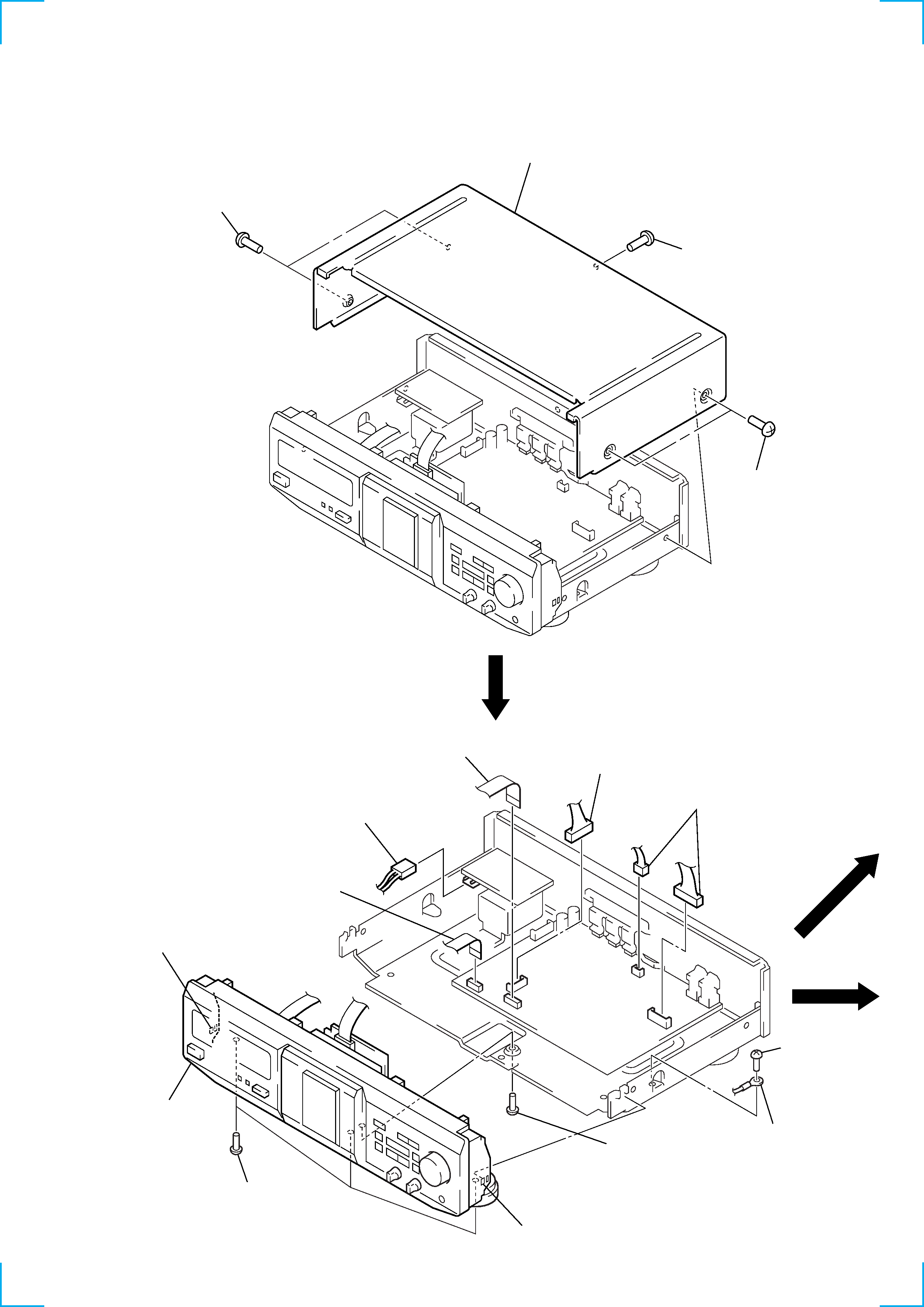
1
wire (flat type)
(CN302)
1
wire (flat type)
(CN801)
6
claw
6
claw
7
front panel
section
5
three screws
(BVTP3
× 8)
5
screw
(BVTT3
× 6)
3
screw
(BVTT3
× 6)
4
harness
2
connector
(CN802)
2
connector
(CN702)
2
two connectors
(CN301, CN803)
CASE (410726)
FRONT PANEL SECTION
Note: Follow the disassembly procedure in the numerical order given.
SECTION 3
DISASSEMBLY
1
two screws
(case 3 TP 2)
3
case (410726)
2
screw (BVTT3
× 6)
1
two screws
(case 3 TP 2)