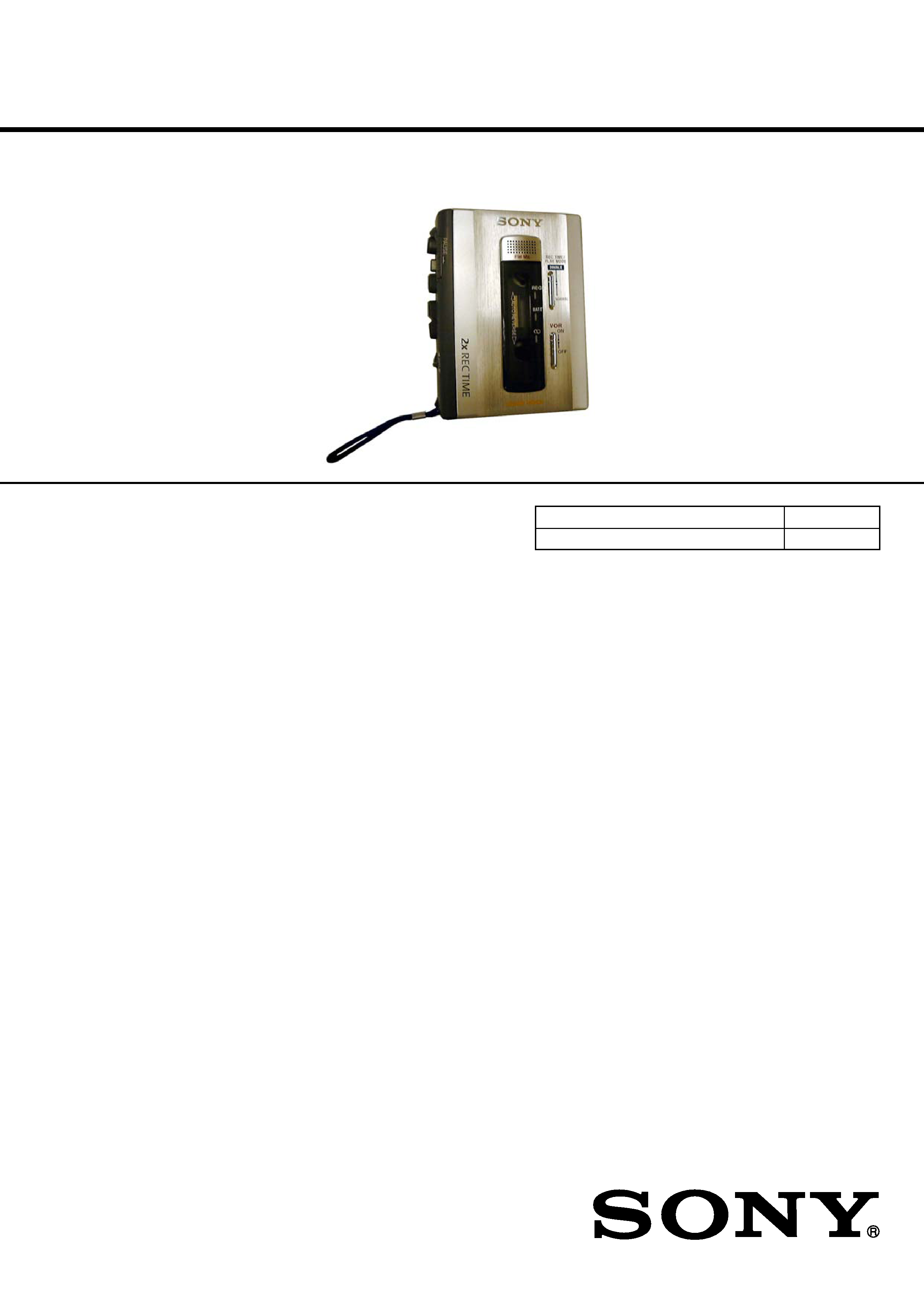
SERVICE MANUAL
CASSETTE-CORDER
US Model
Canadian Model
AEP Model
E Model
Tourist Model
Model Name Using Similar Mechanism
New
Tape Transport Mechanism Type
MT-500-175
SPECIFICATIONS
TCM-500DV
Ver 1.2 2004. 04
Recording system
2-track 1 channel monaural
Tape speed
4.8 cm/s or 2.4 cm/s
Frequency range
350 - 6 300 Hz using nomal (TYPE I) cassette (with REC
TIME/PLAY MODE switch at "NORMAL")
Speaker
Approx. 3.6 cm (1 7 /16 in.) dia.
Power output
450 mW + 450 mW (at 10 % harmonic distortion)
Input
Microphone input jack (minijack)
sensitivity 0.2 mV for 3k
or lower impedance microphone
Output
Earphone jack (minijack) for 8 -300
earphone
Variable range of the tape speed
From approx. +30% to 15% (with REC TIME/PLAY
MODE switch at "NORMAL")
Power requirements
· 3 V DC, batteries AA (R6) x 2
· External DC 3 V power sources
Dimensions (w/h/d) (incl. projecting parts and controls)
Approx. 87.6 x 113.0 x 37.1 mm
(3 1 /2 x 4 1 /2 x 1 1 /2 in.)
Mass (main unit only)
Approx. 215 g (7.6 oz.)
Design and specifications are subject to change without notice.
9-877-111-03
2004D02-1
© 2004.04
Sony Corporation
Personal Audio Company
Published by Sony Engineering Corporation
TCM-500DV
2
TABLE OF CONTENTS
1.
GENERAL ................................................................... 2
2.
SERVICING NOTES ................................................ 2
3.
DISASSEMBLY ......................................................... 3
3-1. Cabinet Rear Assy (500), Lid Assy (500),
Cassette ..................................................................
3
3-2. MAIN Board ..........................................................
4
3-3. Mechanism Deck ...................................................
4
3-4. Head, Magnetic (Rec/PB/Erase) (HRPE901),
Belt (AR), Capstan/Reel (M601) ..........................
5
3-5. LED Board .............................................................
5
3-6. SP Board ................................................................
6
4.
MECHANICAL ADJUSTMENTS ....................... 7
5.
ELECTRICAL ADJUSTMENTS ......................... 7
6.
DIAGRAMS
6-1. Block Diagrams ......................................................
8
6-2. Printed Wiring Board MAIN Board (Side A) ...
9
6-3. Printed Wiring Board MAIN Board (Side B) ... 10
6-4. Schematic Diagram MAIN Board (1/2) ........... 11
6-5. Schematic Diagram MAIN Board (2/2) ........... 12
6-6. Printed Wiring Board LED, SP Board .............. 13
6-7. IC BLOCK DIAGRAMS ....................................... 14
Flexible Circuit Board Repairing
· Keep the temperature of the soldering iron around 270 °C dur-
ing repairing.
· Do not touch the soldering iron on the same conductor of the
circuit board (within 3 times).
· Be careful not to apply force on the conductor when soldering
or unsoldering.
Notes on chip component replacement
· Never reuse a disconnected chip component.
· Notice that the minus side of a tantalum capacitor may be dam-
aged by heat.
SECTION 1
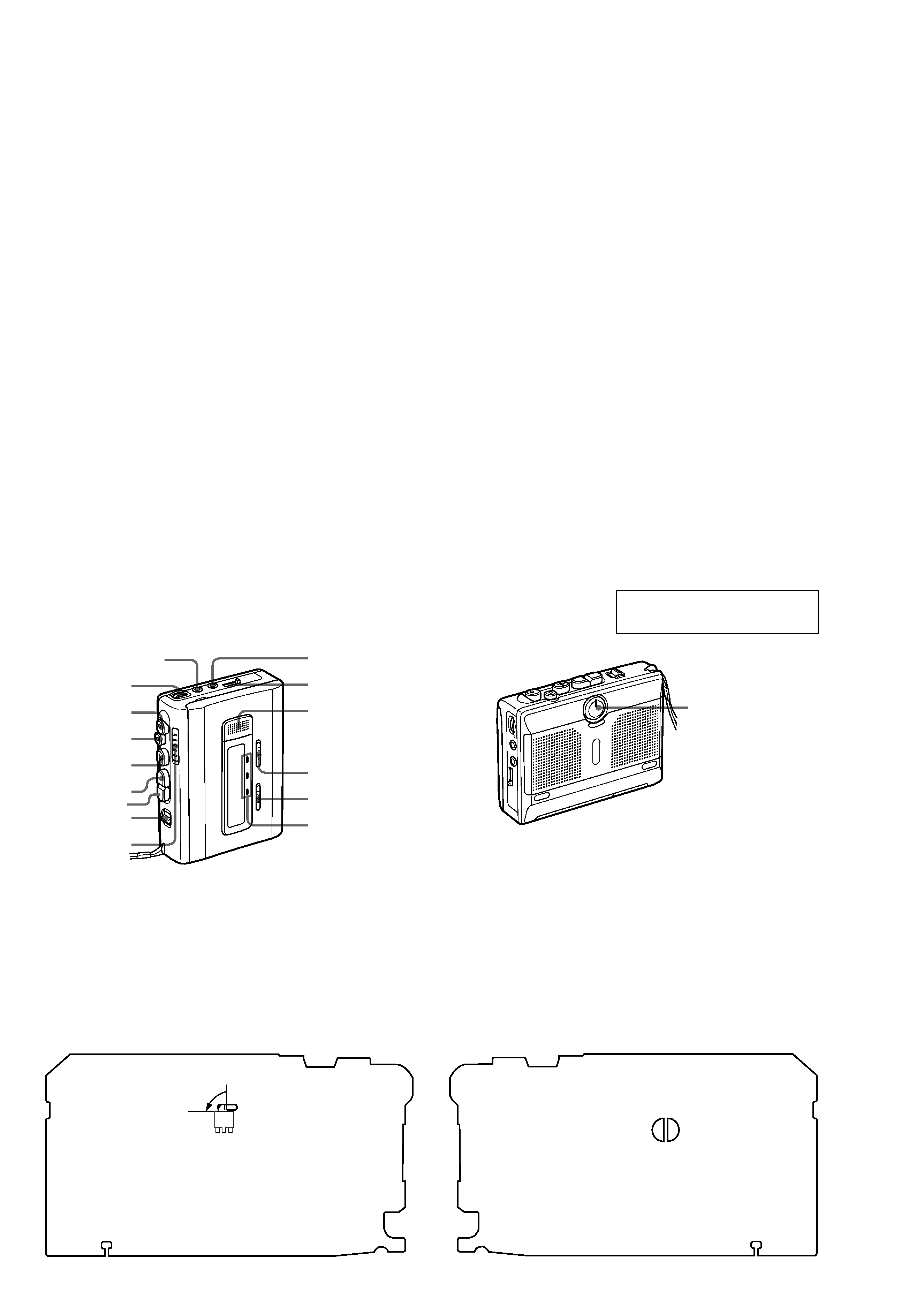
GENERAL
REC TIME/PLAY MODE
VOR
TAPE COUNTER
z REC
x
STOP
REW/REVIEW
FF/CUE
VOL
Flat Mic
Microphone affleurant
PAUSE .
nN
PLAY
n
DIR N
REC, BATT,E lamps
Témoins REC, BATT,E
MIC (PLUG IN POWER)
EAR
SPEED CONTROL
SECTION 2
SERVICING NOTES
In this set, the S102 (POWER) detects REC/PLAYBACK on.
It is mounted on the MAIN board, and therefore the REC/PLAYBACK on cannot be detected with the MAIN board removed.
When making an operation check and voltage check of mechnical deck with the MAIN board removed, fix the S102 at turn on.
S102
ON
*
MAIN BOARD (side A)
MAIN BOARD (side B)
SL101
7.
EXPLODED VIEWS ................................................ 15
7-1. Cabinet Section ...................................................... 15
7-2. Cassette Holder Section ........................................ 16
7-3. Mechanism Deck Section-1 (MT-500-175) .......... 17
7-4. Mechanism Deck Section-2 (MT-500-175) .......... 18
8.
ELECTRICAL PARTS LIST ............................... 19
Also, soldering the lands SL101 bridge makes S102 to turn on.
This section is extracted from
instruction manual.
TCM-500DV
3
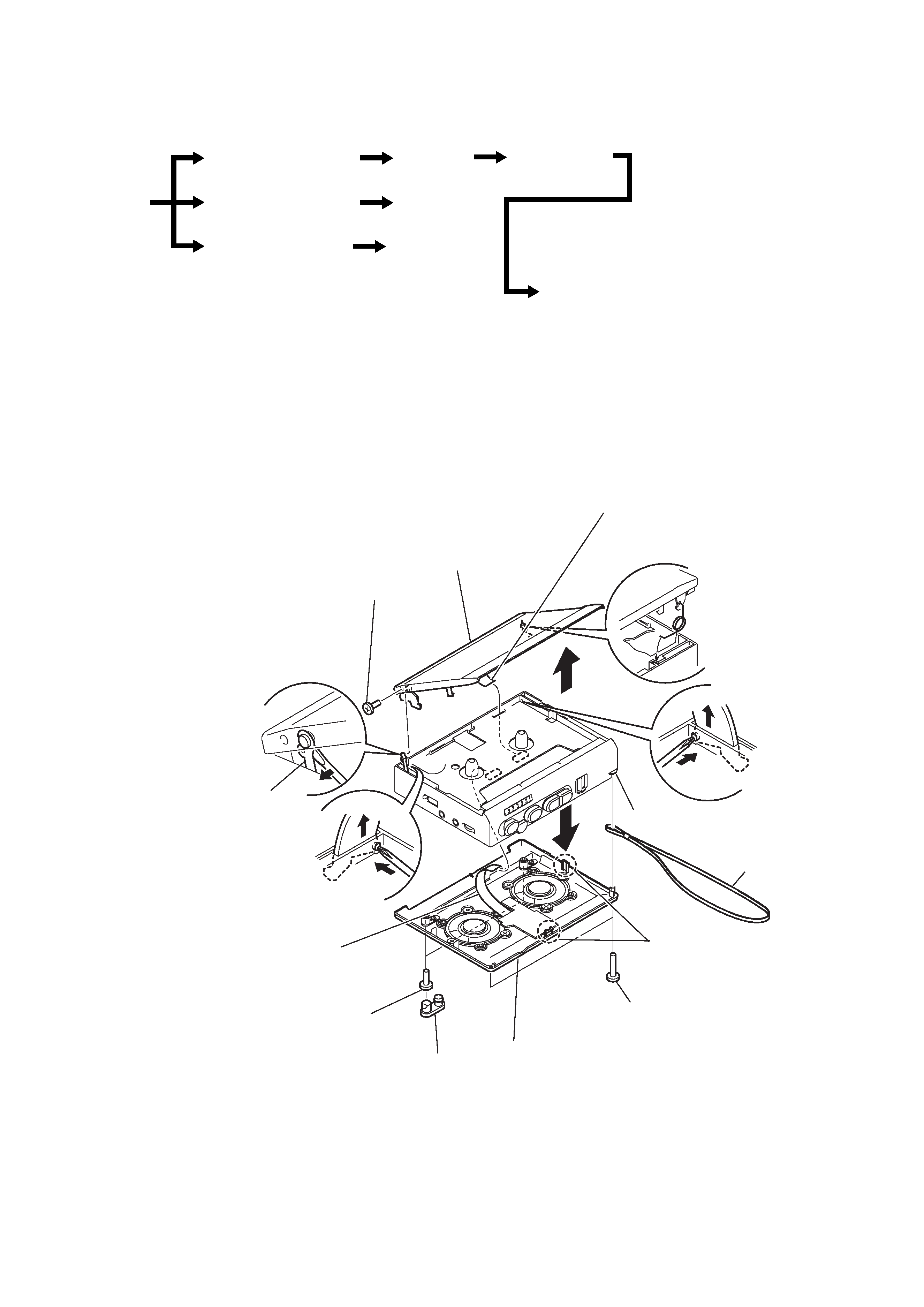
3-1.CABINET REAR ASSY (500), "LID ASSY (500), CASSETTE"
Note: Follow the disassembly procedure in the numerical order given.
SECTION 3
DISASSEMBLY
· This set can be disassembled in the order shown below.
Cabinet (Front) assy (500)
MAIN board
Lid assy (500), Casette
Head, Magnetic (Rec/Pb/Erase) (HRPE901), Belt (AR),
Capstan/Reel Motor (M601)
LED board
SP board
Set
Cabinet Rear assy (500)
Mechanism Deck
qa
5
qg
Lid assy (500), cassette
6
Flexible doard (CN201)
Cabinet (front) assy (500)
2
Screws (B1.7 x 9)
3
Screws (1.7 x 16)
4
Claws
8
Strap, hand
1
Foot (B)
7
Cabinet rear assy (500)
0
Screw (B1.7 x 3)
9
Flexible board (CN401)
Returning lever
Note on Assembling "Lid Assy (500),
Cassette"
On assembling the lid assy (500),
cassette, insert the one side of the l
id spring to the hole on the lid assy,
and fit the other side to the cabinet
(front) assy (500) as shown in the
figure.
qs
Remove the "lid assy (500),
cassette" while pushing the
pivot with a phillips-head
screwdriver or the like.
qd
Remove the returning lever from the
pivot of the "lid assy (500), cassette"
while inserting a screwdriver between
the "lid assy (500), cassette" and the
returning lever.
qf
Remove the "lid assy (500), cassette"
while pushing the pivot with a phillips-
head screwdriver or the like.
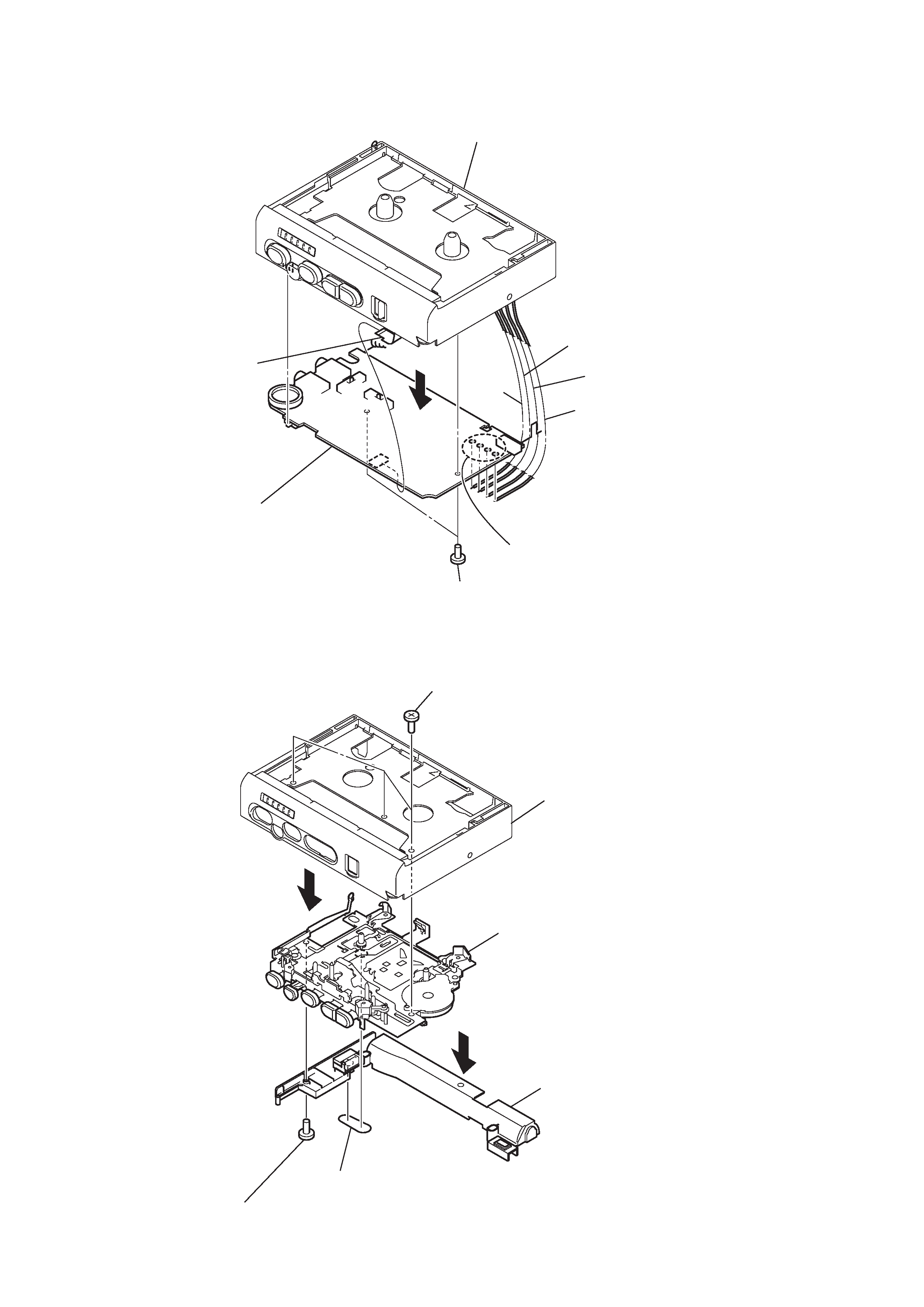
TCM-500DV
4
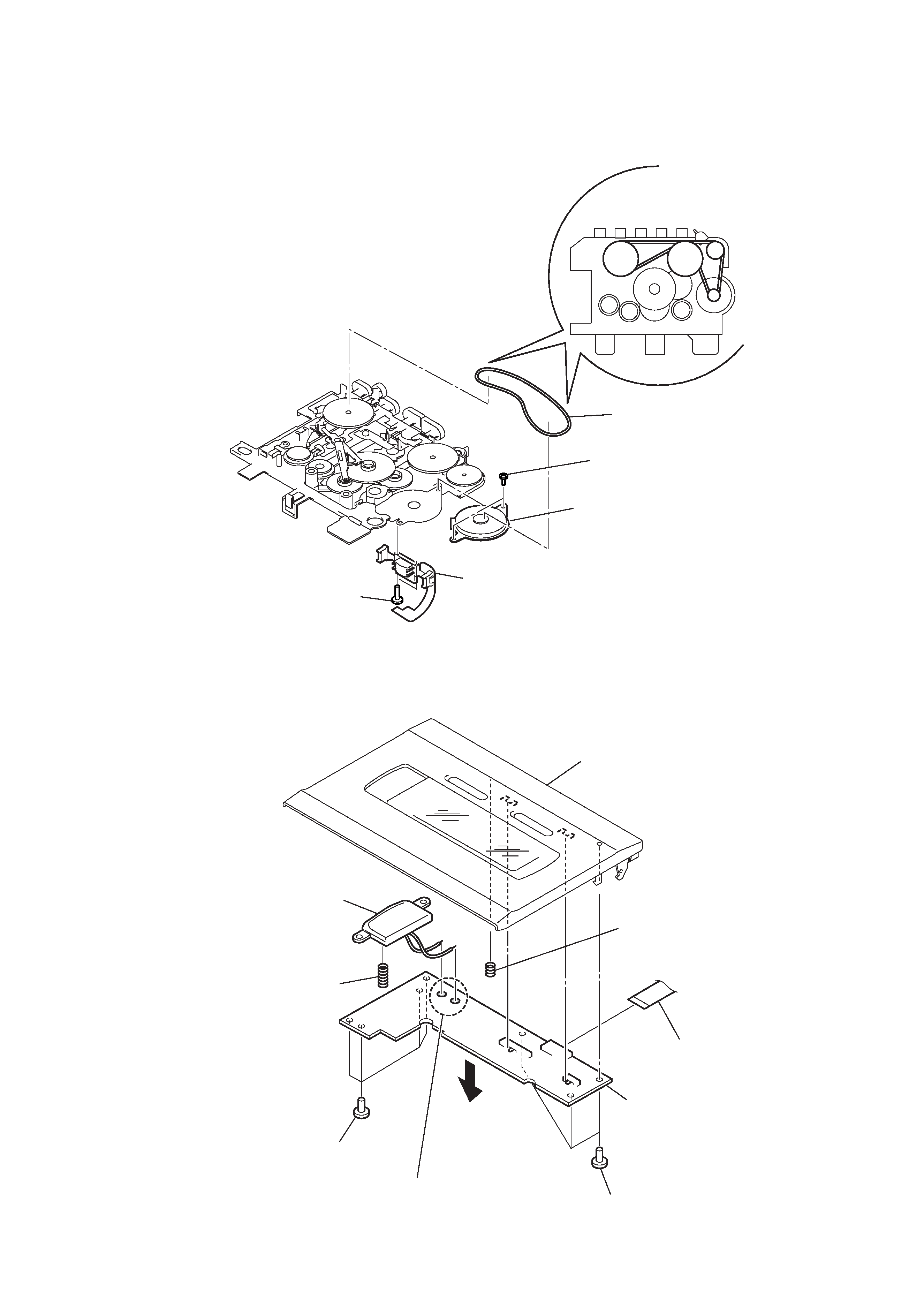
3-3. MECHANISM DECK
6
3
5
Screws (M1.4 x 2.5)
7
Mechanism deck (MT-500-175)
4
Jack (600)
1
Belt (counter)
2
Screw (M1.4 x 2.5)
Cabinet (front) assy (500)
3-2. MAIN BOARD
4
Cabinet (front) assy (500)
Orange
Black
Red
White
1
Remove four solders of capstan/reel motor
3
Screws (M1.4)
5
MAIN board
2
Flexible board (CN101)
TCM-500DV
5
3-4.HEAD, MAGNETIC (REC/PB/ERASE) (HRPE901), BELT (AR), CAPSTAN/REEL MOTOR (M601)
3
Belt (AR)
How to attach a belt
4
Screw (M1.4)
5
Capstan/reel motor (M601)
2
Head, magnetic (rec/pb/erase) (HRPE901)
1
Screw (M1.4)
3
Lid assy (500) cassette
4
Flexible board (CN402)
9
LED board
6
Remove two solders of mic
1
Screws
7
Sprng (500), ground
8
Mic 901
2
Screws
5
Spring (earth)
3-5.LED BOARD