Ver 1.0 1998.09
MICROFILM
TCM-4TR
SERVICE MANUAL
CASSETTE-CORDER
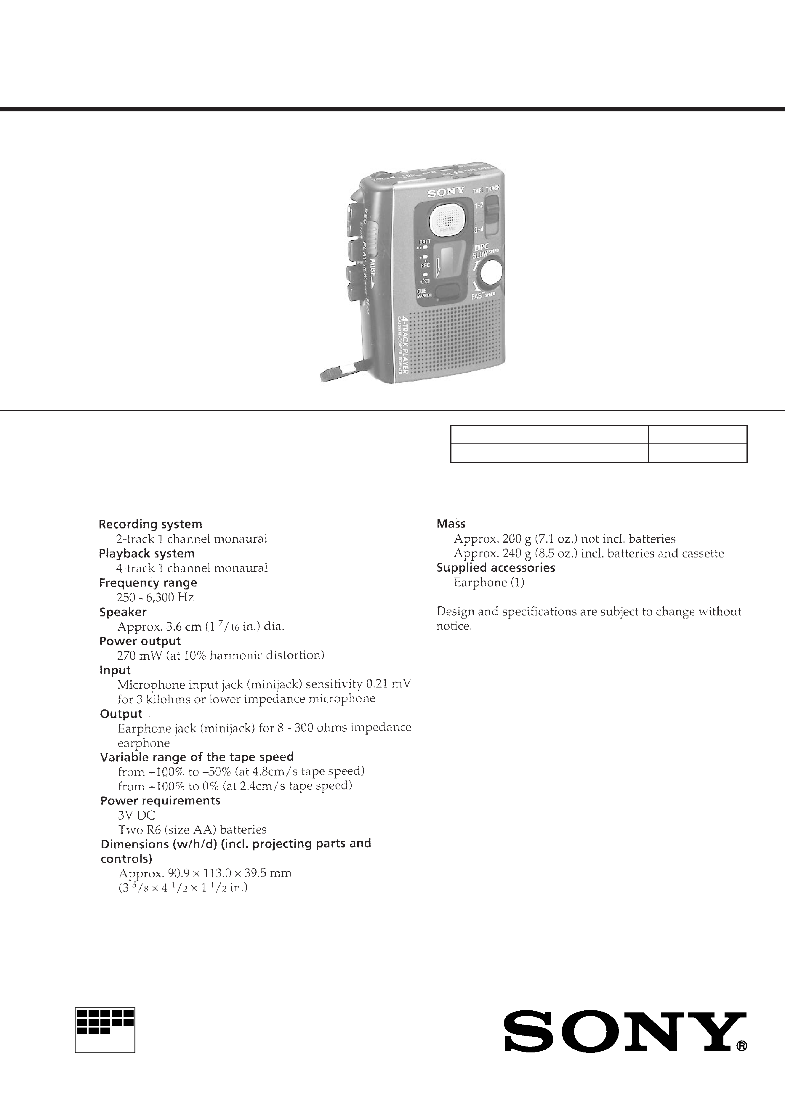
SPECIFICATIONS
US Model
Model Name Using Similar Mechanism
NEW
Tape Transport Mechanism Type
MT-4TR-118
2
Specifications ........................................................................... 1
1. GENERAL
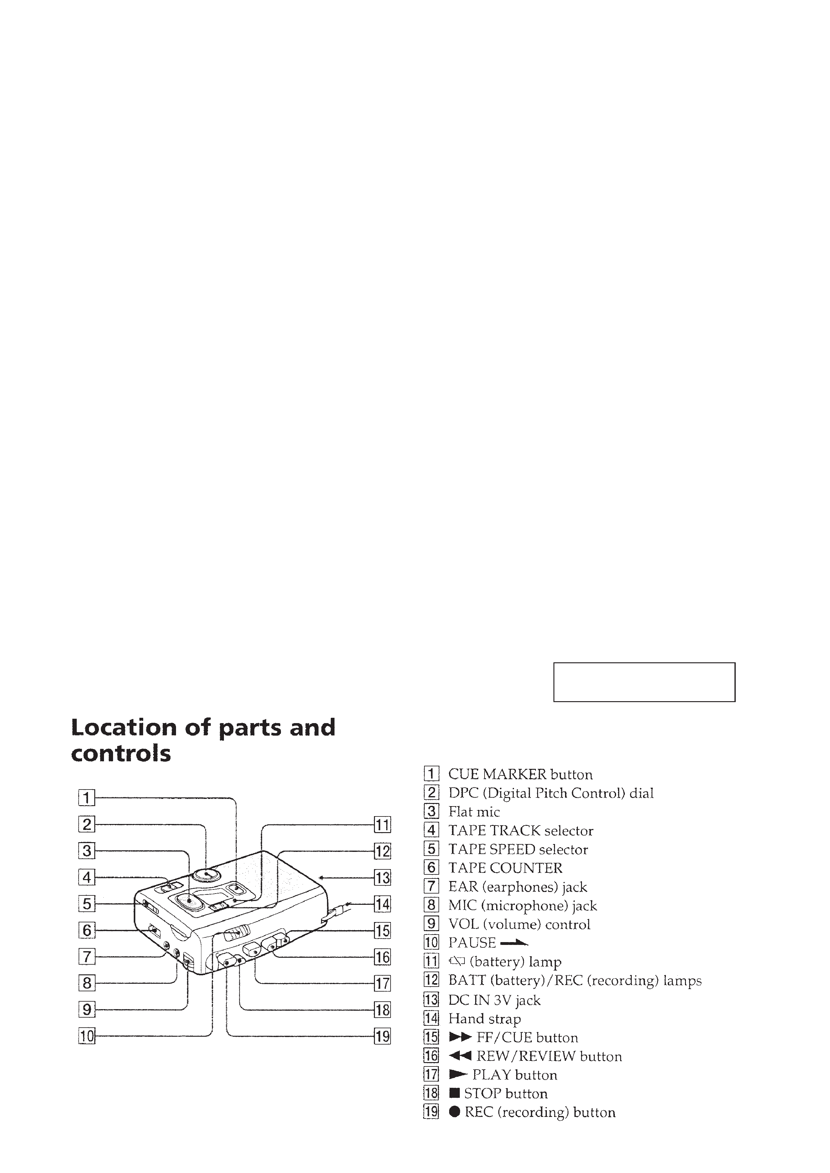
Location of Parts and Controls .......................................... 2
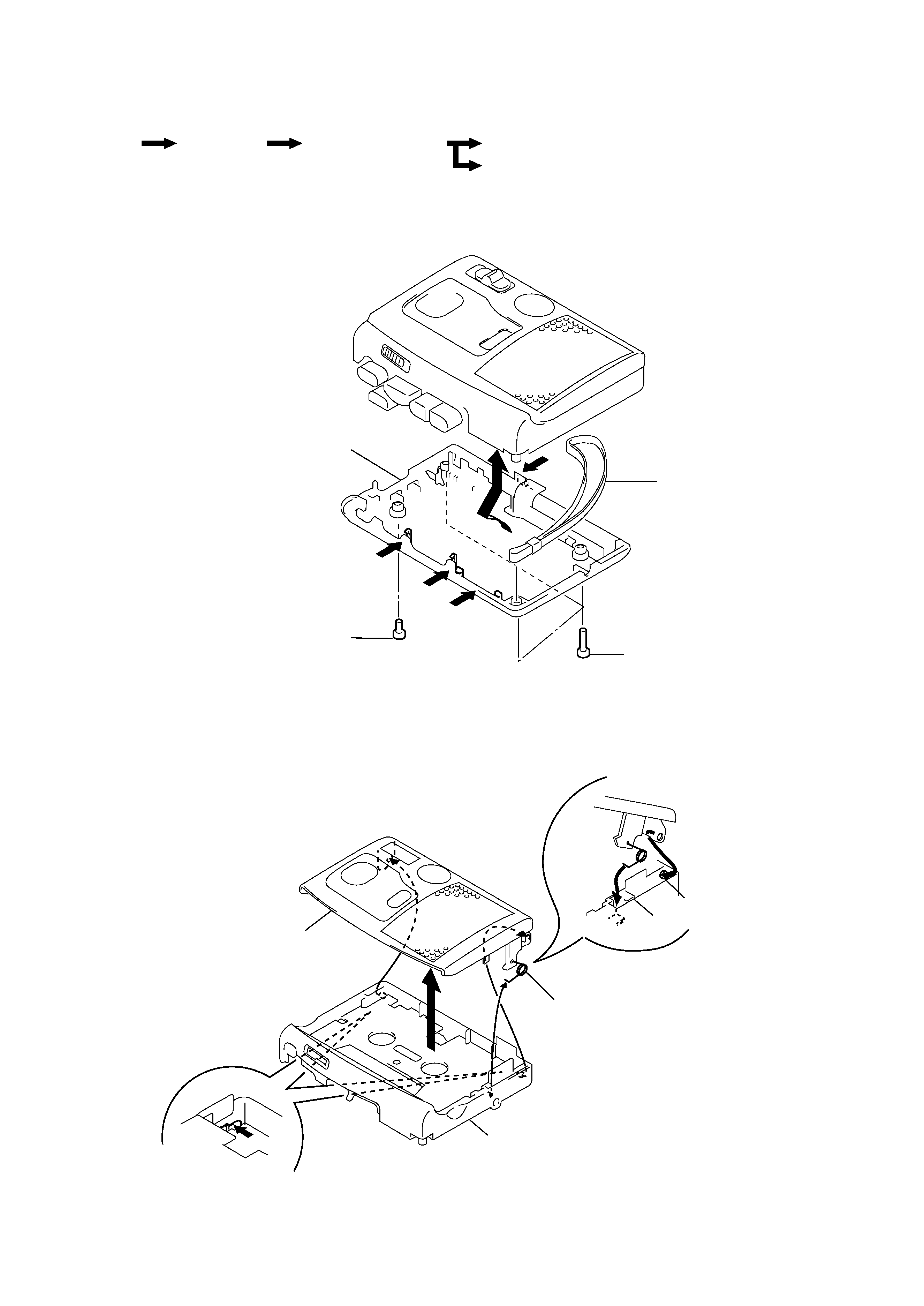
2. DISASSEMBLY
2-1. Cabinet (Rear) ............................................................. 3
2-2. Lid Sub Assy, Cassette ................................................ 3
2-3. Main Board, Mechanism Deck ................................... 4
2-4. DPC Board, SP901, Microphone Assy ....................... 5
3. ADJUSTMENTS
3-1. Mechanical Adjustments ............................................ 6
3-2. Electrical Adjustments ................................................ 6
4. DIAGRAMS
4-1. Explanation of IC Terminals ....................................... 8
4-2. Block Diagrams .......................................................... 9
4-3. Printed Wiring Boards .............................................. 12
4-4. Schematic Diagram ................................................... 17
5. EXPLODED VIEWS
5-1. Cassette lid Section ................................................... 23
5-2. Cabinet Section ......................................................... 24
5-3. Mechanism deck Section -1 ...................................... 25
5-4. Mechanism deck Section -2 ...................................... 26
6. ELECTRICAL PARTS LIST ................................ 27
Flexible Circuit Board Repairing
· Keep the temperature of the soldering iron around 270°C during
repairing.
· Do not touch the soldering iron on the same conductor of the
circuit board (within 3 times).
· Be careful not to apply force on the conductor when soldering
or unsoldering.
Notes on chip component replacement
· Never reuse a disconnected chip component.
· Notice that the minus side of a tantalum capacitor may be dam-
aged by heat.
TABLE OF CONTENTS
SECTION 1
GENERAL
This section is extracted from
instruction manual.
3
SECTION 2
DISASSEMBLY
Note :Followthedisassemblyprocedureinthenumericalordergiven.
2-1. CABINET (REAR)
r
Theequipmentcanberemo
vedusingthef
ollo wingpr ocedure .
1 Screws (B1.7x9)
2 Screw (1.4)
3
3
3
Strap
Cabinet (Rear)
3
4
Cabinet (Rear)
Lid sub ASSY, Cassette
Main board, Mechanism deck
DPC board, SP901, Microphone ASSY
Set
2-2. LID SUB ASSY, CASSETTE
2
Cabinet (Front) ASSY
Lid sub ASSY, Cassette
Boss
3 Spring, Cassette
Cabinet (Front) ASSY
A
1 Press on the left & right
clips from the rear of the
Cabinet (Front) ASSY ,
and remove the Boss.
· Use caution when installing the
"Lid sub ASSY, Cassette".
Install the "Lid sub ASSY,
Cassette" with the "Spring,
Cassette" as shown in
A in the
drawing so that it fits into the
holes on the Cabinet (Front)
ASSY . Once installed, fit the
left and right pieces on.
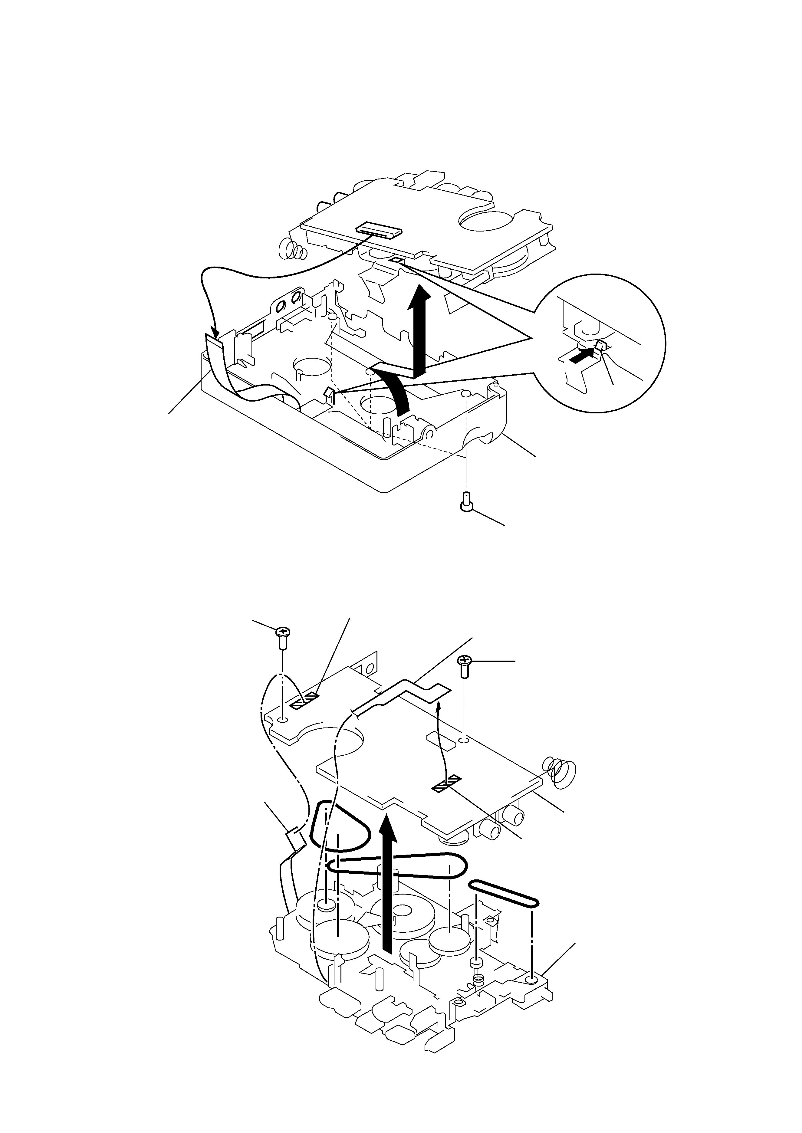
4
7 Screw (B1.7x5)
8 Screw (M1.4x3)
9
Main board
6 Remove solder
5 Remove solder
Mechanism deck
Motor flexible board
Head flexible board
2-3. MAIN BOARD, MECHANISM DECK
Claw
2 DPC connection
flexible board
Cabinet (Front) ASSY
4
3
1 Screws (IB lock), Pan
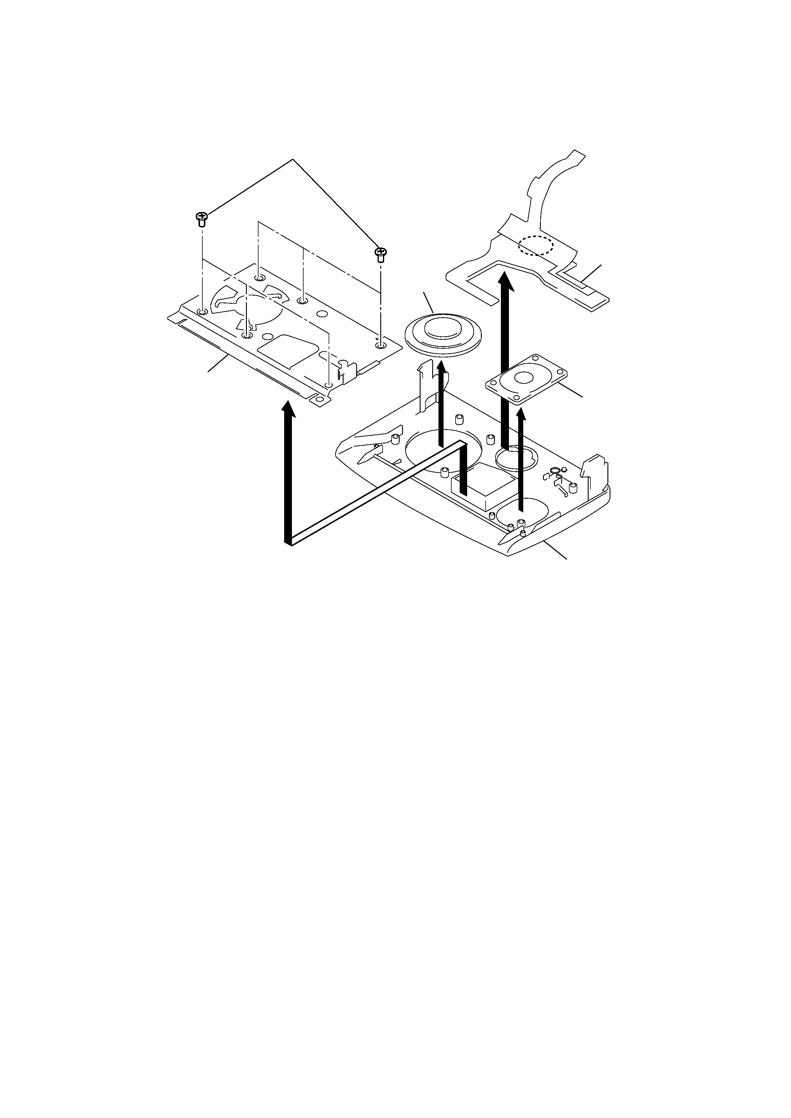
5
2
Lid sub ASSY, Cassette
Cover
3 DPC board
4 SP901
1 Screws (1.7x3)
5 Microphone ASSY
2-4. DPC BOARD, SP901, MICROPHONE ASSY