MICROFILM
SERVICE MANUAL
CASSETTE-CORDER
US Model
Canadian Model
AEP Model
E Model
Tourisit Model
Model Name Using Similar Mechanism
NEW
Tape Transport Mechanism Type
MT-459V-118
SPECIFICATIONS
TCM-465V
2
Flexible Circuit Board Repairing
· Keep the temperature of the soldering iron around 270 °C dur-
ing repairing.
· Do not touch the soldering iron on the same conductor of the
circuit board (within 3 times).
· Be careful not to apply force on the conductor when soldering
or unsoldering.
Notes on chip component replacement
· Never reuse a disconnected chip component.
· Notice that the minus side of a tantalum capacitor may be dam-
aged by heat.
SECTION 1
GENERAL
TABLE OF CONTENTS
1.
GENERAL ................................................................... 2
2.
DISASSEMBLY ......................................................... 3
3.
MECHANICAL ADJUSTMENTS ....................... 5
4.
ELECTRICAL ADJUSTMENTS ......................... 6
5.
DIAGRAMS
5-1. Block Diagram ................................................................ 7
5-2. Printed Wiring Boards .................................................... 9
5-3. Schematic Diagram ......................................................... 13
6.
EXPLODED VIEWS ................................................ 16
7.
ELECTRICAL PARTS LIST ............................... 20
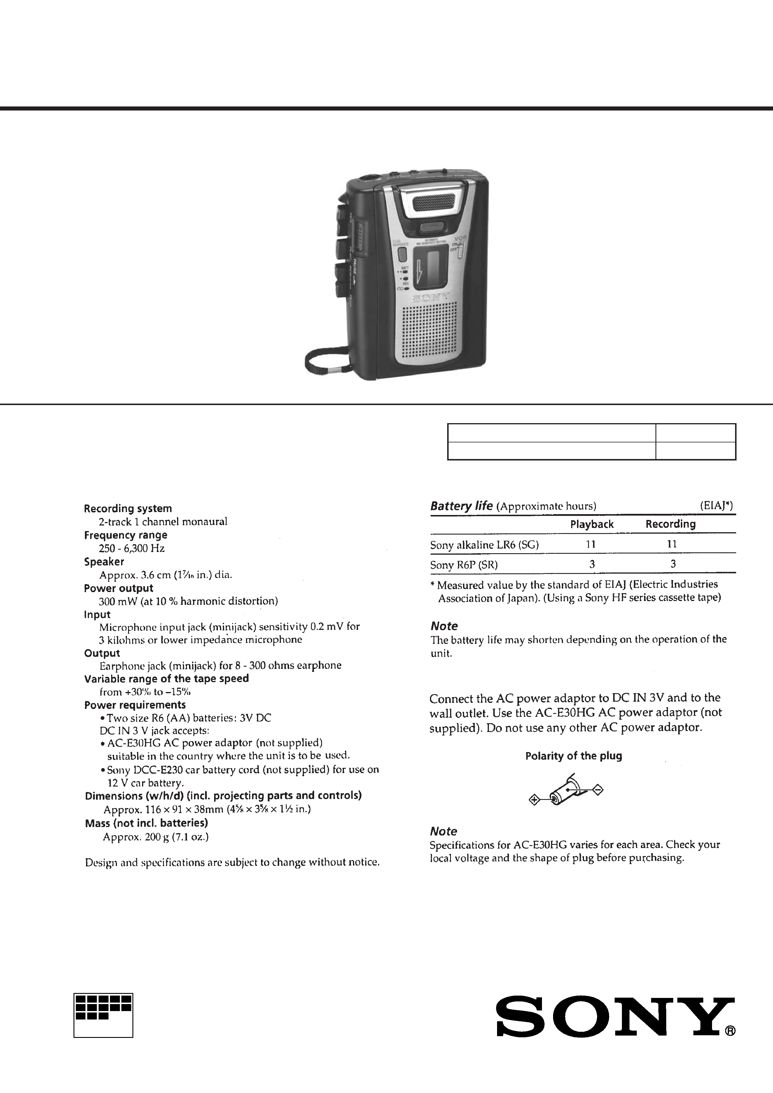
· Location of Controls
EAR
TAPE COUNTER
MICROPHONE
VOL
rREC
pSTOP
(PLAY
SPEED CONTROL
0REW/REVIEW
)FF/CUE
PAUSEc
POP-UP MIC SWITCH
VOR
CUE MARKER
BATT/REC
DC IN 3V
MIC
3
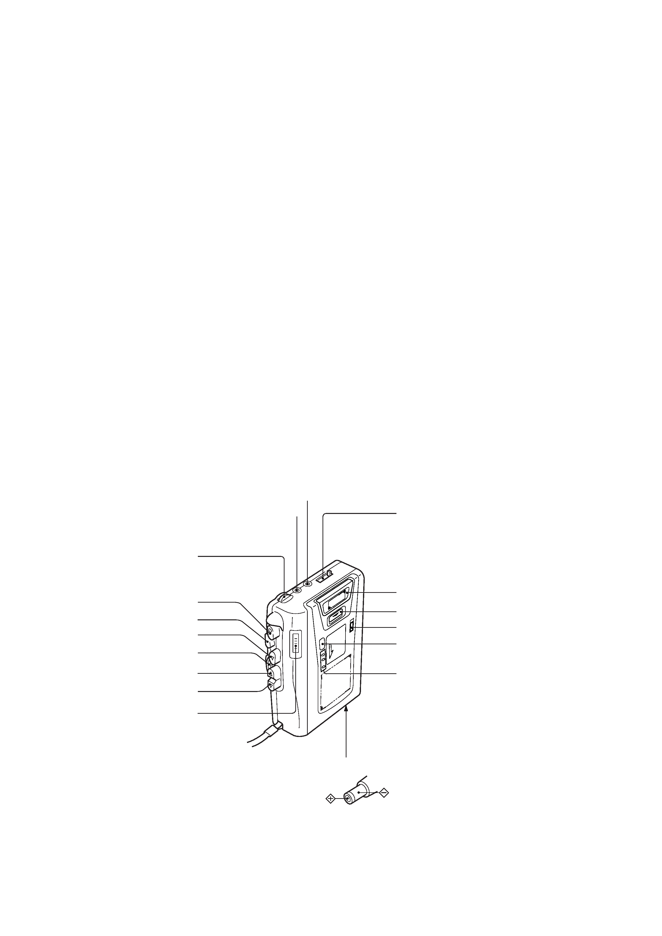
CABINET (REAR) , CASSETTE LID
SECTION 2
DISASSEMBLY
Note: Follow the disassembly procedure in the numerical order given.
· This set can be disassembled in the order shown below.
SET
CABINET (REAR)
CASSETTE LID
MECHANISM DECK
(MT-459V-118)
MAIN BOARD
BELT
8 cassette lid
1 three screws
(B1.7
× 10)
2 screw
(IB lock)
3 two claws
3 claw
7 boss
4 cabinet (rear)
3 claw
5 strap
7 boss
9 cassette spring
6 flexible board
(CN102)
4
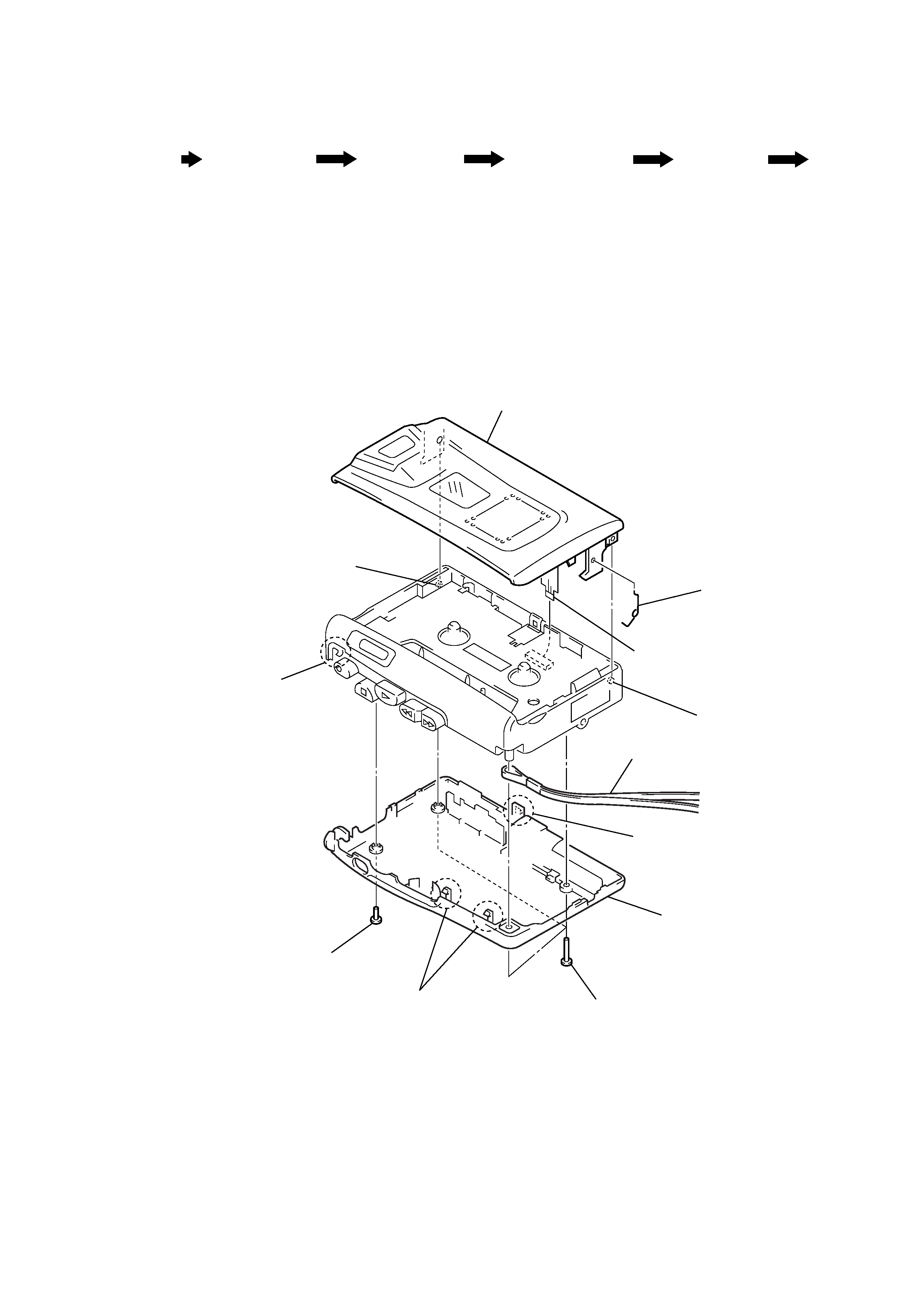
MECHANISM DECK (MT-459V-118)
MAIN BOARD
Note: On installation MAIN board
adjust the S105 and
knob (pause).
Note: On installation MAIN board
adjust the S101 and REC lever.
2 claw
1 three screws
(IB lock)
knob (pause)
3 Remove the mechanism deck
(MT-459V-118) and MAIN board
to direction of the arrow
A.
A
S105
2 screw
(1.7)
3 screw
(M1.4)
1 Remove four solders of the
head lead (HRP901) and
motor leads (M901).
4 MAIN board
S101
REC lever
5
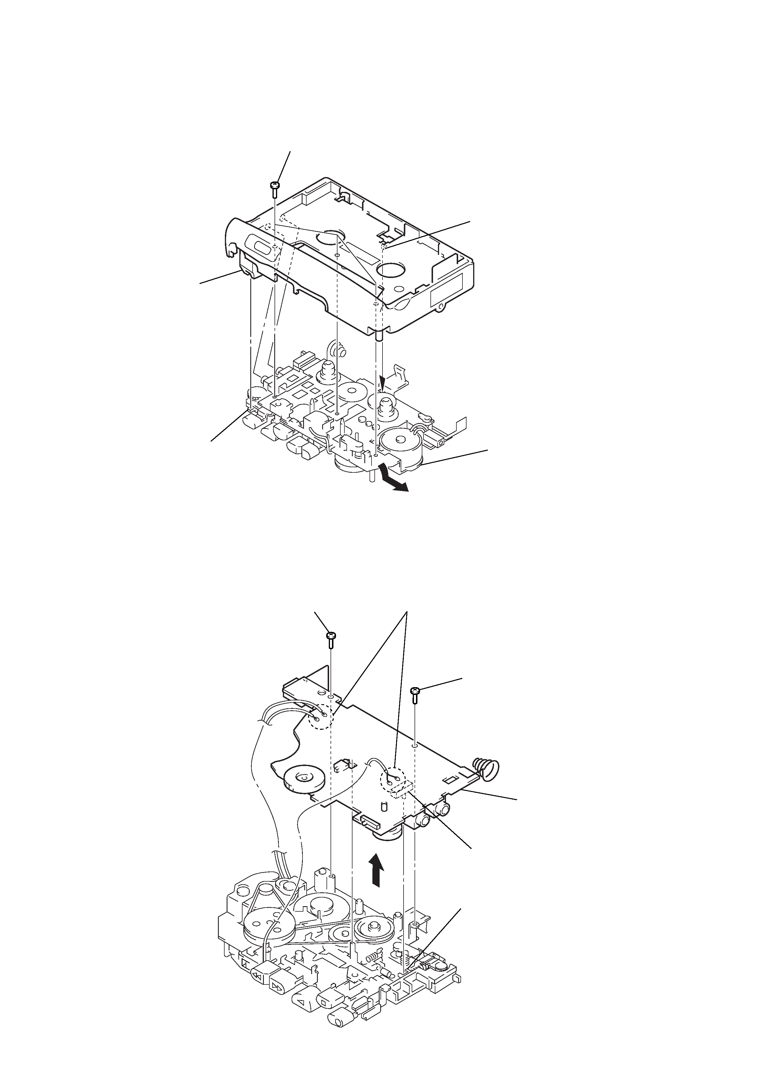
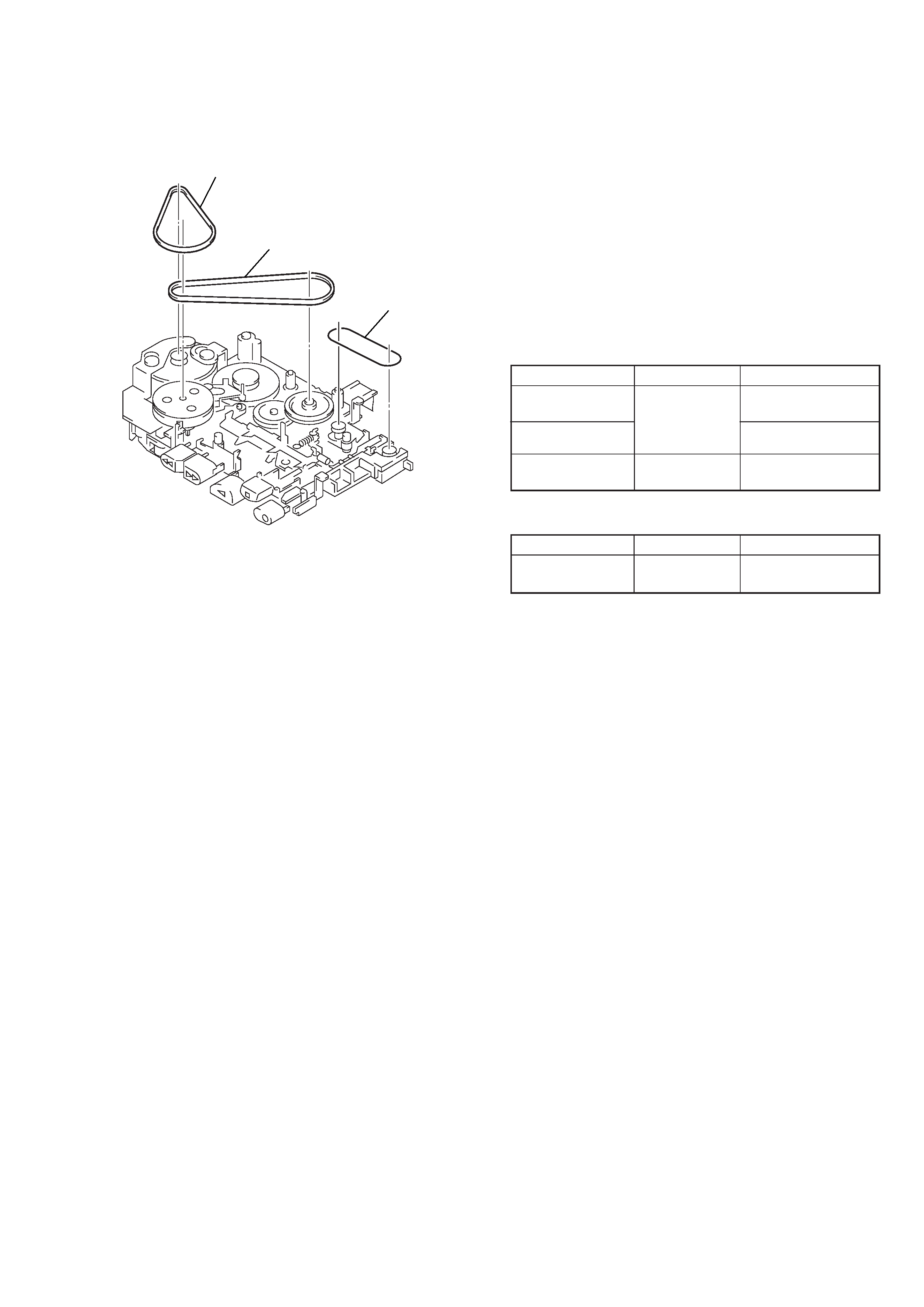
BELT
SECTION 3
MECHANICAL ADJUSTMENTS
Tape Tension Measurement
1. Clean the following parts with a denatured-alcohol-moistened
swab:
record/playback head
pinch roller
erase head
rubber belt
capstan
idler
2. Demagnetize the record/playback head with a head demagne-
tizer. (Do not bring the head demagnetizer close to the erase
head.)
3. Do not use a magnetized screwdriver for the adjustments.
4. After the adjustments, apply suitable locking compound to the
parts adjusted.
5. The adjustments should be performed with the rated power
supply voltage (2.5 V) unless otherwise noted.
Torque Measurement
Mode
Torque Meter
Meter Reading
FWD
22 48 g·cm
CQ-102C
(0.31 0.67 oz·inch)
Forward Back
1.0 4.5 g·cm
Tension
(0.014 0.063 oz·inch)
FF, REW
CQ-201B
more than 50 g·cm
(more than 0.69 oz·inch)
Mode
Tension Meter
Meter Reading
FWD
CQ-403C
more than 50 g
(more than 1.76 oz)
1 capstan belt
2 FR belt
3 counter belt