TCM-450DV
US Model
Canadian Model
AEP Model
E Model
Chinese Model
Tourist Model
SERVICE MANUAL
CASSETTE-CORDER
Sony Corporation
Personal Audio Company
Published by Sony Engineering Corporation
9-877-551-03
2004G02-1
© 2004.07
SPECIFICATIONS
Ver 1.2 2004. 07
Model Name Using Similar Mechanism
New
Tape transport Mechanism Type
MT-450-175
Recording system
2-track 1 channel monaural
Speaker
Approx. 3.6 cm (1 7/
16 in.) dia.
Tape speed
4.8 cm/s (1 7/
8 ips) or 2.4 cm/s (
15/
16 ips)
Variable range of the tape speed
From approx. +30% to 20% (with REC TIME/PLAY MODE
switch at "NORMAL")
Frequency range
250 - 6,300 Hz using nomal (TYPE I) cassette
(with REC TIME/PLAY MODE switch at "NORMAL")
Input
Microphone input jack (minijack/ monaural/PLUG IN POWER)
sensitivity 0.2 mV for 3 k
or lower impedance microphone
Output
Earphone jack (minijack/ monaural) for 8 - 300
earphone
Power output (at 10 % harmonic distortion)
450 mW
Power requirements
3 V DC, batteries R03 (AAA) x 2/
External DC 3 V power sources
Dimensions (w/h/d) (incl. projecting parts and controls)
Approx. 86.3 x 113.4 x 28.9 mm
(3 1/
2 x 4
1/
2 x 1
3/
16 in.)
Mass (main unit only)
Approx. 173 g (6.2 oz.)
Supplied accessory
Carrying pouch (1)
Design and specifications are subject to change without notice.
2
TCM-450DV
TABLE OF CONTENTS
1.
GENERAL ................................................................... 2
2.
DISASSEMBLY .......................................................... 3
2-1. Cabinet (Rear) ......................................................... 3
2-2. Main Board ............................................................. 4
2-3. Mechanism Deck (MT-450-175) ............................. 4
2-4. Belt (Counter), Belt (Cap)S,
M901 (Capstan/Reel Motor), HRP901
(REC/PB Head), HE901 (ERASE HEAD) ............. 5
2-5. Cassette Lid Assy, Led Board ................................. 5
3.
MECHANICAL ADJUSTMENTS ....................... 6
4.
ELECTRICAL ADJUSTMENTS ......................... 6
5.
DIAGRAMS
5-1. Block Diagrams ....................................................... 7
5-2. Printed Wiring Board MAIN Section (Side A) .. 8
Printed Wiring Board MAIN Section (Side B) .. 9
5-3. Schematic Diagram MAIN Section (1/2) ........... 10
5-4. Schematic Diagram MAIN Section (2/2) ........... 11
5-5. IC BLOCK DIAGRAMS ........................................ 12
6.
EXPLODED VIEWS
6-1. Cassette Lid, Cabinet (Rear) Section ...................... 13
6-2. Cabinet (Front) Section ........................................... 14
6-3. Mechanism Deck Section-1 (MT-450-175) ............ 15
6-4. Mechanism Deck Section-2 (MT-450-175) ............ 16
7.
ELECTRICAL PARTS LIST ................................ 17
Flexible Circuit Board Repairing
· Keep the temperature of the soldering iron around 270 °C dur-
ing repairing.
· Do not touch the soldering iron on the same conductor of the
circuit board (within 3 times).
· Be careful not to apply force on the conductor when soldering
or unsoldering.
Notes on chip component replacement
· Never reuse a disconnected chip component.
· Notice that the minus side of a tantalum capacitor may be dam-
aged by heat.
SECTION 1
GENERAL
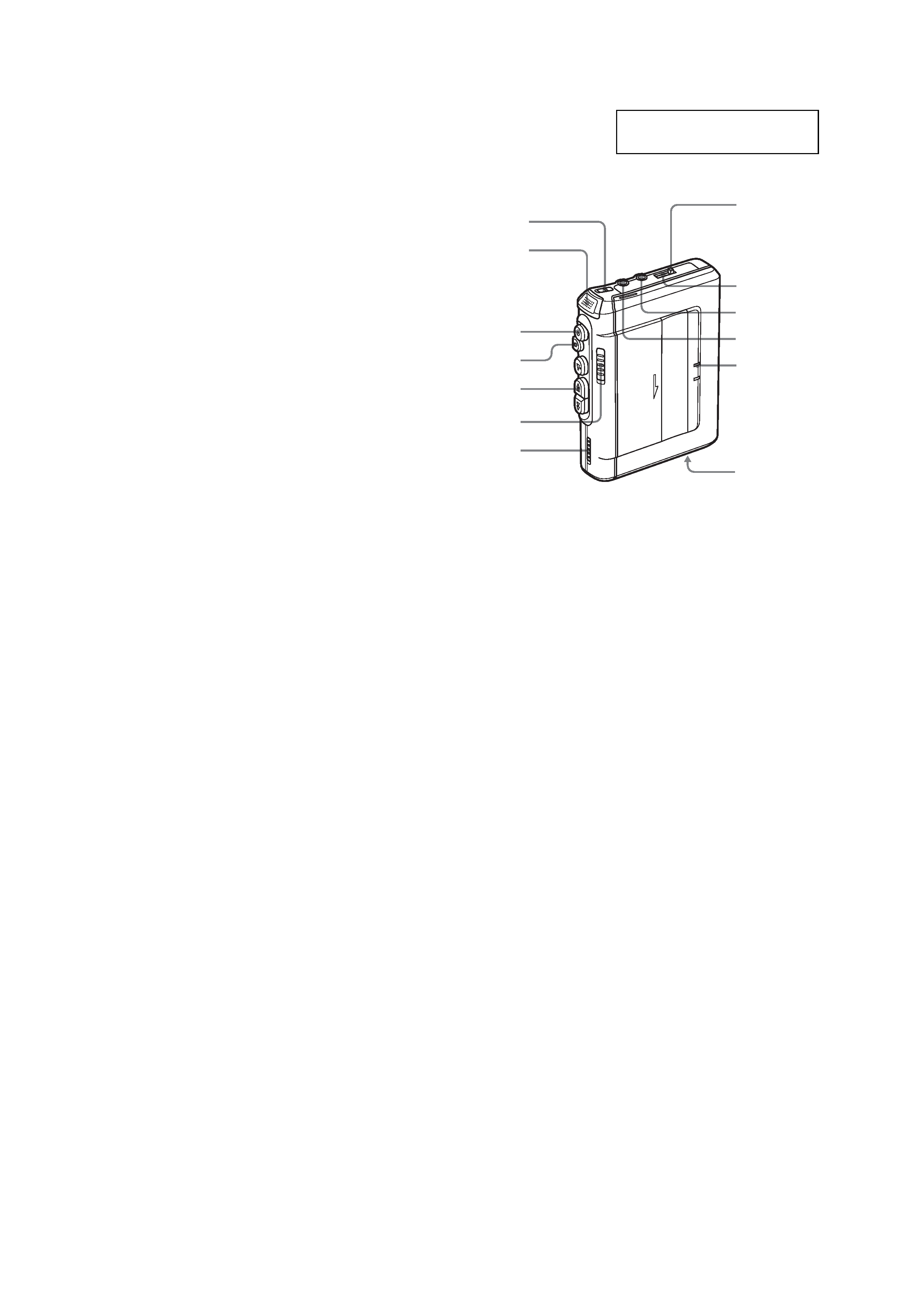
This section is extracted from
instruction manual.
REC/BATT
REC TIME/
PLAY MODE*
VOR
TAPE COUNTER
x STOP
m REW/REVIEW
PAUSE.
MIC (PLUG
IN POWER)*
EAR
Microphone
DC IN 3V
z REC
Tape counter
reset button
* The button/jack has a tactile dot.
3
TCM-450DV
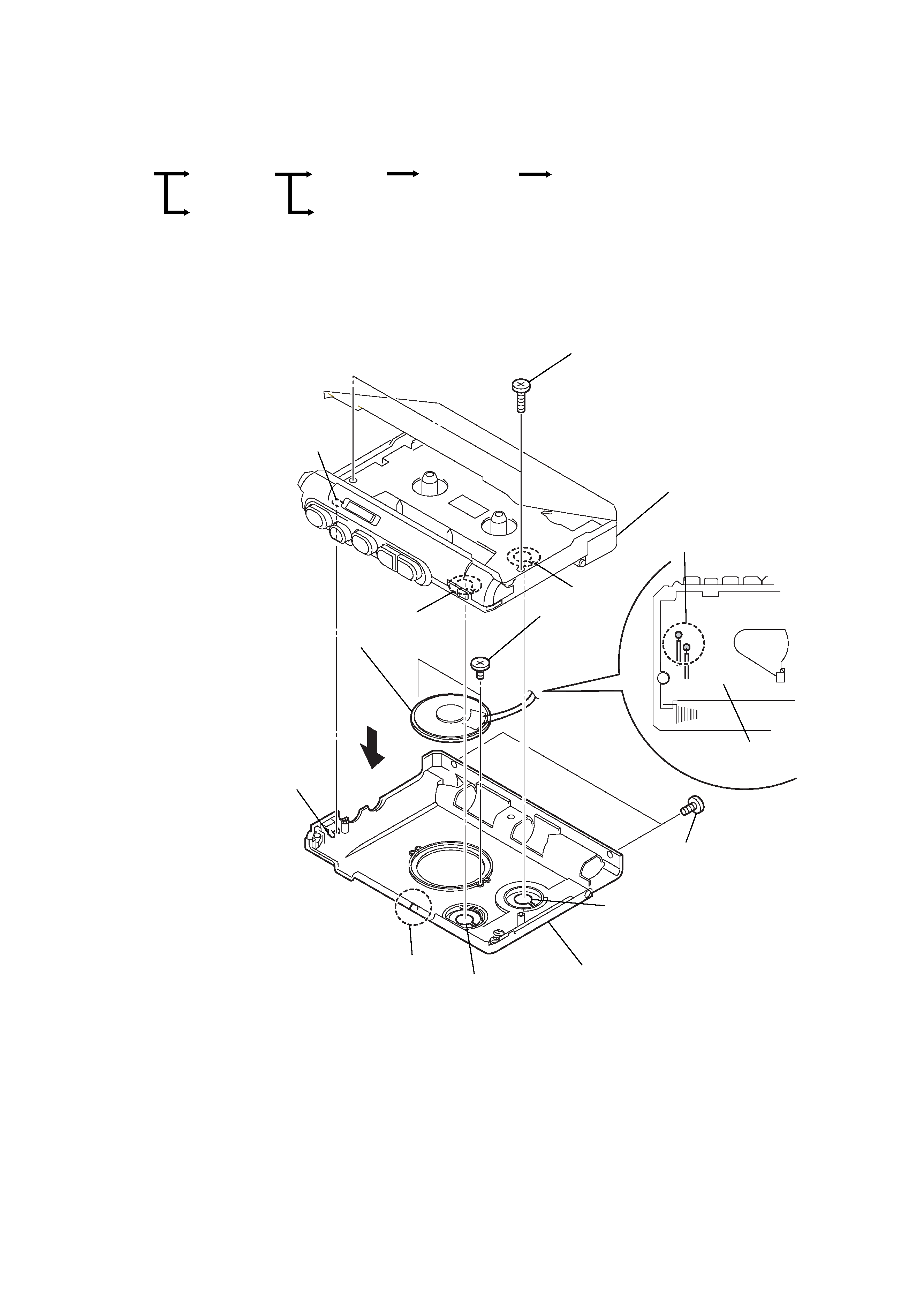
SECTION 2
DISASSEMBLY
· This set can be disassembled in the order shown below.
2-1. CABINET (REAR)
Note: Follow the disassembly procedure in the numerical order given.
Cassette lid assy, LED board
Cabinet (front)
Main board
Belt (Counter), Belt (CAP) S, M901 (Capstan/reel motor),
HRP901 (REC/PB head), HE901 (ERASE head)
Set
Mechanism deck
Cabinet (Rear)
1
two screws (B1.7 X 9)
7
speaker (SP1)
2
two screws (1.7 X 3)
8
cabinet (rear)
cabinet (front)
6
two screws
(B2.0)
5
Remove solder on MAIN board
(two places)
3
claw
4
MAIN board
S501
RV101
RV201
knob (speed) sub assy
knob (VOL)
knob (VOR)
· On installation cabinet (rear),
adjust the S501 and knob (VOR).
· On installation cabinet (rear),
adjust the RV201 and knob
(speed) sub assy.
· On installation cabinet (rear),
adjust the RV101 and knob
(VOL).
4
TCM-450DV
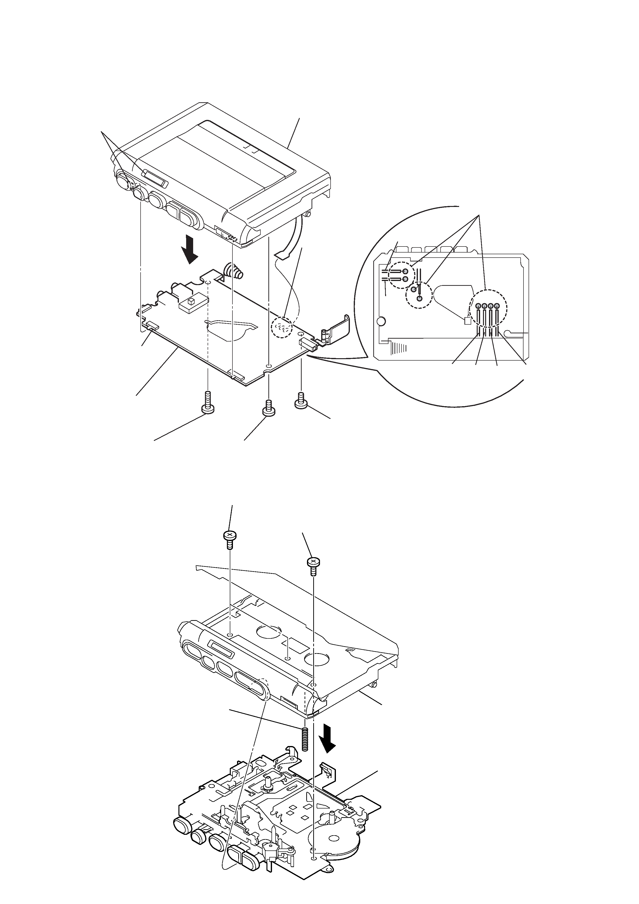
2-2.
MAIN BOARD
GRY
ORG
BLK
BLK
RED
RED
3
screw (B1.7 X 9)
7
MAIN board
4
screw (1.4 X 3)
5
screw (1.4 X 4.5)
cabinet (front)
1
Remove solder
(three places)
2
Remove solder
(eight places)
6
S301
knob (pause)
· On installation MAIN board,
adjust the S301 and knob (pause).
2-3.
MECHANISM DECK (MT-450-175)
1
two screws (M1.4)
2
screw
5
spring (ground)
cabinet (front)
4
mechanism deck
(MT-450-175)
3
5
TCM-450DV
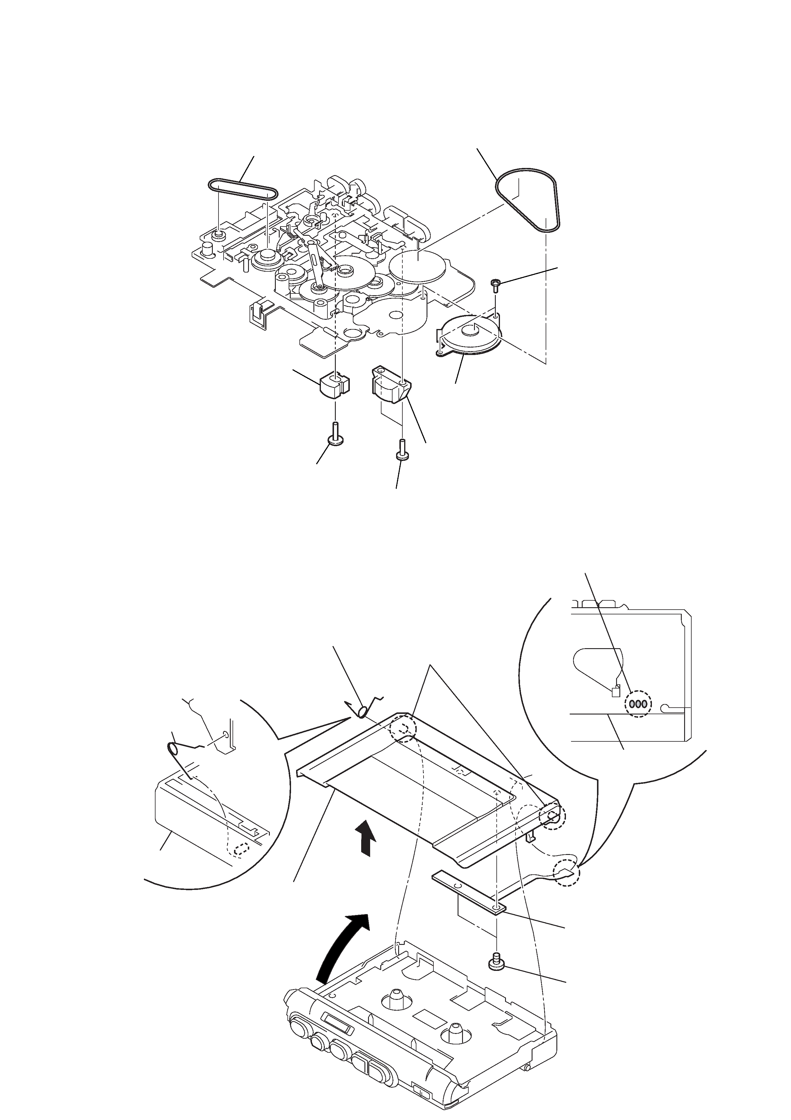
2-4. BELT (COUNTER), BELT (CAP) S, M901 (CAPSTAN/REEL MOTOR), HRP901 (REC/PB HEAD),
HE901 (ERASE HEAD)
1
belt (counter)
2
belt (CAP) S
3
two screws (M1.4X1.4)
5
two screws (M1.4X1.4)
7
screw (M1.4X4.5)
6
HRP901(REC/PB head)
8
HE901 (ERASE head)
4
M901 (capstan/reel motor)
2-5. CASSETTE LID ASSY, LED BOARD
· Install the cassette lid assy with
the cassette-up spring as shown
in the figure so that it fits into the
holes on the casstte lid assy.
2
4
1
Remove solder on MAIN board
(three places)
MAIN board
3
projection
5
cassette-up spring
6
cassette lid assy
7
two screws (M1.4)
8
LED board
cassette lid assy
cassette-up spring
cabinet (front)