MICROFILM
SERVICE MANUAL
Ver 1.1 2000. 03
With SUPPLEMENT 1 (9-926-970-81)
CASSETTE-CORDER
US Model
Canadian Model
AEP Model
E Model
Model Name Using Similar Mechanism
TCM-36
Tape Transport Mechanism Type
MT-40-118
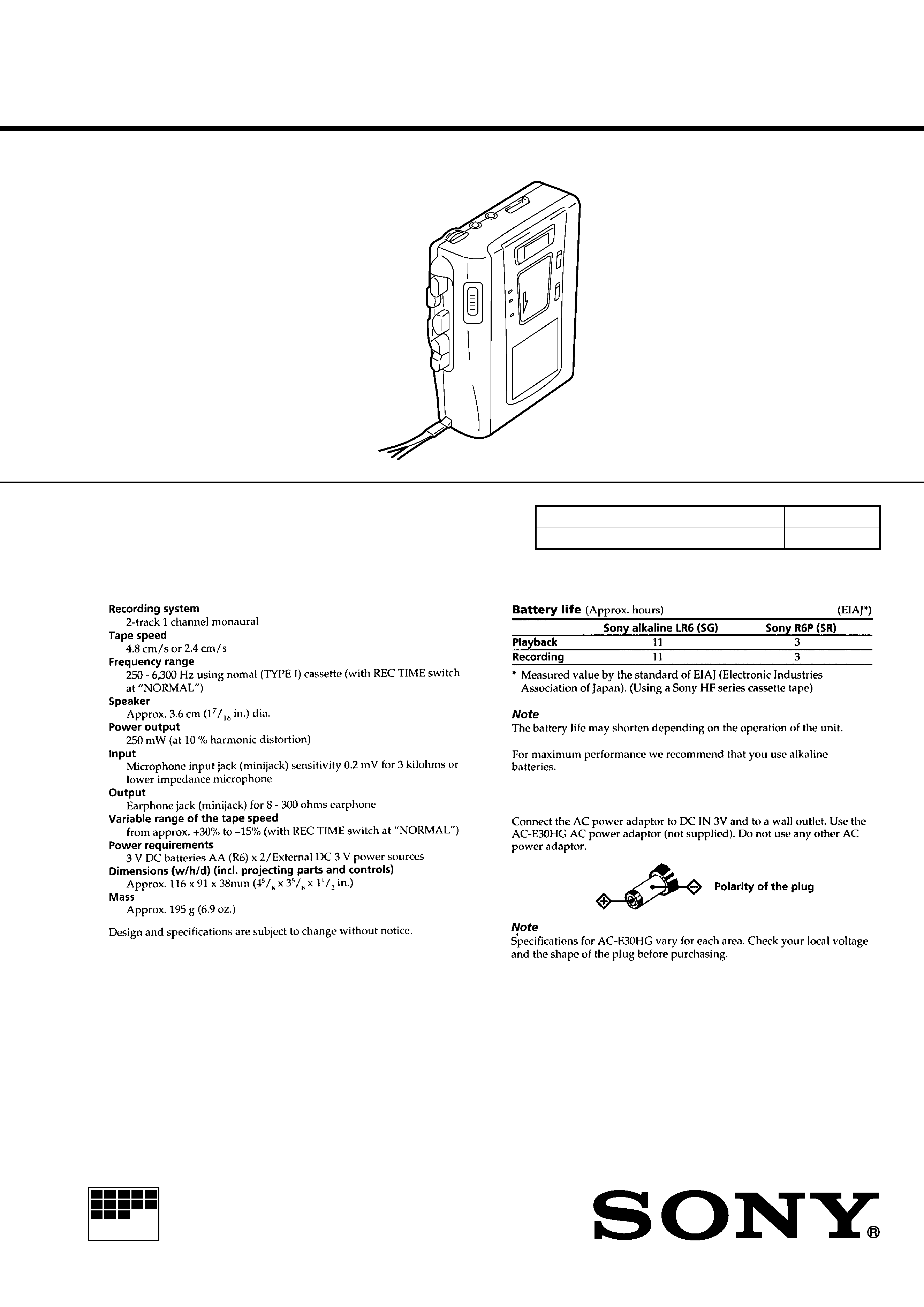
SPECIFICATIONS
TCM-40DV
2
TABLE OF CONTENTS
1.
SERVICING NOTES ............................................... 2
2.
GENERAL ................................................................... 3
3.
DISASSEMBLY ......................................................... 4
4.
MECHANICAL ADJUSTMENTS ....................... 6
5.
ELECTRICAL ADJUSTMENTS ......................... 7
6.
DIAGRAMS
6-1. Block Diagram ................................................................
8
6-2. Printed Wiring Boards .................................................... 10
6-3. Schematic Diagram ......................................................... 13
7.
EXPLODED VIEWS ................................................ 19
8.
ELECTRICAL PARTS LIST ............................... 22
Flexible Circuit Board Repairing
· Keep the temperature of the soldering iron around 270 °C dur-
ing repairing.
· Do not touch the soldering iron on the same conductor of the
circuit board (within 3 times).
· Be careful not to apply force on the conductor when soldering
or unsoldering.
Notes on chip component replacement
· Never reuse a disconnected chip component.
· Notice that the minus side of a tantalum capacitor may be dam-
aged by heat.
SECTION 1
SERVICING NOTES
In this set, the S102 (POWER) detects REC/PLAYBACK on.
It is mounted on the MAIN board, and therefore the REC/PLAY-
BACK on cannot be detected with the MAIN board removed.
When making an operation check and voltage check of mechani-
cal deck with the MAIN board removed, fix the S102 at turn on.
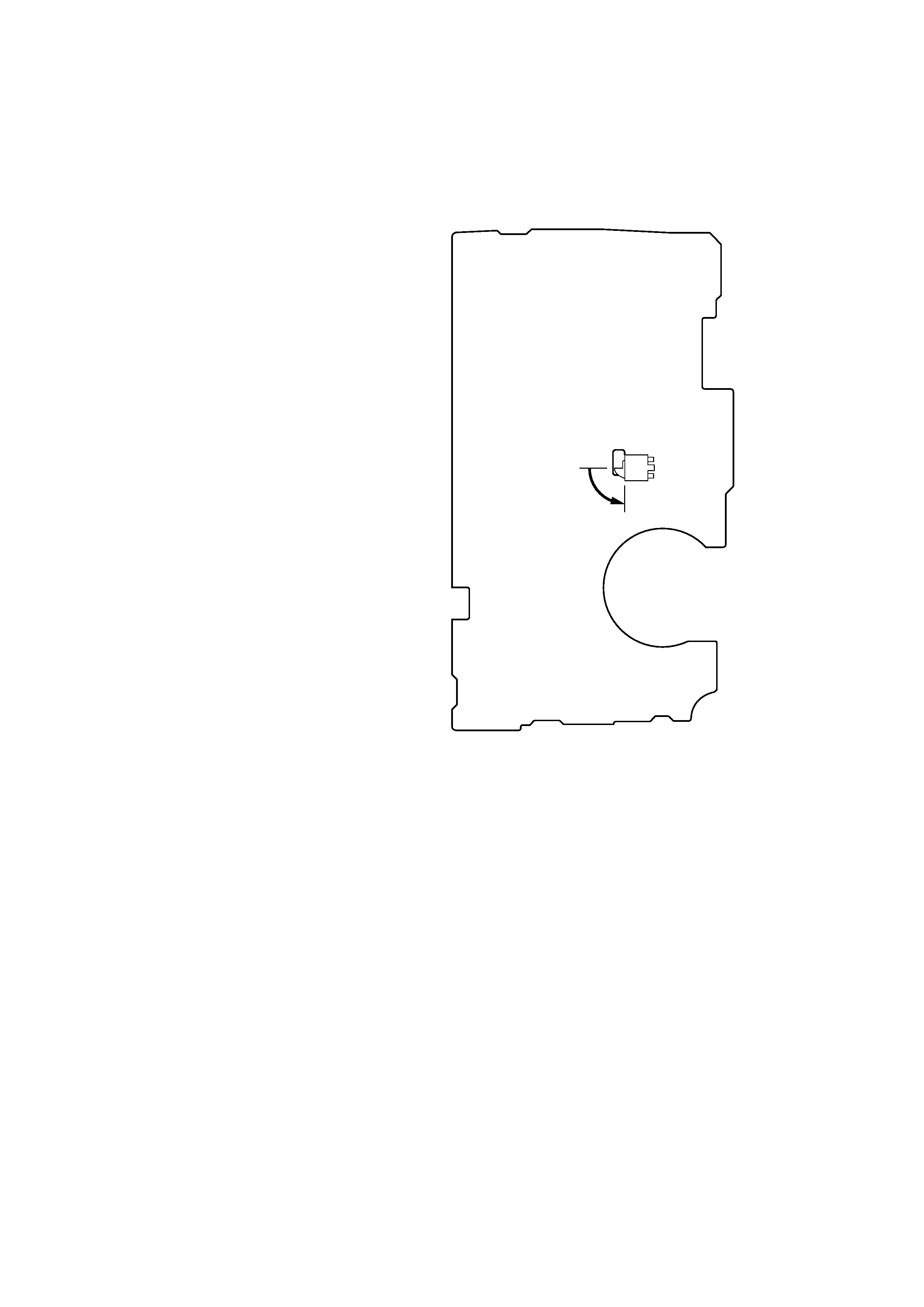
MAIN BOARD (Conductor Side)
S102
on
3
SECTION 2
GENERAL
This section is extracted from
instruction manual.
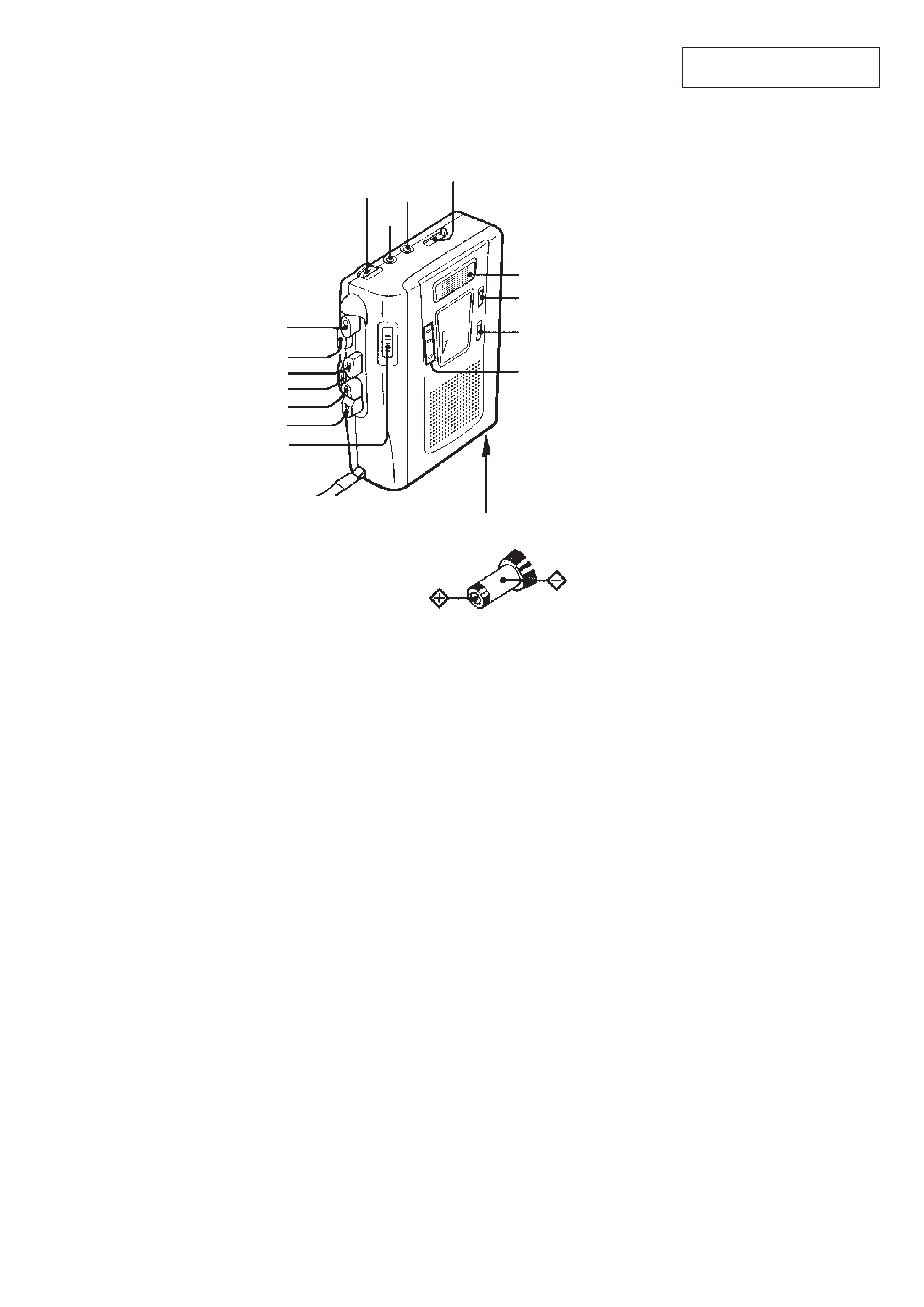
· Location of Controls
VOL
MIC
EAR
TAPE COUNTER
Flat mic
Micropohone plat
REC TIME
VOR
BATT/REC/
i
DC IN 3 V
rREC
pSTOP
9PLAY
PAUSEc
)FF/CUE
SPEED CONTROL
0REW/REVIEW
4
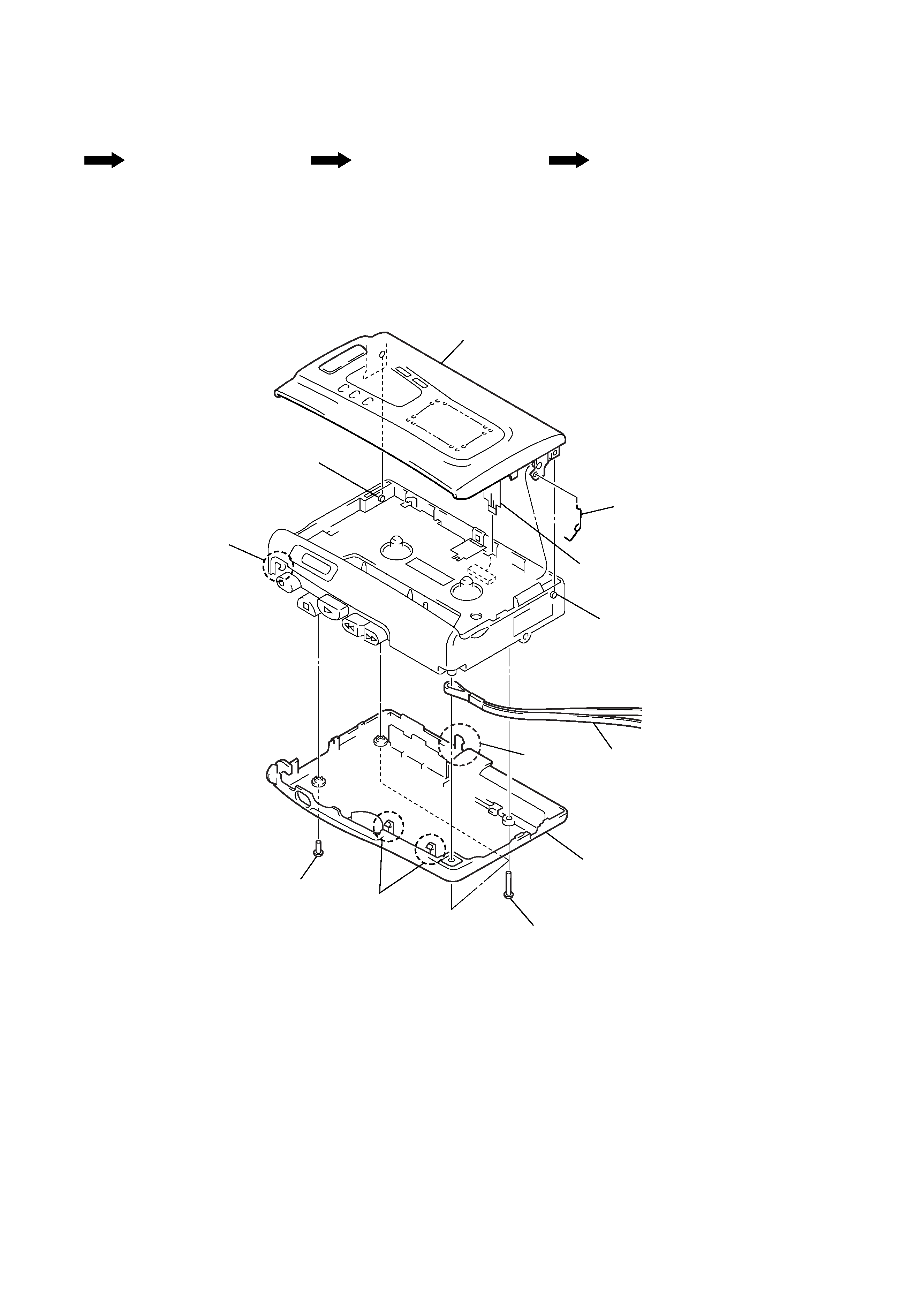
CABINET (REAR), CASSETTE LID
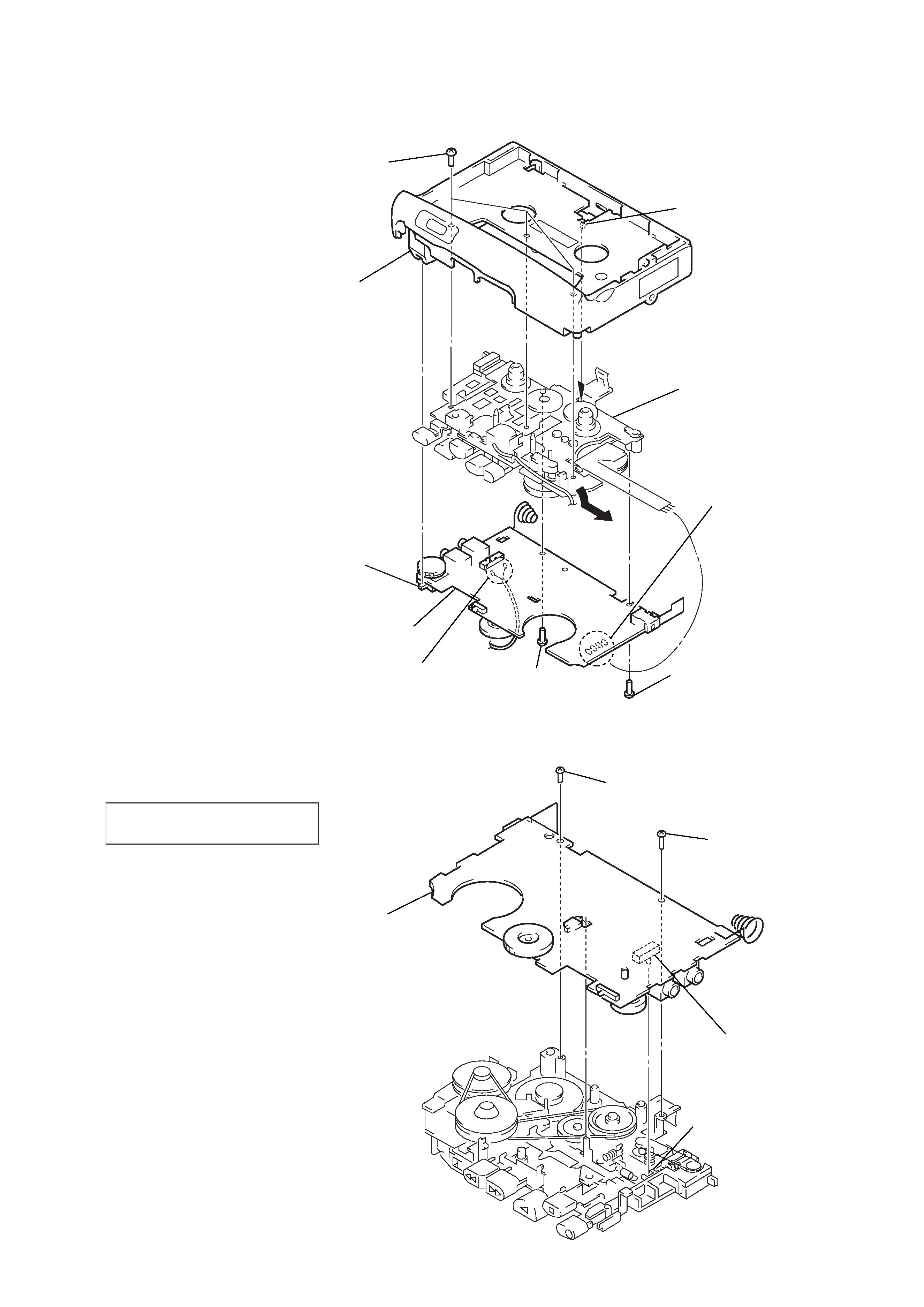
Note: Follow the disassembly procedure in the numerical order given.
SECTION 3
DISASSEMBLY
· This set can be disassembled in the order shown below.
Set
Cabinet (Rear), Cassette Lid
MAIN Board, Mechanism Deck
(MT-40-118)
Belt
8 cassette lid
5 strap
3 two claws
3 claw
2 screw
4 cabinet (rear)
1 three screws (B1.7
× 10)
7 boss
7 boss
6 flexible board
(CN102)
9 cassette spring
3 claw
5
MAIN BOARD, MECHANISM DECK (MT-40-118)
NOTE FOR INSTALLATION
· MAIN BOARD
On installation MAIN board
adjust the S101 and REC lever.
7 claw
3 screw
(1.7)
4 screw
(M1.4)
5 MAIN board
8 mechanism deck
(MT-40-118)
6 three screws
(IB lock)
button (pause)
2 Remove the two solders
of the head lead (HRP901).
1 Remove four solders
of motor leads (M901).
S105
Note: On installation MAIN
board adjust the S105
and button (pause).
REC lever
screw
(1.7)
S101
screw
(M1.4)
MAIN board