SERVICE MANUAL
CASSETTE-CORDER
US Model
Canadian Model
AEP Model
E Model
Chinese Model
TCM-459V
Tourist Model
TCM-36/459V
Model Name Using Similar Mechanism
NEW
Tape Transport Mechanism Type
MT-459V-118
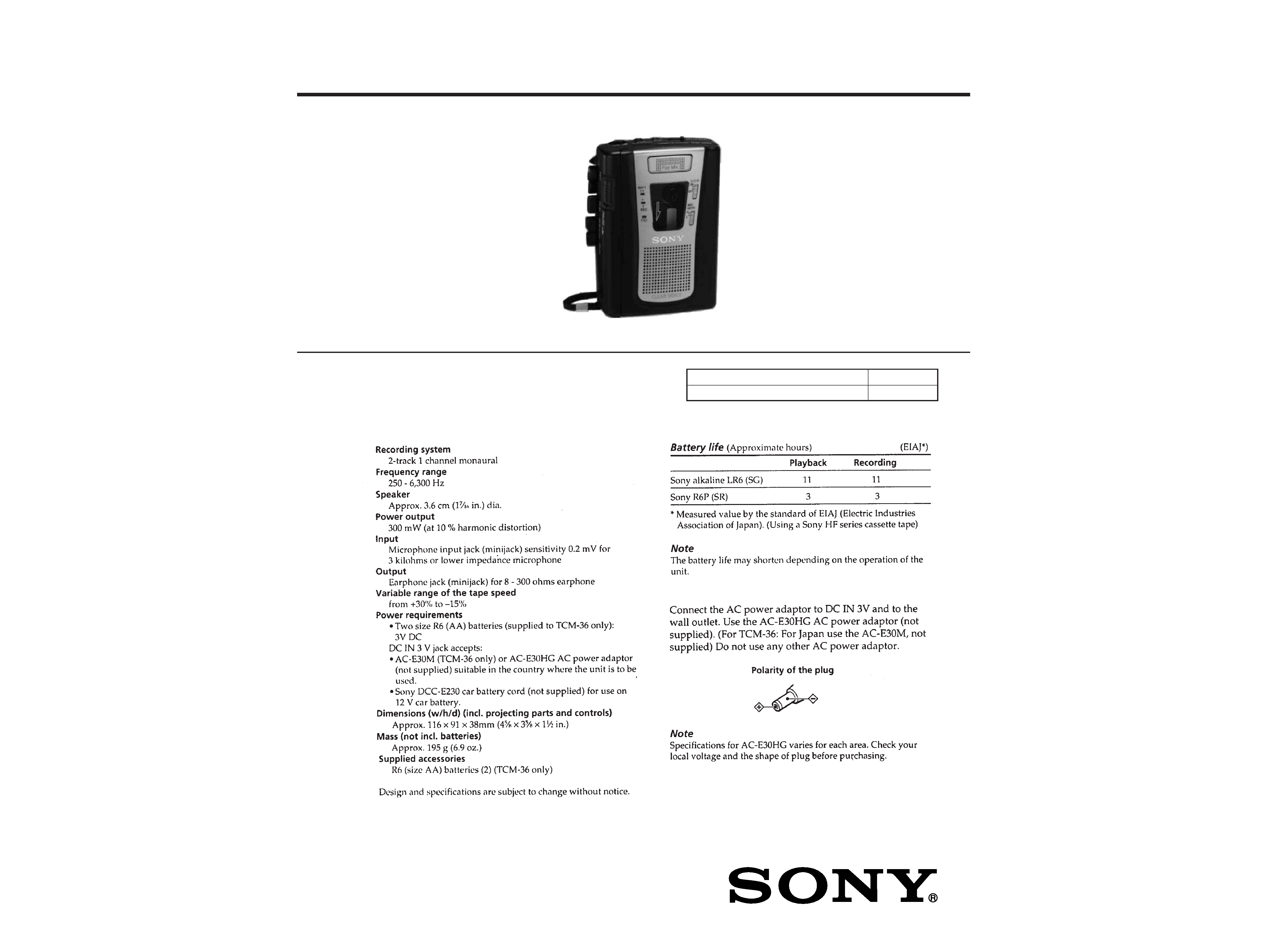
SPECIFICATIONS
TCM-36/459V
Photo: TCM-459V
Ver 1.2 2004.03
9-923-317-12
Sony Corporation
2004C05-1
Personal Audio Company
© 2004.03
Published by Sony Engineering Corporation
2
SECTION 1
GENERAL
TABLE OF CONTENTS
1.
GENERAL ................................................................... 2
2.
DISASSEMBLY ......................................................... 3
3.
MECHANICAL ADJUSTMENTS ....................... 5
4.
ELECTRICAL ADJUSTMENTS ......................... 6
5.
DIAGRAMS
5-1. Block Diagram ................................................................ 7
5-2. Printed Wiring Boards ..................................................... 9
5-3. Schematic Diagram ......................................................... 13
6.
EXPLODED VIEWS ................................................ 16
7.
ELECTRICAL PARTS LIST ............................... 19
Flexible Circuit Board Repairing
· Keep the temperature of the soldering iron around 270 °C dur-
ing repairing.
· Do not touch the soldering iron on the same conductor of the
circuit board (within 3 times).
· Be careful not to apply force on the conductor when soldering
or unsoldering.
Notes on chip component replacement
· Never reuse a disconnected chip component.
· Notice that the minus side of a tantalum capacitor may be dam-
aged by heat.
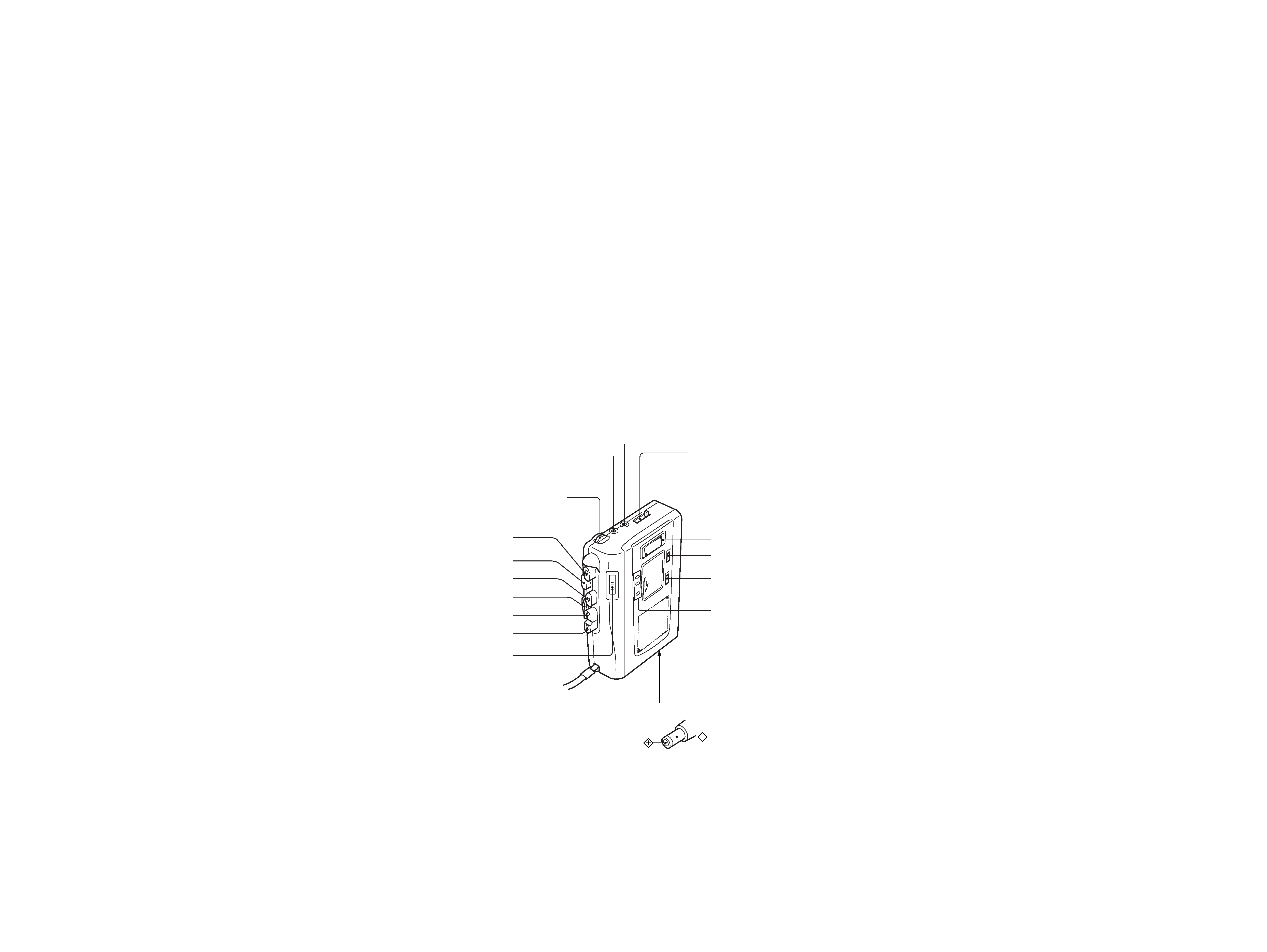
TAPE COUNTER
EAR
MIC
VOL
Flat mic
VOR (TCM-459V)
MIC SENS (TCM-459V)
BATT/REC
r REC
p STOP
( PLAY
0 REW/REVIEW
) FF/CUE
PAUSE c
SPEED CONTROL
DC IN 3V
· Parts Identification
3
SECTION 2
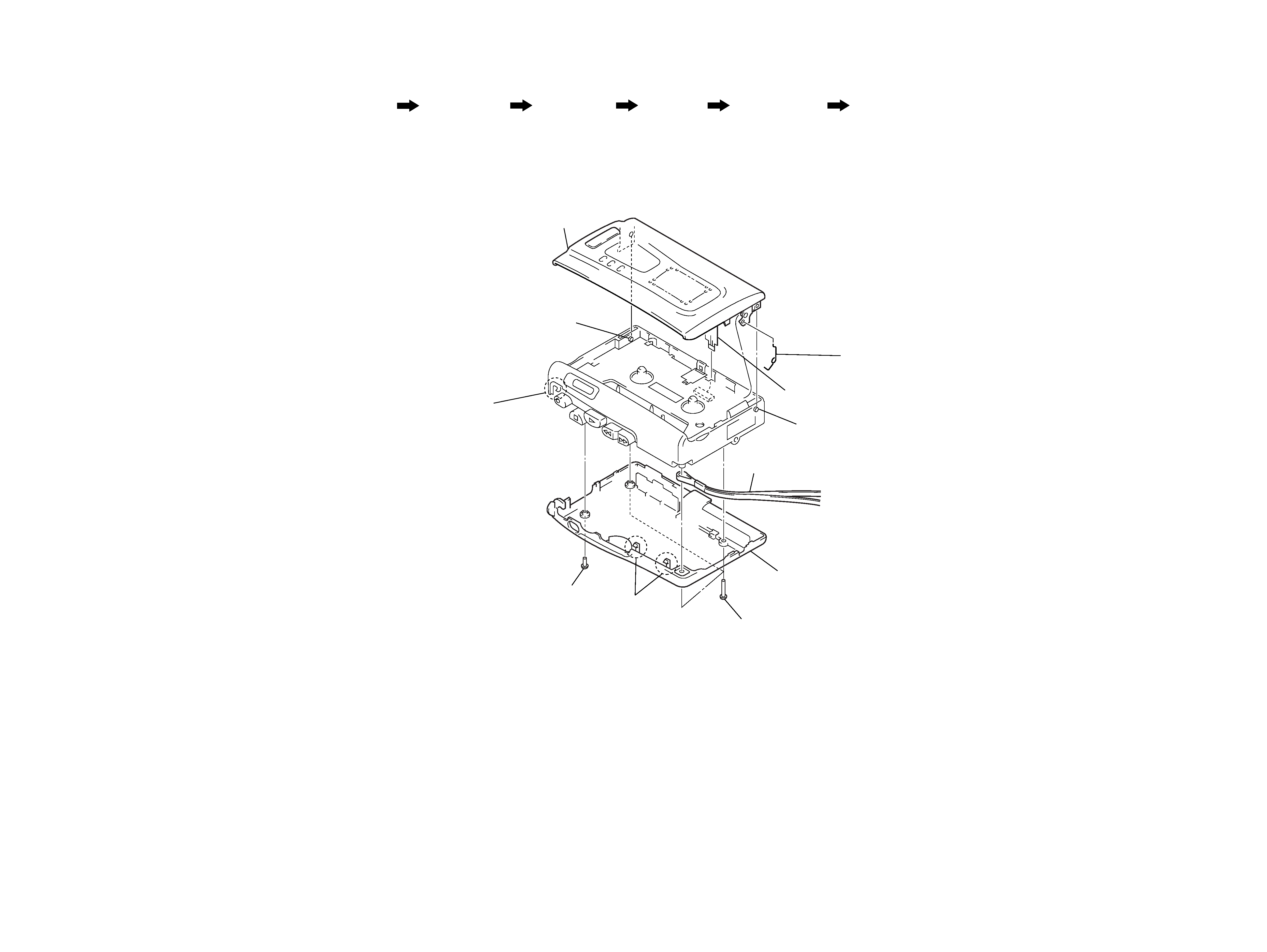
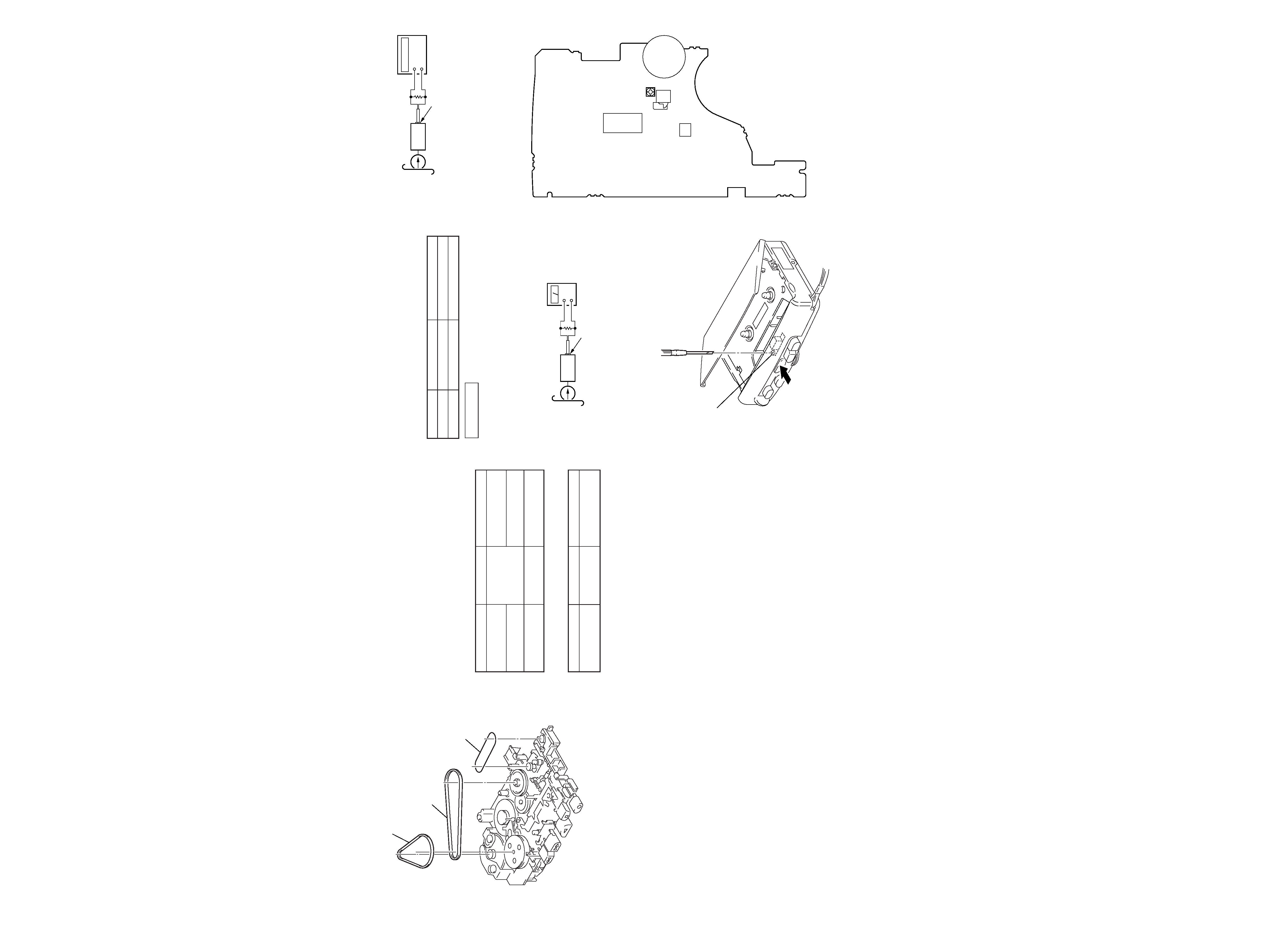
DISASSEMBLY
CABINET (REAR), CASSETTE LID
Note: Follow the disassembly procedure in the numerical order given.
· This set can be disassembled in the order shown below.
SET
CABINET (REAR)
MAIN BOARD
BELT
CASSETTE LID
MECHANISM DECK
(MT-459V-118)
8 cassette lid
5 strap
3 two claws
2 screw
4 cabinet (rear)
1 three screws
(B1.7
× 10)
7 boss
7 boss
9 cassette spring
3claw
6 flexible board
(CN102)
4
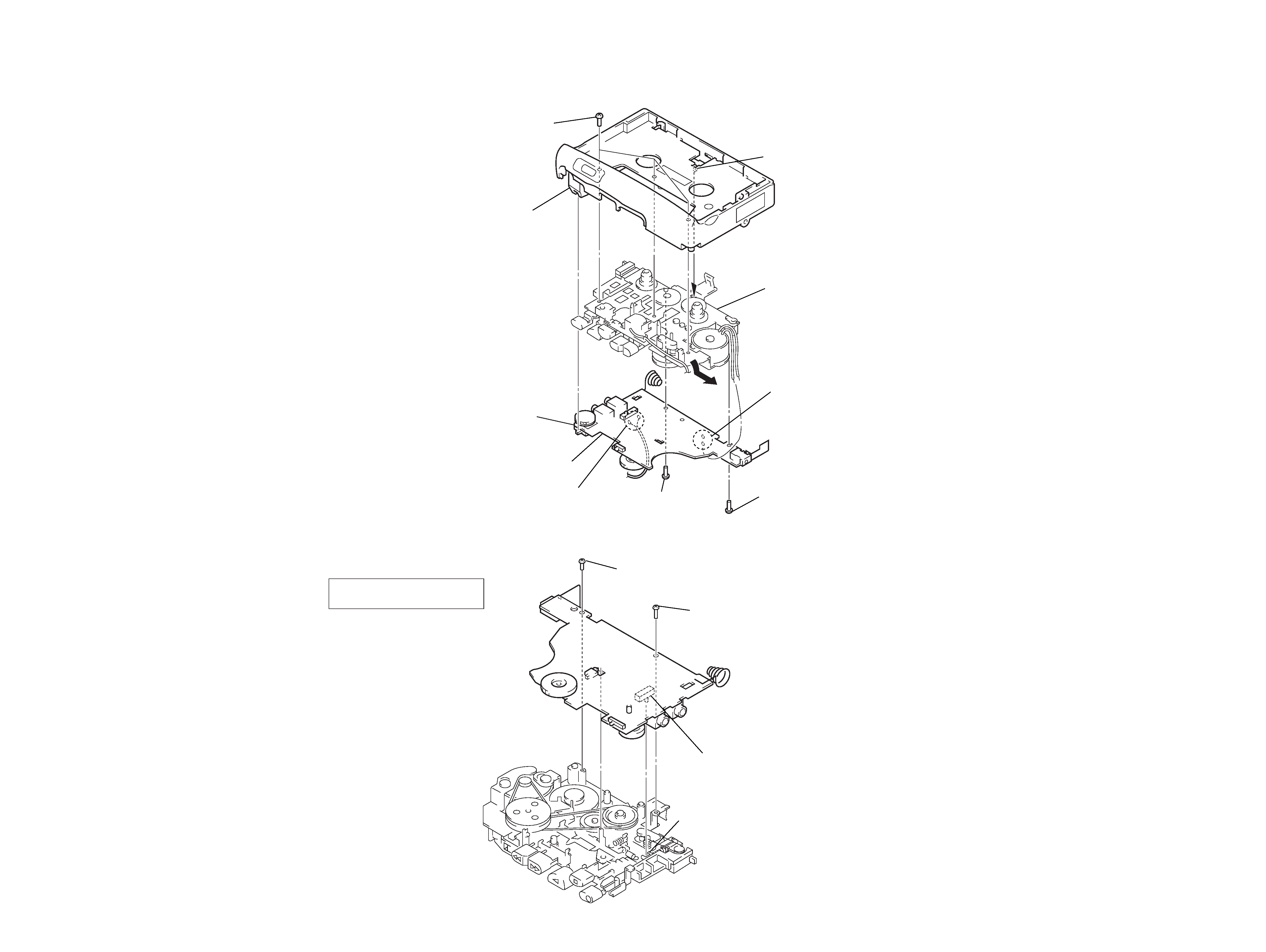
MAIN BOARD, MECHANISM DECK (MT-459V-118)
REC lever
screw
(1.7)
S101
screw
(M1.4)
NOTE FOR INSTALLATION
· MAIN BOARD
On installation MAIN board
adjust the S101 and REC lever.
7 claw
3 screw
(1.7)
4 screw
(M1.4)
5 MAIN board
8 mechanism deck
(MT-459V-118)
6 three screws
(IB lock)
knob (pause)
2 Remove the two solders
of the head lead (HRP901).
1 Remove two solders
of motor leads (M901).
S105
Note: On installation MAIN
board adjust the S105
and knob (pause).
5
6
Precaution
· Supplied voltage: 2.5 V
· Switch and control position
VOR switch (S401): OFF (459V)
PAUSE switch (S105): OFF
VOL (RV101): mechanical mid
SPEED CONTROL (RV602): mechanical center
MIC SENS switch (S201): H (459V)
Test Tape
Record/Playback Head Azimuth Adjustment
Procedure:
Mode: playback
1. Turn the adjustment screw to obtain the maximum reading on
level meter.
Note: Several peaks may appear, but take the maximum.
2. After the adjustment, lock the adjustment screw with suitable
locking compound.
Adjustment Location:
BELT
1 capstan belt
2 FR belt
3 counter belt
SECTION 3
MECHANICAL ADJUSTMENTS
Tape Tension Measurement
1. Clean the following parts with a denatured-alcohol-moistened
swab:
record/playback head
pinch roller
erase head
rubber belt
capstan
idler
2. Demagnetize the record/playback head with a head demagne-
tizer. (Do not bring the head demagnetizer close to the erase
head.)
3. Do not use a magnetized screwdriver for the adjustments.
4. After the adjustments, apply suitable locking compound to the
parts adjusted.
5. The adjustments should be performed with the rated power
supply voltage (2.5 V) unless otherwise noted.
Torque Measurement
Mode
Torque Meter
Meter Reading
FWD
22 48 g·cm
CQ-102C
(0.31 0.67 oz·inch)
Forward Back
1.0 4.5 g·cm
Tension
(0.014 0.063 oz·inch)
FF, REW
CQ-201B
more than 50 g·cm
(more than 0.69 oz·inch)
Mode
Tension Meter
Meter Reading
FWD
CQ-403C
more than 50 g
(more than 1.76 oz)
SECTION 4
ELECTRICAL ADJUSTMENTS
0 dB=0.775 V
Tape Speed Adjustment
Procedure:
Mode: playback
1. Play back WS-48A (tape end part) and adjust RV601 so that
the frequency counter reading becomes 3,000 ± 15 Hz.
2. Play back WS-48A tape the beginning and the end part, check
that the frequency counter reading is within same standard of
step1.
Adjustment Location:
[MAIN BOARD] (Side B)
Type
Signal
Used for
P-4-A063
6.3 kHz, 10 dB
head azimuth adjustment
WS-48A
3 kHz, 0 dB
tape speed adjustment
level meter
test tape
P-4-A063
(6.3 kHz, 10 dB)
10 k
set
EAR jack
+
frequency
counter
Standard tape for adjusting
WS-48A
(3 kHz, 0 dB)
10 k
EAR jack
set
+
adjustment screw
IC101
S102
RV601
RV602
IC501