MICROFILM
SERVICE MANUAL
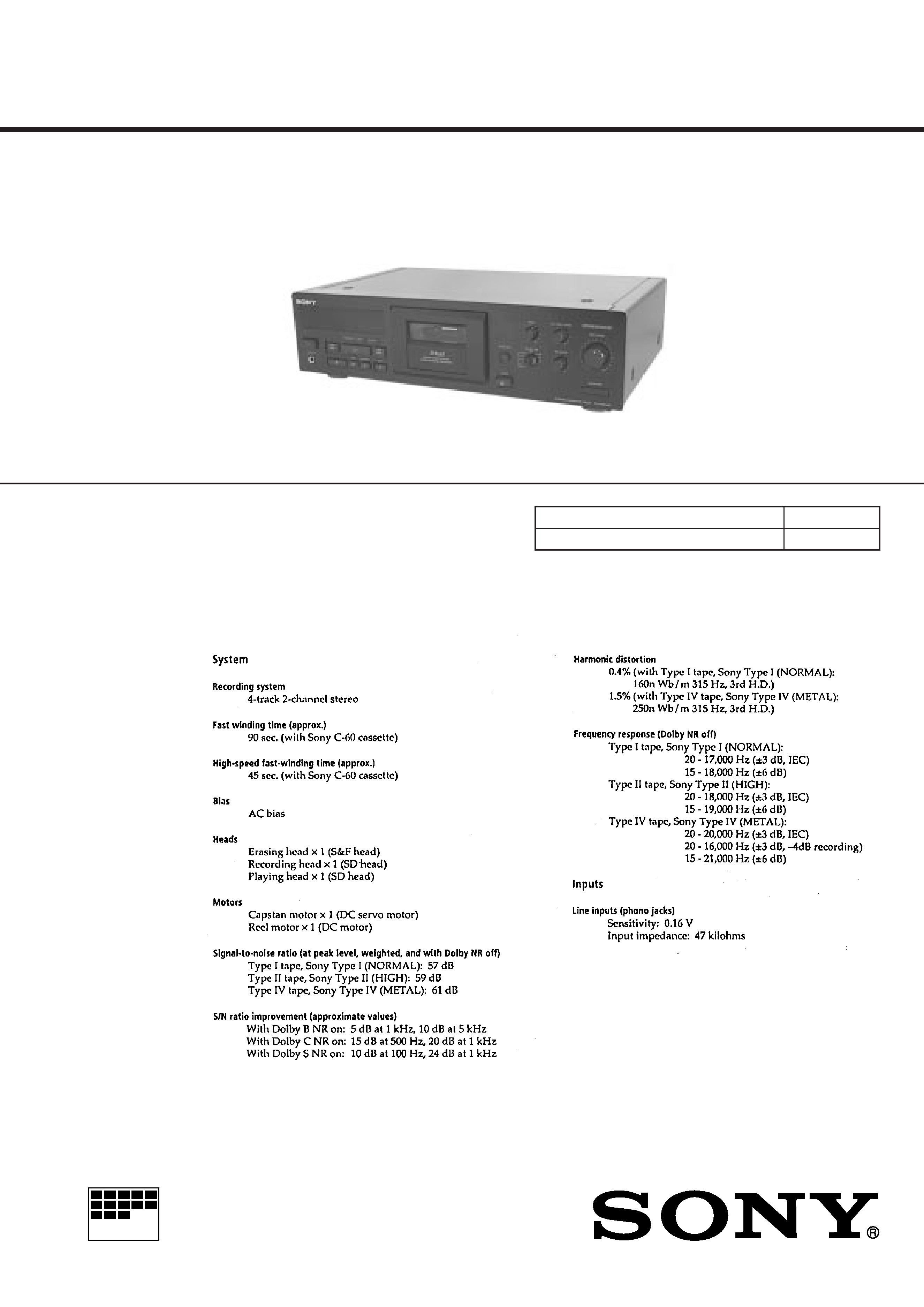
STEREO CASSETTE DECK
AEP Model
E Model
Australian Model
Model Name Using Similar Mechanism
TC-KE500S
Tape Transport Mechanism Type
TCM-190VB14
SPECIFICATIONS
TC-KB920S
Dolby noise reduction and HX Pro headroom ex-
tension manufactured under license from Dolby
Laboratories Licensing Corporation. HX Pro origi-
nated by Bang & Olufsen.
"DOLBY", the double-D symbol
a, and "HX PRO"
are trademarks of Dolby Laboratories Licensing Cor-
poration.
Continued on next page
2
Flexible Circuit Board Repairing
· Keep the temperature of the soldering iron around 270 °C dur-
ing repairing.
· Do not touch the soldering iron on the same conductor of the
circuit board (within 3 times).
· Be careful not to apply force on the conductor when soldering
or unsoldering.
Notes on chip component replacement
· Never reuse a disconnected chip component.
· Notice that the minus side of a tantalum capacitor may be dam-
aged by heat.
SAFETY-RELATED COMPONENT WARNING!!
COMPONENTS IDENTIFIED BY MARK
! OR DOTTED
LINE WITH MARK
! ON THE SCHEMATIC DIAGRAMS
AND IN THE PARTS LIST ARE CRITICAL TO SAFE
OPERATION. REPLACE THESE COMPONENTS WITH
SONY PARTS WHOSE PART NUMBERS APPEAR AS
SHOWN IN THIS MANUAL OR IN SUPPLEMENTS PUB-
LISHED BY SONY.
MODEL IDENTIFICATION
BACK PANEL
3-020-984-
AEP Model
: 0
Australian Model
: 2
Malaysia, Singapore Model: 3

3
TABLE OF CONTENTS
1.
GENERAL ................................................................... 4
2.
DISASSEMBLY ......................................................... 5
3.
MECHANICAL ADJUSTMENTS ....................... 9
4.
ELECTRICAL ADJUSTMENTS ......................... 10
5.
DIAGRAMS
5-1. Note for Printed Wiring Boards and
Schematic Diagrams ....................................................... 14
5-2. Printed Wiring Boards MD Section ......................... 15
5-3. Schematic Diagram MD Section .............................. 17
5-4. Printed Wiring Board MAIN Section ...................... 19
5-5. Schematic Diagram MAIN Section (1/2) ................. 21
5-6. Schematic Diagram MAIN Section (2/2) ................. 23
5-7. Printed Wiring Board DOLBY-S Section ............... 25
5-8. Schematic Diagram DOLBY-S Section .................. 25
5-9. Printed Wiring Boards POWER Section ................. 27
5-10. Schematic Diagram POWER Section ...................... 28
5-11. Printed Wiring Boards PANEL Section .................. 29
5-12. Schematic Diagram PANEL Section ........................ 31
5-13. IC Pin Function Description ........................................... 33
6.
EXPLODED VIEWS ................................................ 35
7.
ELECTRICAL PARTS LIST ............................... 40
4
SECTION 1
GENERAL
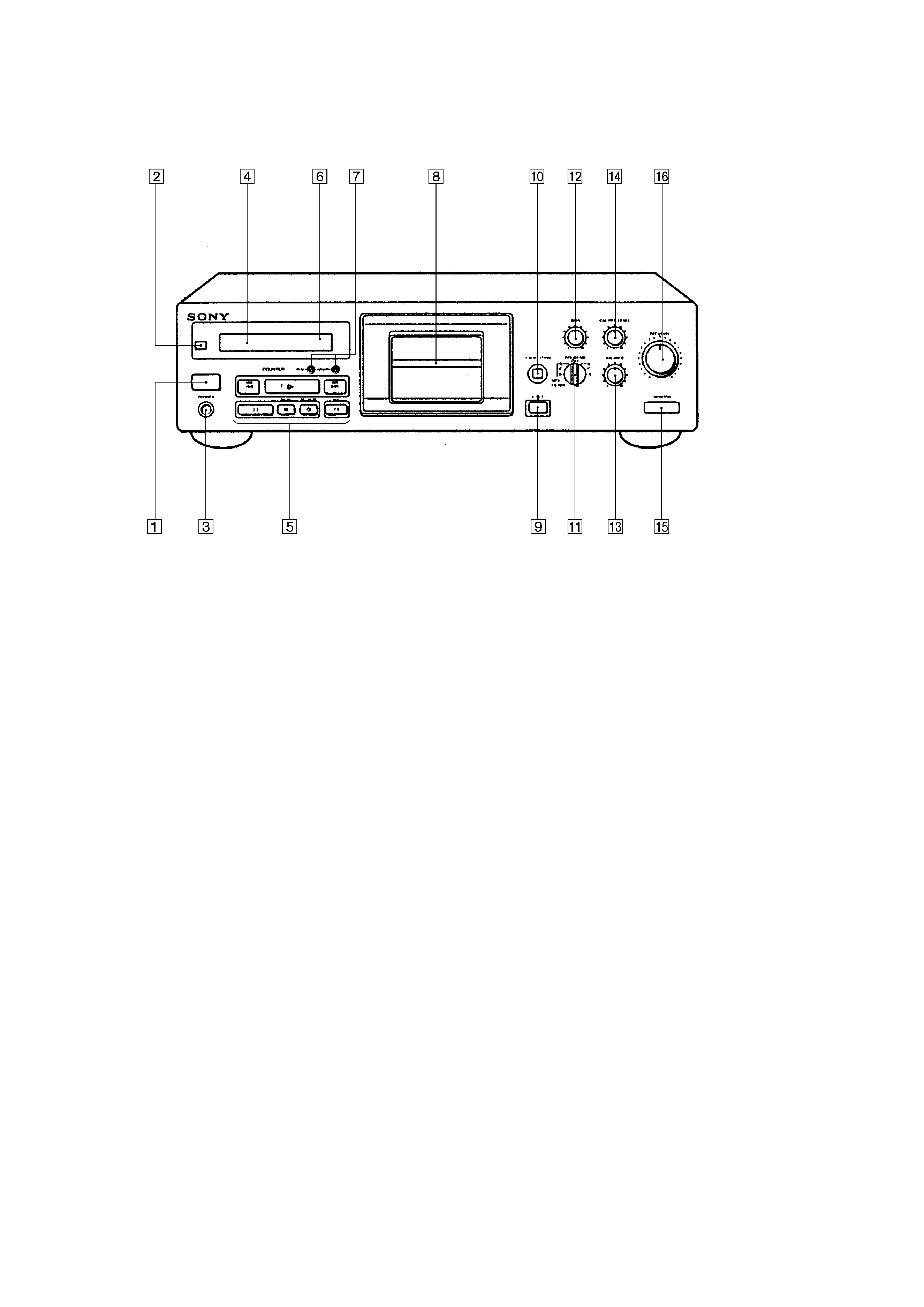
LOCATION OF CONTROLS
1 I/O (Power) button
2 Remote control sensor
3 PHONES jack
4 Display panel
5 Tape operation buttons
AMS*
0 button
· button
AMS*
) button
p button
P PAUSE button
R REC MUTING button
r REC button
6 Tape counter
7 Counter buttons
RESET button
MEMORY button
8 Cassette holder
9 § EJECT button
!º AUTO CAL button
!¡ DOLBY NR switch
!TM BIAS control
!£ BALANCE control
!¢ CAL REC LEVEL control
! MONITOR button
!§ REC LEVEL control
* AMS is an abbreviation for Automatic Music Sensor.
5
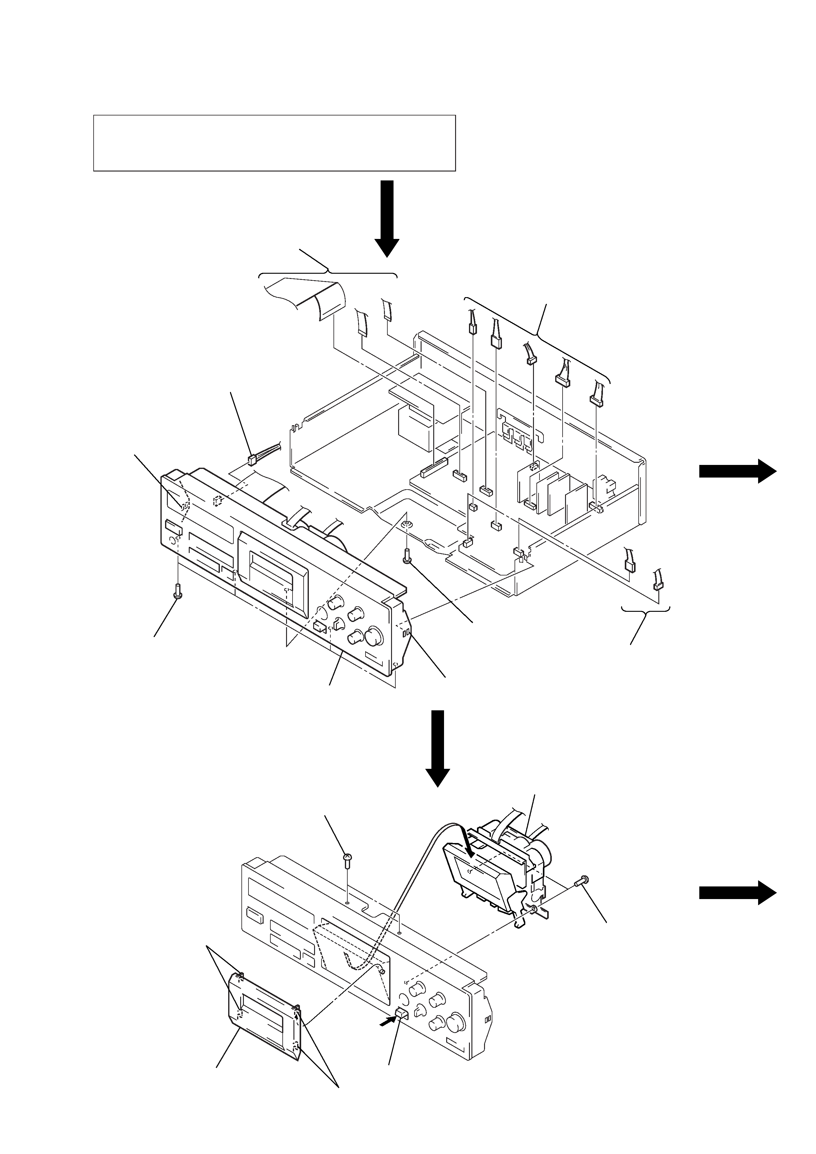
FRONT PANEL SECTION
MD ASS'Y SECTION
Note: Follow the disassembly procedure in the numerical order given.
SECTION 2
DISASSEMBLY
CASE
Unscrew the four case attachment seven tapping screws and
remove the case.
1 three flat cables
(CN803 805)
2 connector
(CN704)
4 claw
4 claw
3 screw
(BVTP3
× 8)
2 two connectors
(CNP304, CN801)
2 five connectors
(CNP301 303, 305, 306)
3 four screws
(BVTP3
× 8)
5 front panel
section
4 two screws
(BVTT2.6
× 8)
5 two screws
(BVTP2.6
× 8)
6 Remove the MD ass'y section
to direction of arrow A.
A
2 two
claws
3 cassette lid
ass'y
2 two claws
1 Push the eject button.