-- 1 --
SERVICE MANUAL
MICROFILM
TA-VE810G
AEP Model
UK Model
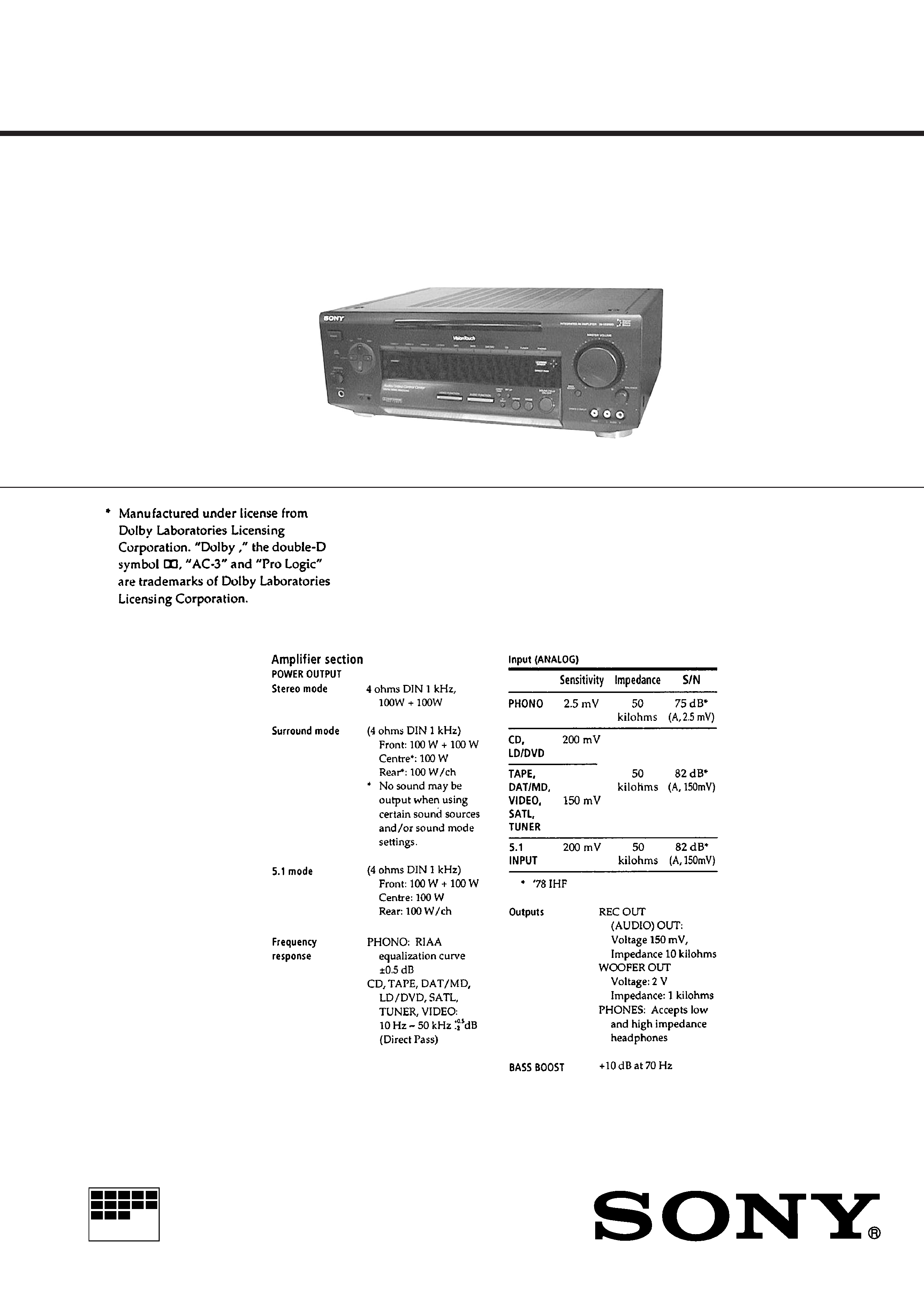
INTEGRATED AV AMPLIFIER
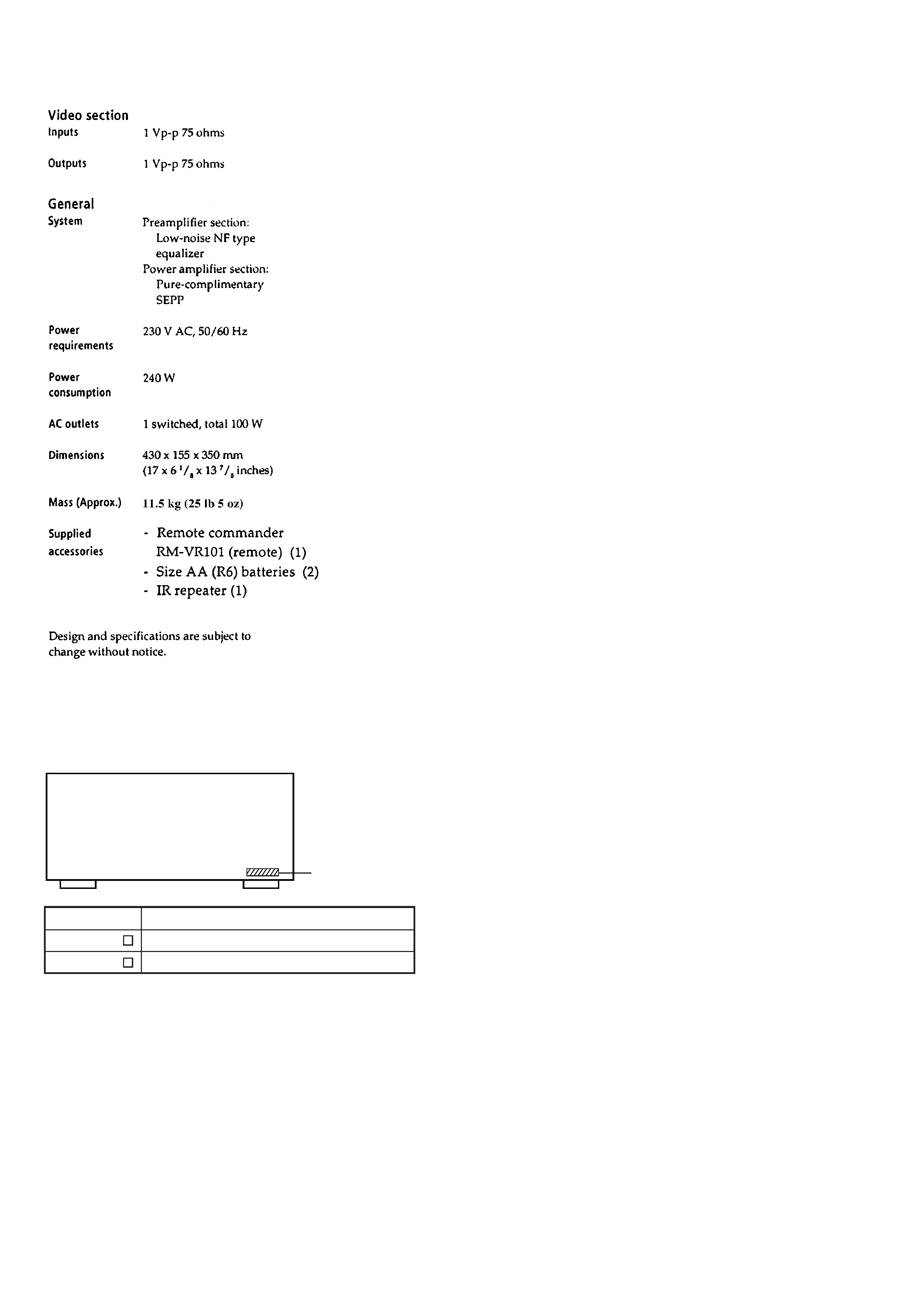
SPECIFICATIONS
-- Continued on next page --
-- 2 --
MODEL IDENTIFICATION
-- BACK PANEL --
Parts No.
Parts No.
Model
4-989-880-5
4-989-880-6
AEP, German, East European model
UK model
TABLE OF CONTENTS
1. SERVICING NOTE .......................................................... 3
2. GENERAL .......................................................................... 4
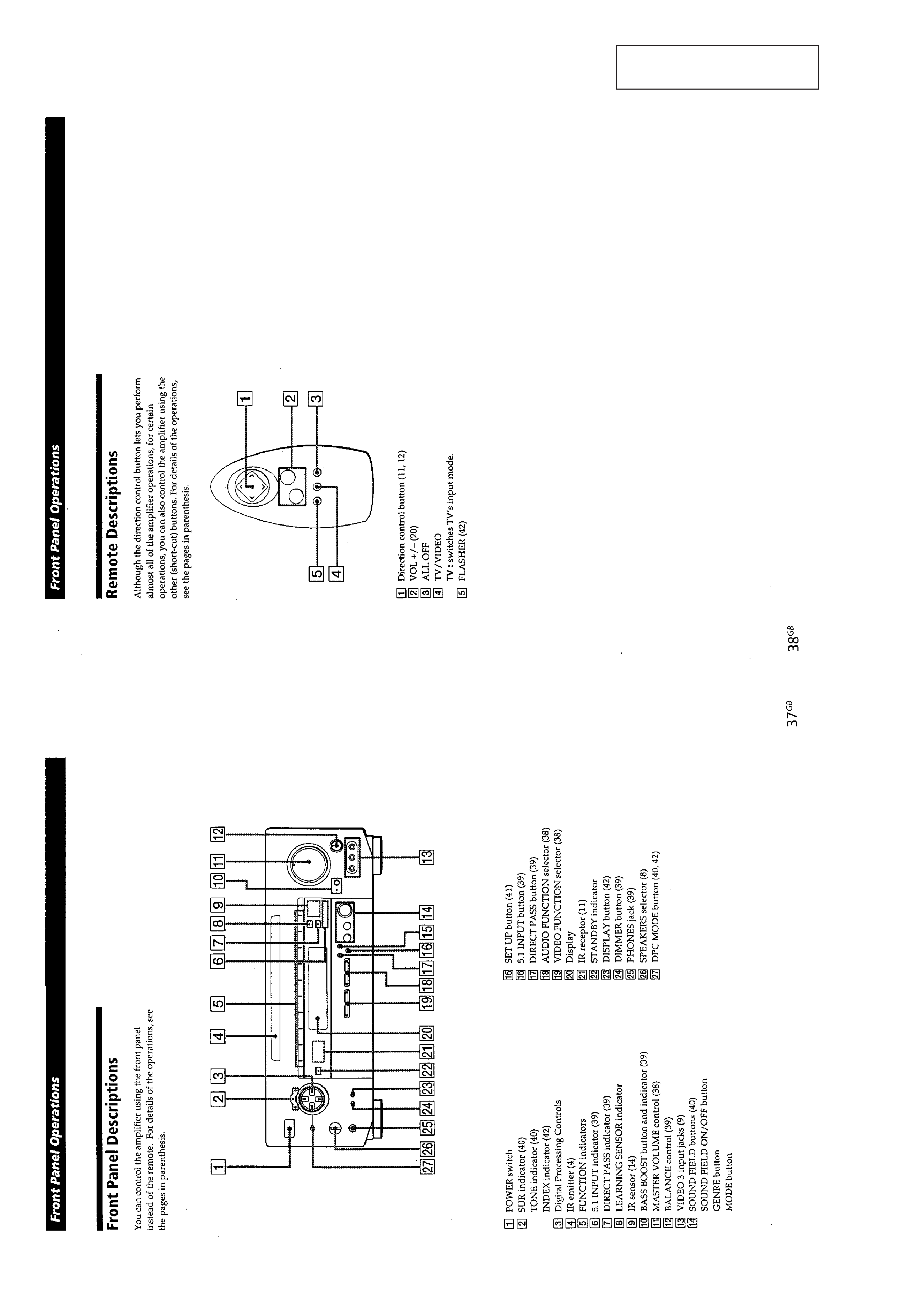
3. DISASSEMBLY
3-1. Front Panel .......................................................................... 22
3-2. Balance Board, Display Board and Volume Board ............. 22
4. ELECTRICAL ADJUSTMENTS ............................... 23
5. DIAGRAMS
5-1. Circuit Boards Location ...................................................... 24
5-2. Printed Wiring Board -- Dolby Surround Section -- ........ 26
5-3. Schematic Diagram -- Dolby Surround Section -- ........... 29
5-4. Schematic Diagram -- OSD Section -- ............................. 33
5-5. Printed Wiring Board -- OSD Section -- .......................... 37
5-6. Printed Wiring Board -- Power Amp Section -- ............... 41
5-7. Schematic Diagram -- Power Amp Section -- .................. 45
5-8. Schematic Diagram -- Panel Section -- ............................ 49
5-9. Printed Wiring Board -- Panel Section -- ......................... 53
5-10. IC Block Diagrams ........................................................... 57
5-11. IC Pin Functions ............................................................... 62
6. EXPLODED VIEWS
6-1. Case Section ........................................................................ 69
6-2. Front panel Section ............................................................. 70
6-3. OSD Board Section ............................................................. 71
6-4. Chassis Section ................................................................... 72
7. ELECTRICAL PARTS LIST ........................................ 73
Notes on chip component replacement
· Never reuse a disconnected chip component.
· Notice that the minus side of a tantalum capacitor may be
damaged by heat.
SAFETY-RELATED COMPONENT WARNING !!
COMPONENTS IDENTIFIED BY MARK
! OR DOTTED LINE
WITH MARK
! ON THE SCHEMATIC DIAGRAMS AND IN
THE PARTS LIST ARE CRITICAL TO SAFE OPERATION.
REPLACE THESE COMPONENTS WITH SONY PARTS
WHOSE PART NUMBERS APPEAR AS SHOWN IN THIS
MANUAL OR IN SUPPLEMENTS PUBLISHED BY SONY.
-- 3 --
ALL CLEAR
Mode which erases all the user memories registered in this unit and
sets to setting at shipment.
Procedure:
1. With the power turned OFF, press the POWER button while
pressing the MODE button, AUDIO FUNCTION > and
VIDEO FUNCTION > button simultaneously to turn ON the
power.
2. ALL CLEAR ! will be displayed on the fluorescent indicator
tube, and ALL CLEAR will be executed.
FACTORY SET
Mode which sets the memory of the unit to the setting of adjust-
ment and check at factory. (Not used for servicing.)
Procedure:
1. With the power turned OFF, press the POWER button while
pressing the MODE button and AUDIO FUNCTION > button
simultaneously to turn ON the power.
2. FACTORY SET will be displayed on the fluorescent indicator
tube, and FACTORY SET will be executed.
Note: In case you return the unit to the customer, do not perform
FACTRY SET. If you do it, perform ALL CLEAR.
Fluorescent indicator tube, LED all lit mode
Procedure:
1. With the power turned OFF, press the POWER button while
pressing the MODE button and VIDEO FUNCTION > button
simultaneously to turn ON the power.
2. The fluorescent display tubes and LEDs will all light up. Re-
lease the buttons in the order of VIDEO FUNCTION > , and
MODE .
3. The Fluorescent indicator tube display changes as follows by
pressing the AUDIO FUNCTION < , AUDIO FUNCTION > .
(Pressing the other buttons will exit this mode.)
SECTION 1
SERVICING NOTE
9
Fluorescent indicator tube and all LEDs are OFF
9
9
Partial lighting of fluorescent indicator tube 2, LEDs are OFF *1
9
Partial lighting of fluorescent indicator tube 1, LEDs are OFF *1
9
Fluorescent indicator tubes, LEDs are all lit
· Press AUDIO FUNCTION < button or AUDIO FUNCTION > button.
· Press AUDIO FUNCTION < button or AUDIO FUNCTION > button.
· Press AUDIO FUNCTION < button or AUDIO FUNCTION > button.
· Press AUDIO FUNCTION < button or AUDIO FUNCTION > button.
*1 Those other than the STANDBY LED go OFF.
4. To exit the mode, press the POWER button to turn OFF the power.
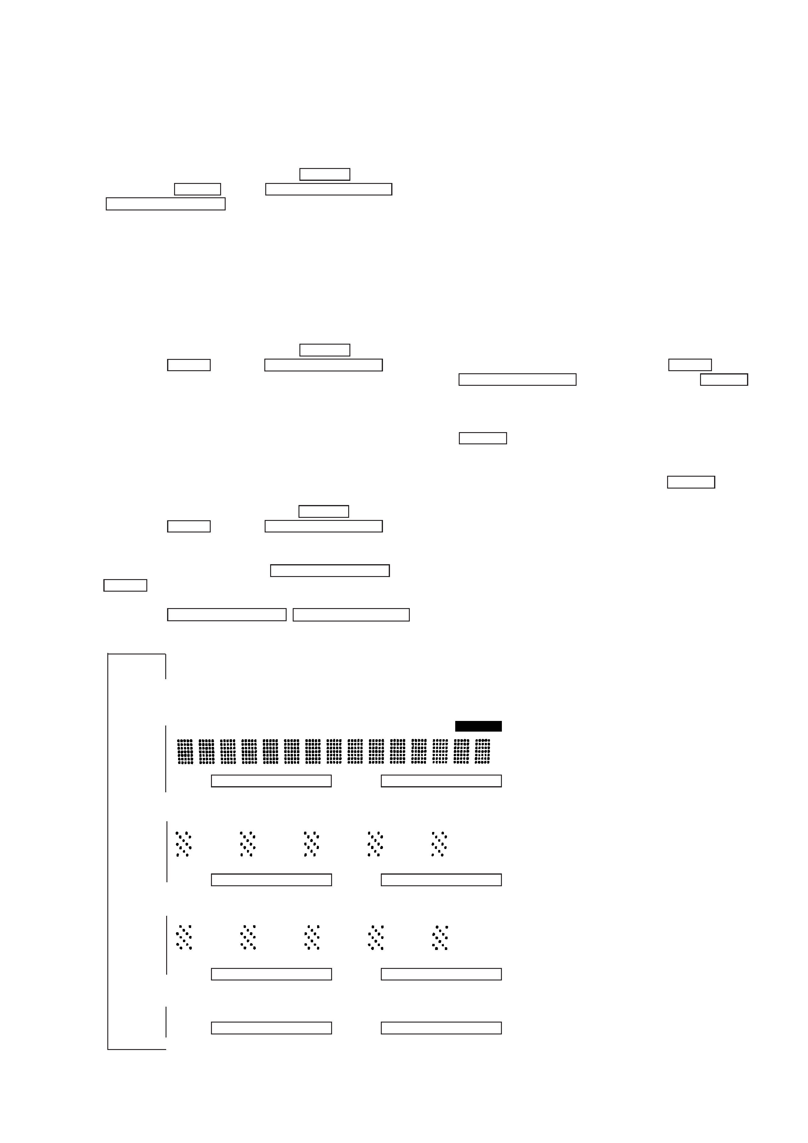
MEMORY
MEMORY
SML THEATER SML HALL ACOUSTIC KARAOKE ARENA STADIUM HIGH
ENHANCED PRO LOGIC MONO MOVIE MUSIC 12 SPORTS GAME STEREO MONO
Adjustment of OSD Screen Position
The position of the screen can be adjusted freely to correct the de-
viation of the OSD screen caused by the monitor type that users are
using.
1. Move the cursor of the remote commander supplied as an acces-
sory, and display the OSD screen.
2. Click the SET UP of the OSD screen.
3. Next click TV SET.
4. Next click GRAPHIC POSITION SET.
5. The screen for adjusting the OSD screen position will be dis-
played. Adjust the position with the remote commander supplied
as an accessory.
6. Click EXIT to end.
Key Check Mode
Method:
1. With the power OFF, while pressing the MODE button and
AUDIO FUNCTION < button together, press the POWER but-
ton.
2. "KEY TEST [18]" will be displayed on the FL display tube.
3. The [XX] number is counted down each time a button other than
POWER is pressed until it becomes [00].
(Buttons pressed once will not be counted again when pressed
another time.)
4. When the number becomes [00], press the POWER button and
exit the mode.
-- 4 --
SECTION 2
GENERAL
This section is extracted from
instruction manual.
-- 5 --