-- 1 --
MICROFILM
AEP Model
UK Model
SERVICE MANUAL
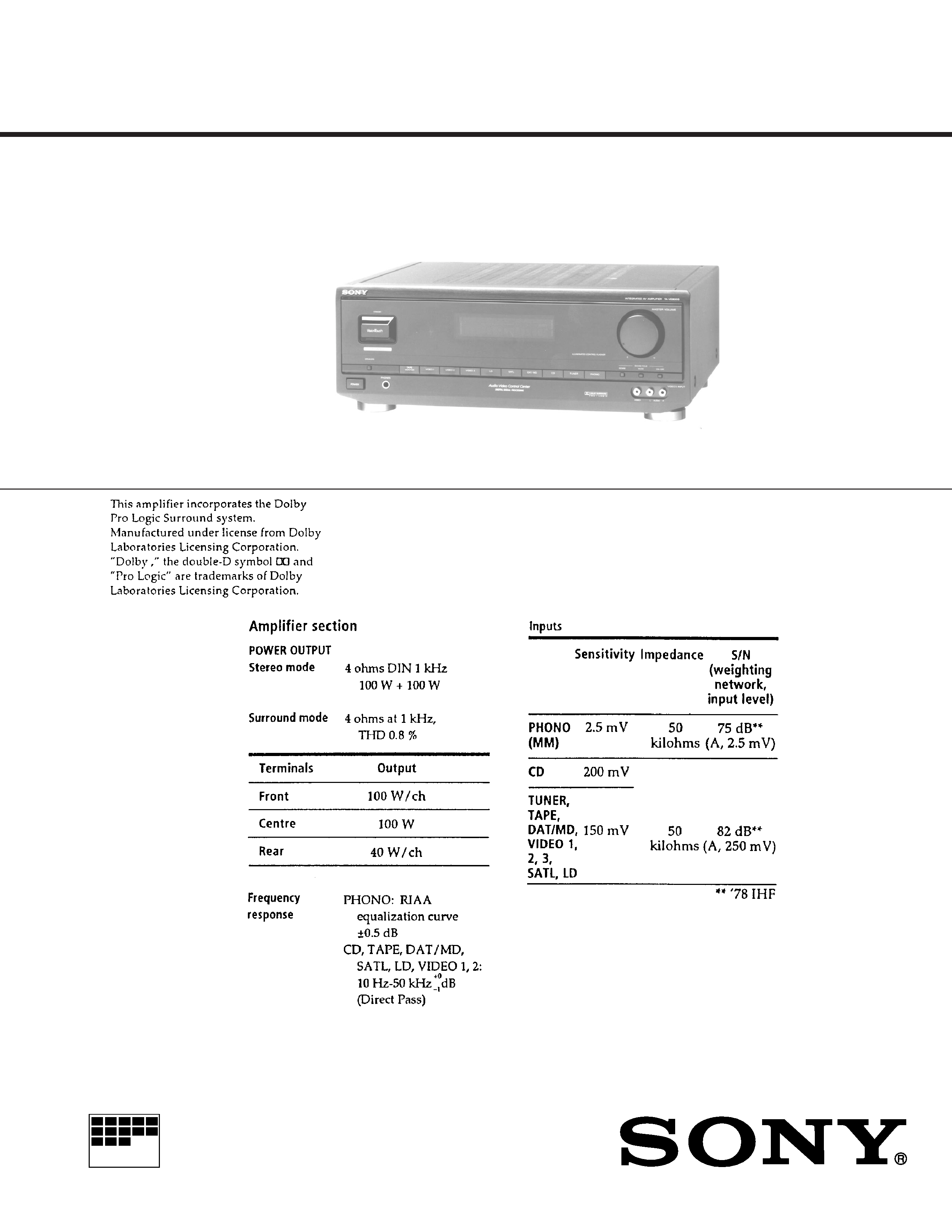
TA-VE800G
SPECIFICATIONS
INTEGRATED AV AMPLIFIER
-- 2 --
TABLE OF CONTENTS
1. SERVICE NOTE ........................................................... 3
2. GENERAL .................................................................... 4
3. DISASSEMBLY .......................................................... 22
4. ELECTRICAL ADJUSTMENT ..................................... 23
5. DIAGRAMS
5-1.
Circuit Boards Location ..................................................... 25
5-2.
Printed Wiring Board -- Surround Section -- ................... 27
5-3.
Schematic Diagram -- Surround Section -- ..................... 31
5-4.
Schematic Diagram -- OSD Section -- ............................ 35
5-5.
Printed Wiring Board -- OSD Section -- .......................... 39
5-6.
Printed Wiring Board -- Amp Section -- .......................... 43
5-7.
Schematic Diagram -- Amp Section -- ............................. 47
5-8.
Schematic Diagram -- Display Section -- ........................ 50
5-9.
Printed Wiring Board -- Display Section -- ..................... 53
5-10. IC Block Diagrams
-- Surround Section -- ...................................................... 57
-- OSD Section -- ............................................................. 59
-- Amp Section -- ............................................................. 60
-- Display Section -- ......................................................... 61
5-11. IC Pin Function
· IC107 Display control
(MB90673PF-G-166-BND) ............................................ 62
· IC205 OSD
(MB90095PF-G-161-BND) ............................................ 64
· IC209 OSD Controller
(MB90672PF-G-125-BND) ............................................ 65
· IC215 RC Controller
(S-1810CF-049) .............................................................. 67
6. EXPLODED VIEWS
6-1.
Case and Front Panel Section ............................................. 68
6-2.
Back Panel Section ............................................................. 69
6-3.
Chassis Section ................................................................... 70
7. ELECTRICAL PARTS LIST ..................................... 71
SAFETY-RELATED COMPONENT WARNING !!
COMPONENTS IDENTIFIED BY MARK
! OR DOTTED LINE
WITH MARK
! ON THE SCHEMATIC DIAGRAMS AND IN
THE PARTS LIST ARE CRITICAL TO SAFE OPERATION.
REPLACE THESE COMPONENTS WITH SONY PARTS
WHOSE PART NUMBERS APPEAR AS SHOWN IN THIS
MANUAL OR IN SUPPLEMENTS PUBLISHED BY SONY.
Notes on chip component replacement
· Never reuse a disconnected chip component.
· Notice that the minus side of a tantalum capacitor may be
damaged by heat.

-- 3 --
SECTION 1
SERVICE NOTE
ALL CLEAR
Mode which erases all the user memories registered in this unit and
sets to setting at shipment.
Method:
1. With the power turned OFF, press the POWER button while press-
ing the TAPE MONITOR button and VIDEO 2 button simulta-
neously to turn ON the power.
2. ALL CLEAR ! will be displayed on the fluorescent indicator tube,
and ALL CLEAR will be executed.
FACTORY SET
Mode which sets the memory of the unit to the setting of adjustment
and check at factory. (Not used for servicing.)
Method:
1. With the power turned OFF, press the POWER button while press-
ing the SPEAKER button and TAPE button simultaneously to turn
ON the power.
2. FACTORY SET will be displayed on the fluorescent indicator
tube, and FACTORY SET will be executed.
Note: In case you return the unit to the customer, do not perform
FACTRY SET. If you do it, perform ALL CLEAR.
Fluorescent indicator tube, LED all lit mode and key check
mode
Method:
1. With the power turned OFF, press the POWER button while press-
ing the TAPE MONITOR button, VIDEO 1 button, and VIDEO 2
button simultaneously to turn ON the power.
2. The fluorescent display tubes and LEDs will all light up.
3. The display will change as follows each time buttons other than
GENRE and MODE are pressed. Therefore, it can be checked if
buttons have been input properly by whether the display changes.
Adjustment of OSD Screen Position
The position of the screen can be adjusted freely to correct the devia-
tion of the OSD screen caused by the monitor type that users are
using.
1. Move the cursor of the remote commander attached, and display
the OSD screen.
2. Click the MAIN MENU FUNCTION of the OSD screen.
3. Next click TV SET.
4. Next click GRAPHIC POSITION SET.
5. The screen for adjusting the OSD screen position will be displayed.
Adjust the position with the remote commander attached.
6. Click EXIT to end.
*1 Those other than the POWER LED go OFF.
4. To exit the mode, press the POWER button to turn OFF the
power.
Fluorescent indicator tubes, LEDs are all lit
Press any button
Partial lighting of fluorescent indicator tube 1, LEDs are OFF *1
Press any button
Partial lighting of fluorescent indicator tube 2, LEDs are OFF *1
Press any button
Press any button
Fluorescent indicator tube and all LEDs are OFF *1
N
N
N
N
NNN
N
N
-- 4 --
SECTION 2
GENERAL
This section is extracted from
instruction manual.
-- 5 --