SERVICE MANUAL
A/V AMPLIFIER
AEP Model
UK Model
E Model
Australian Model
SPECIFICATIONS
TA-S9D
Ver 1.0 2001.09
9-873-282-01
Sony Corporation
2001I0500-1
Home Audio Company
C
2001.9
Shinagawa Tec Service Manual Production Group
TA-S9D is the Amplifier section
in MHC-S9D.
Amplifier section
European model:
Front Speaker:
DIN power output (rated) 95 + 95 watts
(6 ohms at 1 kHz, DIN)
Continuous RMS power output (reference)
120 + 120 watts
(6 ohms at 1 kHz, 10%
THD)
Music power output (reference)
200 + 200 watts
(6 ohms at 1 kHz, 10%
THD)
Center Speaker:
DIN power output (rated) 30 watts
(8 ohms at 1 kHz, DIN)
Continuous RMS power output (reference)
40 watts
(8 ohms at 1 kHz, 10%
THD)
Music power output (reference)
75 watts
(8 ohms at 1 kHz, 10%
THD)
Rear Speaker:
DIN power output (rated) 30 + 30 watts
(8 ohms at 1 kHz, DIN)
Continuous RMS power output (reference)
40 + 40 watts
(8 ohms at 1 kHz, 10%
THD)
Music power output (reference)
75 + 75 watts
(8 ohms at 1 kHz, 10%
THD)
Other models:
The following measured at AC 120, 220, 240 V,
50/60 Hz
Front Speaker:
DIN power output (rated) 95 + 95 watts
(6 ohms at 1 kHz, DIN)
Continuous RMS power output (reference)
40 watts
(8 ohms at 1 kHz, 10%
THD)
Center Speaker:
DIN power output (rated) 30 watts
(8 ohms at 1 kHz, DIN)
General
Power requirements
European model:
230 V AC, 50/60 Hz
Australian model:
230 240 V AC,
50/60 Hz
Mexican model:
120 V AC, 60 Hz
Korean model:
220 V AC, 60 Hz
Thailand model:
220 V AC, 50/60 Hz
Other models:
120 V, 220 V or
230 240 V AC,
50/60 Hz
Adjustable with voltage
selector
Power consumption
European model:
300 watts
0.6 watts (at the Power
Saving Mode)
Other models:
300 watts
Dimensions (w/h/d)
Approx. 280 x 128 x 350 mm
Mass
Approx. 7.7 kg
Design and specifications are subject to change
without notice.
Continuous RMS power output (reference)
120 + 120 watts
(6 ohms at 1 kHz, 10%
THD)
REAR SPEAKER:
accepts impedance of 8 to
16 ohms
CENTER SPEAKER:
accepts impedance of 8 to
16 ohms
SUB WOOFER OUT:
Voltage 1 V,
impedance 1 kilohms
Rear Speaker:
DIN power output (rated) 30 + 30 watts
(8 ohms at 1 kHz, DIN)
Continuous RMS power output (reference)
40 + 40 watts
(8 ohms at 1 kHz, 10%
THD)
Inputs
VIDEO (AUDIO) IN:
voltage 250 mV,
(phono jacks)
impedance 47 kilohms
MD IN:
voltage 450 mV,
(phono jacks)
impedance 47 kilohms
OPTICAL IN:
(Square optical connector jacks, rear panel)
MIC:
sensitivity 1 mV,
(Except for North
impedance 10 kilohms
American and
European models)
(phone jack)
Outputs
MD OUT:
voltage 250 mV
(phono jacks)
impedance 1 kilohms
VIDEO OUT:
max. output level
(phono jack)
1 Vp-p, unbalanced, Sync
negative, load impedance
75 ohms
S-VIDEO OUT:
Y: 1 Vp-p, unbalanced,
(4-pin/mini-DIN jack)
Sync negative,
C: 0.286Vp-p,
load impedance 75 ohms
PHONES:
accepts headphones of
(stereo mini jack)
8 ohms or more
FRONT SPEAKER:
accepts impedance of 6 to
16 ohms

2
TA-S9D
TABLE OF CONTENTS
1.
SERVICING NOTES ............................................... 3
2.
GENERAL ................................................................... 4
3.
DISASSEMBLY
3-1. Disassembly Flow ...........................................................
5
3-2. Case .................................................................................
6
3-3. Front Panel Section .........................................................
6
3-4. Back Panel (DVD) Section .............................................
7
3-5. FRONT AMP Board .......................................................
7
4.
TEST MODE .............................................................. 8
5.
DIAGRAMS
5-1. Note for Printed Wiring Boards
and Schematic Diagrams ................................................ 10
5-2. Printed Wiring Boards FRONT AMP Section ........ 11
5-3. Schematic Diagram FRONT AMP Section (1/2) .... 12
5-4. Schematic Diagram FRONT AMP Section (2/2) .... 13
5-5. IC Pin Function Description ........................................... 14
5-6. Printed Wiring Board
SURROUND AMP Section ...................................... 14
5-7. Schematic Diagram
SURROUND AMP Section ...................................... 15
5-8. Printed Wiring Boards CONTROL Section ............ 16
5-9. Schematic Diagram CONTROL Section ................. 17
5-10. Printed Wiring Boards POWER Section ................. 18
5-11. Schematic Diagram POWER Section ..................... 19
6.
EXPLODED VIEWS
6-1. Case Section .................................................................... 20
6-2. Front Panel Section ......................................................... 20
6-3. Chassis Section ............................................................... 21
7.
ELECTRICAL PARTS LIST ............................... 22
SAFETY-RELATED COMPONENT WARNING!!
COMPONENTS IDENTIFIED BY MARK 0 OR DOTTED
LINE WITH MARK 0 ON THE SCHEMATIC DIAGRAMS
AND IN THE PARTS LIST ARE CRITICAL TO SAFE
OPERATION. REPLACE THESE COMPONENTS WITH
SONY PARTS WHOSE PART NUMBERS APPEAR AS
SHOWN IN THIS MANUAL OR IN SUPPLEMENTS PUB-
LISHED BY SONY.
3
TA-S9D
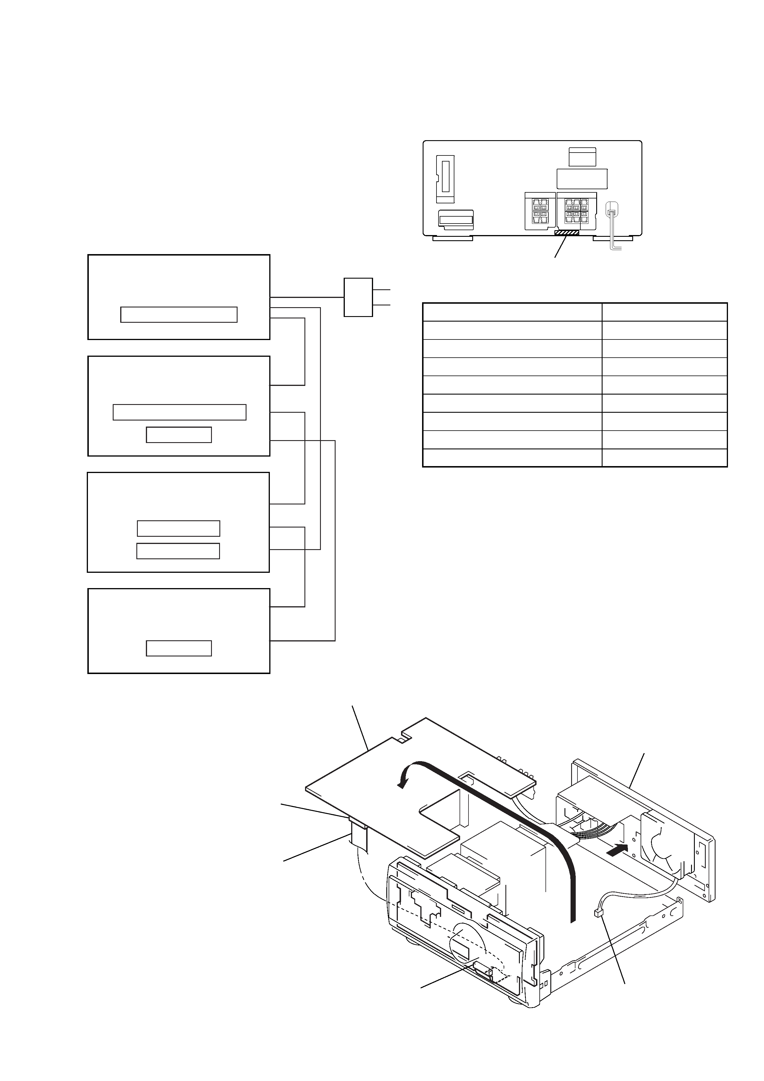
FRONT AMP BOARD SERVICE POSITION
In checking the FRONT AMP board, prepare jig
(extension cable J-2501-019-A: 1.25 mm Pitch, 25 core, Length
300 mm) (except AEP, UK models)
(extension cable J-2501-087-A: 1.25 mm Pitch, 23 core, Length
300 mm) (AEP, UK models)
(Fig A)
SECTION 1
SERVICING NOTES
This set is a component of the MHC-S9D.
The MHC-S9D system configuration is as shown below, and there-
fore it does not operate normally unless all four components are
connected.
In performing the repair, connect all components with the system
cables.
Note: The precaution to the users is described on the label stuck
on the back panel (DVD/video CD/CD player) and in the trouble-
shooting section in the Operation Manual.
System Configuration:
POWER SUPPLY
AC IN
TA
MASTER & GRAPHIC
µcon
ST
TC
µcon
TC
DISPLAY
HTC & MB
µcon
DVP
POWER BLOCK
MODEL IDENTIFICATION
Back Panel
Turn over the FRONT AMP board with Heat Sink,
SURROUND AMP board and RELAY board connected.
Remove the back panel
(AV) section.
Remove the fan motor
connector lead wire.
FRONT AMP board
(CN104)
Connect jig (extension cable
J-2501-019-A (except AEP, UK models),
J-2501-087-A (AEP, UK models)
to the FRONT AMP board (CN104)
and PANEL board (CN700).
PANEL board (CN700)
(Fig A)
PART No.
Model
PART No.
AEP, UK models
4-232-348-0[]
Singapore model
4-232-348-4[]
Saudi Arabia model
4-232-348-5[]
Australian model
4-232-348-6[]
Thai model
4-232-348-7[]
E model
4-232-348-8[]
Mexican model
4-232-348-9[]
Korean model
4-233-563-0[]
4
TA-S9D
SECTION 2
GENERAL
This section is extracted from
instruction manual.
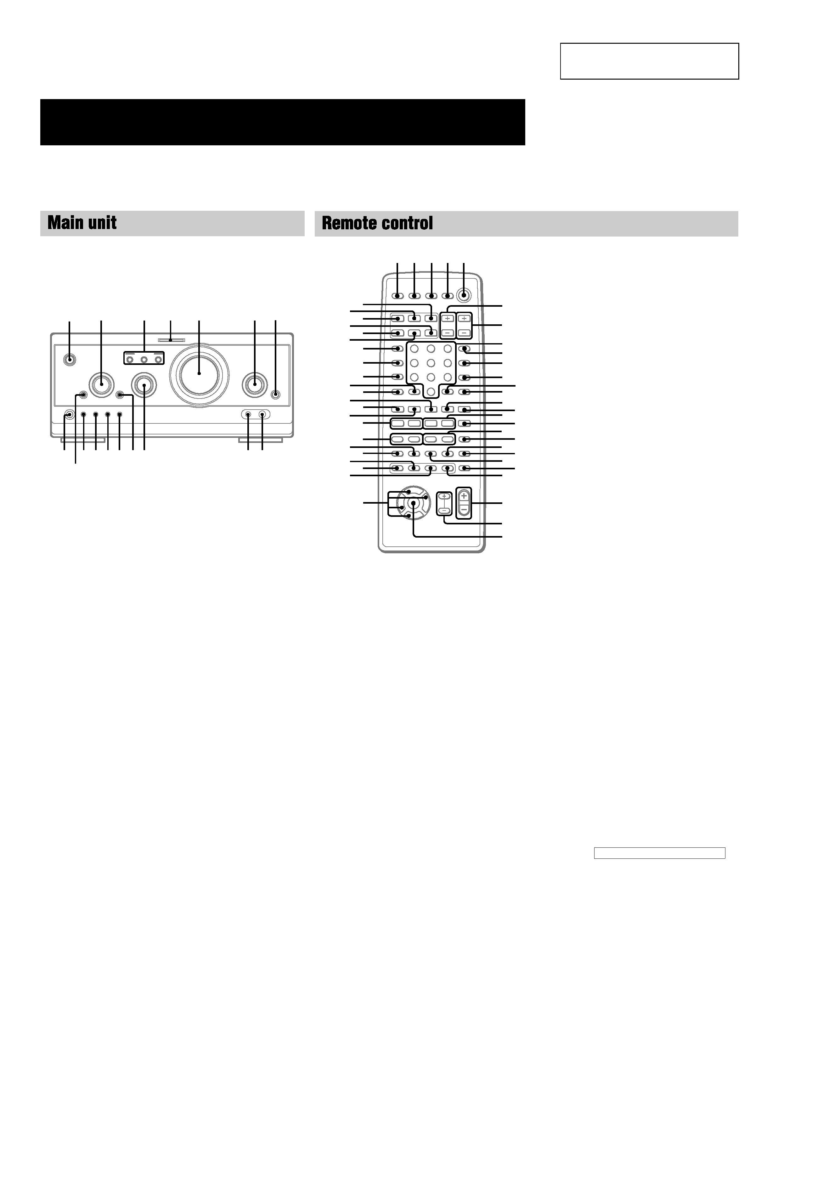
Parts Identification
The items are arranged in alphabetical order.
Refer to the pages indicated in parentheses ( ) for details.
A/V amplifier
CINEMA STUDIO AC 3 (49)
DIGITAL 7 (57, 63)
DVD MENU qf (27)
ENTER/O/o/P/p 2
EQ qa (52)
EQ ON/OFF qs (13, 53)
FILE SELECT q; (26, 48, 49,
53)
FUNCTION 6 (12, 13, 25, 27,
28, 36, 45, 46, 55, 57, 62)
MIC jack (Except for European
model) 9 (54)
MIC LEVEL (Except for European
model) 8 (54)
MULTI CHANNEL DECODING
indicator 4 (50)
PHONES jack qj
SET UP qd (14, 16, 51, 53, 54)
SUR qh (51)
TITLE qg (27)
VOLUME 5
@/1
(power) 1 (12, 13, 63)
A
P
o
O
p
B
C
4
3
5
6
2
7
8
9
q;
qa
qs
qd
qf
qg
qh
qj
1
ANGLE es (37)
AUDIO ws (34)
CLEAR qs (22, 29, 30, 36)
CLOCK/TIMER SELECT 3
(47, 56)
CLOCK/TIMER SET 2 (17, 47,
56)
DBFB ra (48)
D.SKIP 9 (26)
DIGITAL rf (57)
DISPLAY rj (17, 31, 32, 43, 54)
DVD DISPLAY wd (18, 19, 30,
3234, 3640)
DVD MENU wa (27)
DVD SET UP ql (18, 19, 24, 39)
ENTER wj
EQ ea (52)
EQ ON/OFF wl (53)
FILE SELECT +/ wh (48, 49,
53)
FUNCTION rd (18, 25, 27, 28,
36, 45, 46, 55, 57)
GROOVE rs (48)
KARAOKE PON (Except for
European model) el (54)
MD rh (57)
Numeric buttons 8 (28, 30)
PLAY MODE qa (25, 28, 29, 46)
REPEAT q; (30)
RETURN O qd (27, 39, 40)
SELECT DVD N eh (20, 25,
27, 29, 30)
SET UP wf (14, 16, 51, 53, 54)
SLEEP 1 (55)
SLOW t/T qk (26)
SPECTRUM ANALYZER rk
(54)
STEP c/C ef (26)
SUBTITLE ed (37)
SUR e; (51)
TAPE A nN ek (44)
TAPE B nN qf (44, 45)
TITLE w; (27)
TUNER/BAND ej (42)
TV @/1 4 (13)
TV CH +/ 7 (13)
TV/VIDEO rl (13)
TV VOL +/ 6 (13)
VIDEO rg (57)
VOL +/ wg
x
M
m
>
.
nN
O
X
T
t
C
c
V
v
Bb
12
3
4 5
e;
es
ef
ej
eg
6
7
9
8
q;
qa
qd
qs
qf
qg
qj
qh
qk
ql
wa
wd
ws
wf
w;
wg
wj
wh
wk
ed
wl
ea
eh
el
rs
ra
rd
ek
r;
rg
rj
rl
rf
rh
rk
BUTTON DESCRIPTIONS
@/1
(power) 5
X
(pause) qj
x
(stop) qg
m/M
(rewind/fast forward),
TUNING /+ qh
./>
(go back/go forward),
PRESET /+, PREV/NEXT
eg
O/o/P/p wk
>10 r;
5
TA-S9D
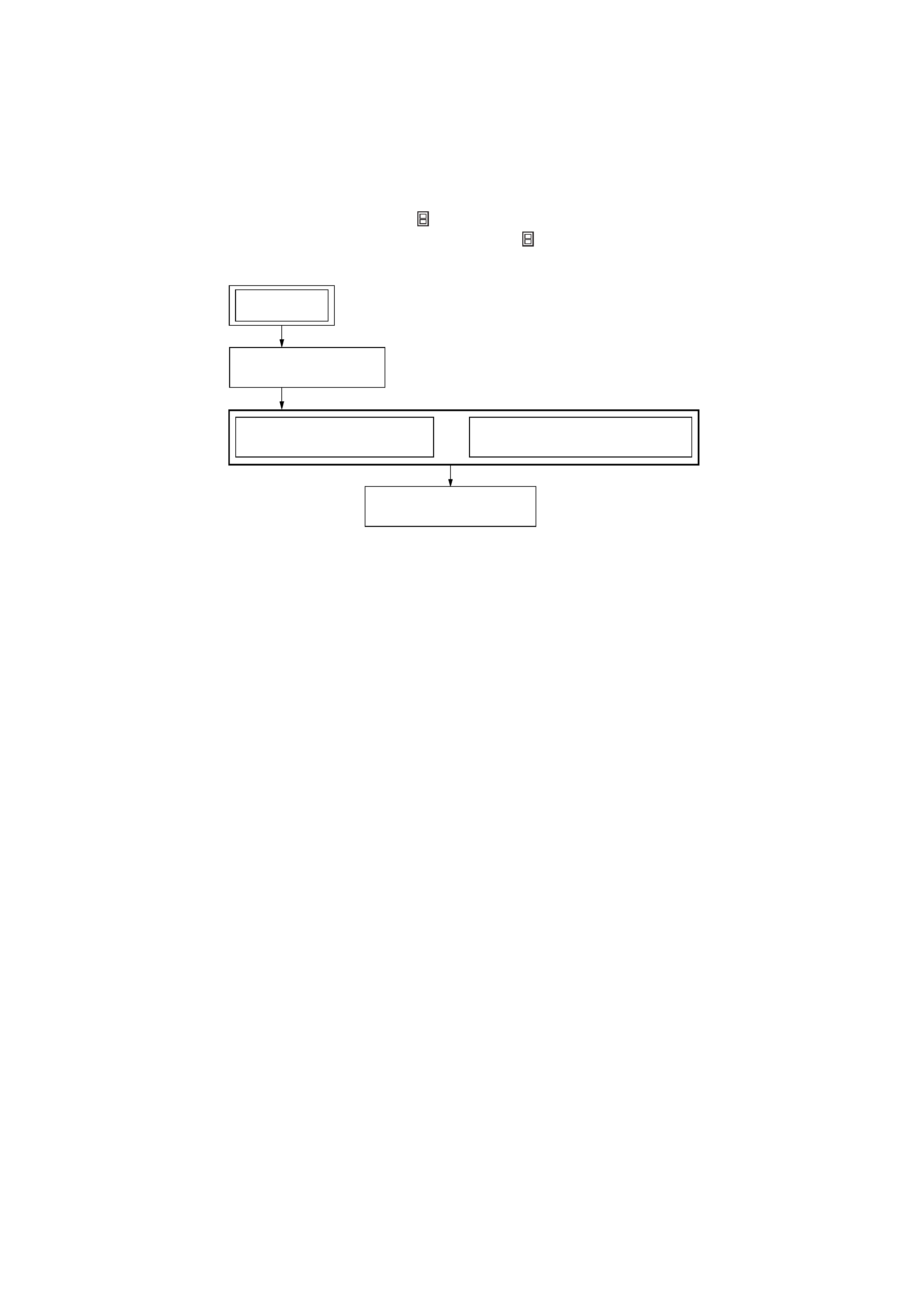
· This set can be disassembled in the order shown below.
3-1.
DISASSEMBLY FLOW
SECTION 3
DISASSEMBLY
3-2. CASE
(Page 6)
3-3. FRONT PANEL SECTION
(Page 6)
3-4. BACK PANEL (DVD) SECTION
(Page 7)
3-5. FRONT AMP BOARD
(Page 7)
SET
Note 1: The process described in
can be performed in any order.
Note 2: Without completing the process described in
, the next process can not be performed.