SERVICE MANUAL
AV AMPLIFIER
AEP Model
UK Model
SPECIFICATIONS
TA-S3
Ver 1.0 2001.05
9-873-874-11
Sony Corporation
2001E0500-1
Home Audio Company
C
2001.5
Shinagawa Tec Service Manual Production Group
TA-S3 is the Amplifier section in
MHC-S3.
Amplifier section
DIN power output (rated) 60 + 60 watts
(6 ohms at 1 kHz, DIN)
Continuous RMS power output (reference)
80 + 80 watts
(6 ohms at 1 kHz, 10%
THD)
Music power output (reference)
150 + 150 watts
(6 ohms at 1 kHz, 10%
THD)
Inputs
VIDEO (AUDIO) IN:
voltage 250 mV,
(phono jacks)
impedance 47 kilohms
MD IN:
voltage 450 mV,
(phono jacks)
impedance 47 kilohms
OPTICAL IN:
(Square optical connector jacks, rear panel)
wavelength
700 nm
Outputs
MD OUT:
voltage 250 mV
(phono jacks)
impedance 1 kilohms
PHONES:
accepts headphones of
(stereo mini jack)
8 ohms or more
FRONT SPEAKER:
accepts impedance of 6 to
16 ohms
SUB WOOFER OUT:
Voltage 1 V,
impedance 1 kilohms
General
Power requirements
230 V AC, 50/60 Hz
Power consumption
180 watts
0.6 watts (during Power
Saving Mode)
Dimensions (w/h/d)
Approx. 280 x 128 x 350 mm
Mass
Approx. 6.2 kg
Design and specifications are subject to change
without notice.

2
TA-S3
SAFETY-RELATED COMPONENT WARNING!!
COMPONENTS IDENTIFIED BY MARK 0 OR DOTTED
LINE WITH MARK 0 ON THE SCHEMATIC DIAGRAMS
AND IN THE PARTS LIST ARE CRITICAL TO SAFE
OPERATION. REPLACE THESE COMPONENTS WITH
SONY PARTS WHOSE PART NUMBERS APPEAR AS
SHOWN IN THIS MANUAL OR IN SUPPLEMENTS PUB-
LISHED BY SONY.
TABLE OF CONTENTS
1.
SERVICING NOTES ............................................... 3
2.
GENERAL ................................................................... 4
3.
DISASSEMBLY
3-1. Disassembly Flow ...........................................................
5
3-2. Cover ...............................................................................
6
3-3. Front Panel Section .........................................................
6
3-4. Back Panel (2CH/VCD) Section ....................................
7
3-5. FRONT AMP Board .......................................................
7
4.
TEST MODE .............................................................. 8
5.
DIAGRAMS
5-1. Note for Printed Wiring Boards
and Schematic Diagrams ................................................ 10
5-2. Printed Wiring Boards FRONT AMP Section ........ 11
5-3. Schematic Diagram FRONT AMP Section (1/2) .... 12
5-4. Schematic Diagram FRONT AMP Section (2/2) .... 13
5-5. Printed Wiring Boards CONTROL Section ............ 14
5-6. Schematic Diagram CONTROL Section ................. 15
5-7. Printed Wiring Boards POWER Section ................. 16
5-8. Schematic Diagram POWER Section ..................... 17
5-9. IC Pin Function Description ........................................... 18
6.
EXPLODED VIEWS
6-1. Cover Section .................................................................. 18
6-2. Front Panel Section ......................................................... 19
6-3. Chassis Section ............................................................... 20
7.
ELECTRICAL PARTS LIST ............................... 21
3
TA-S3
SECTION 1
SERVICING NOTES
This set is a component of the MHC-S3.
The MHC-S3 system configuration is as shown below, and there-
fore it does not operate normally unless all four components are
connected.
In performing the repair, connect all components with the system
cables.
Note: The precaution to the users is described on the label stuck on the
back panel (CD player) and in the troubleshooting section in the
Operation Manual.
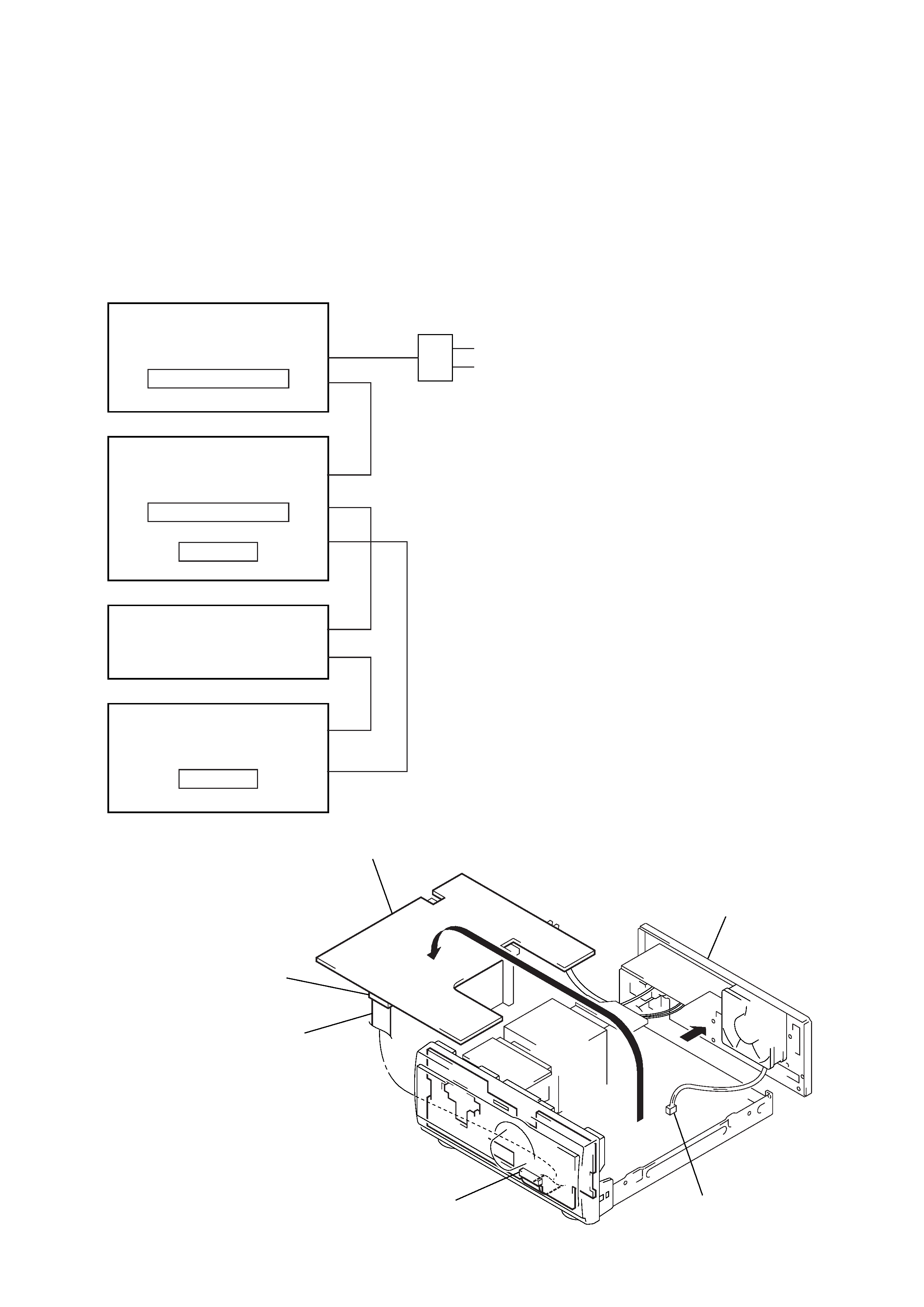
System Configuration:
POWER SUPPLY
AC IN
TA
SYSTEM & CD
µcon
ST
CDP
TC
µcon
TC
DISPLAY
FRONT AMP BOARD SERVICE POSITION
In checking the FRONT AMP board, prepare jig
(extension cable J-2501-087-A: 1.25 mm Pitch, 23 core, Length
300 mm)
(Fig A)
(Fig A)
Turn over the FRONT AMP board with Heat Sink, THP board
and RELAY board connected.
Remove the back panel
(2CD/VCD) section.
Remove the fan motor
connector lead wire.
FRONT AMP board
(CN104)
Connect jig (extension
cable J-2501-087-A
to the FRONT AMP board (CN104)
and PANEL board (CN700).
PANEL board (CN700)
4
TA-S3
SECTION 2
GENERAL
This section is extracted from
instruction manual.
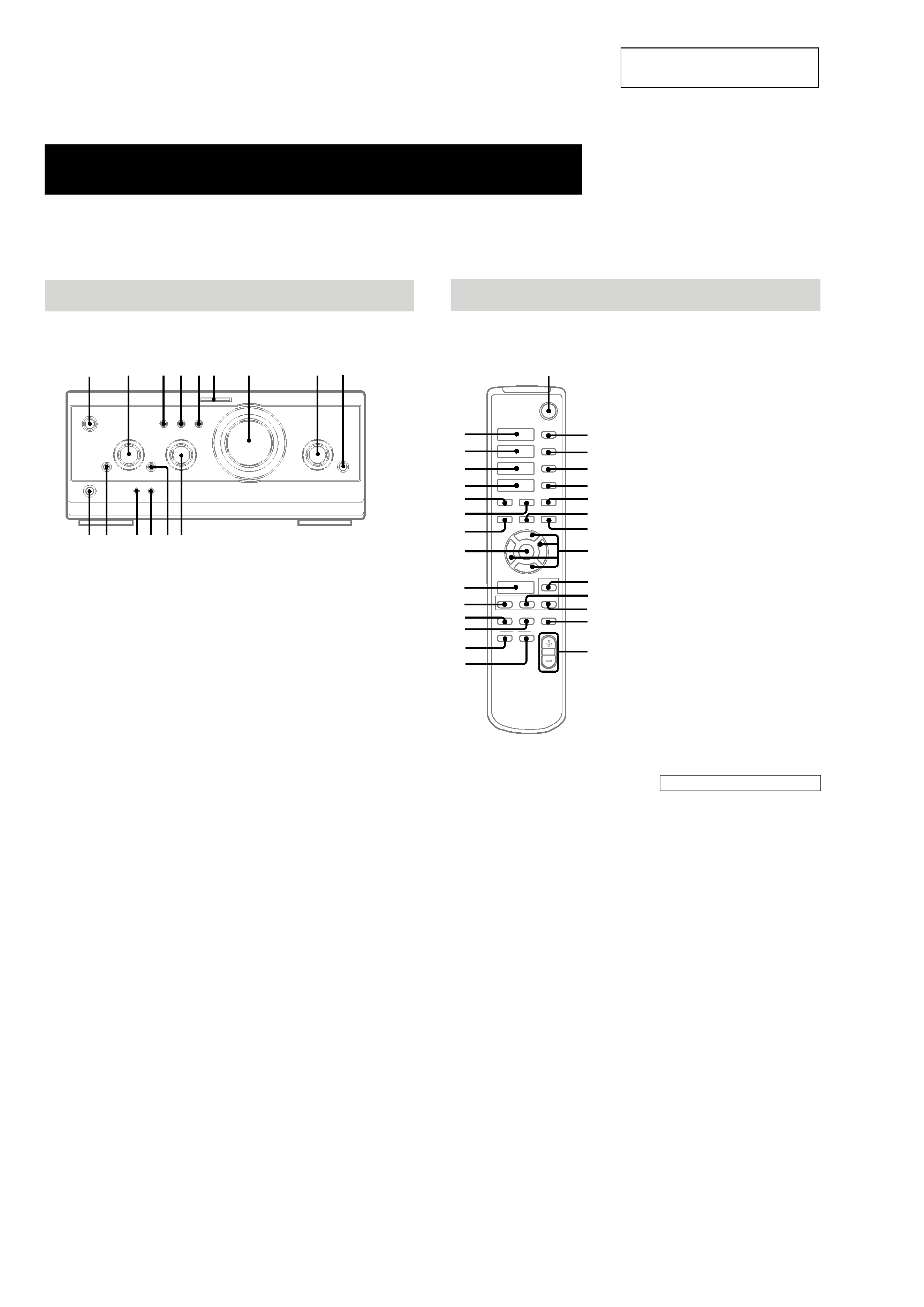
Parts Identification
The items are arranged in alphabetical order.
Refer to the pages indicated in parentheses ( ) for details.
P
o
O
p
6
3 4 5
7
8
2
9
q;
qa
qs
qd
qf
qg
1
DIGITAL 9 (28, 32)
ENTER/O/o/P/p 2 (9, 12, 18,
19, 2227)
EQ qa (24)
EQ ON/OFF qs (9, 24)
FILE SELECT q; (20, 24)
FUNCTION 8 (9, 11, 12, 17, 18,
28)
GROOVE 5 (20)
MOVIE MODE 4 (20, 21)
MULTI CHANNEL DECODING
indicator 6 (22)
MUSIC MODE 3 (20, 21)
PHONES jack qg
SET UP qd (2326)
SUR qf (22)
VOLUME 7
@/1 (power) 1 (8, 9, 32)
Main unit
A/V amplifier
x
hH
H
hH
O
o
Pp
M
m
X
>
.
1
wa
qf
9
wf
wd
ws
qj
2
3
4
5
0
qs
qa
qd
6
7
8
qh
qg
ql
qk
w;
wk
wj
wh
wg
Remote Control
CD H wk (11, 12)
CHECK 3 (12)
CLEAR 4 (12)
CLOCK/TIMER SELECT qg
(19, 27)
CLOCK/TIMER SET qh (9, 18,
26)
DBFB qd (20)
DISPLAY qk (10, 13, 15, 26, 32)
D.SKIP 2 (11)
ENTER wa (9, 12, 14, 15, 18, 19,
2227)
EQ qa (24)
EQ ON/OFF qs (9, 24)
FUNCTION w; (9, 11, 12, 17, 18,
28)
GROOVE qj (20)
SET UP q; (2326)
SLEEP 5 (26)
SUR ql (22)
TAPE A hH wj (16)
TAPE B hH wh (16, 17)
TUNER/BAND wg (14)
TUNING + 7 (14)
TUNING ws (14)
VOL +/ qf
BUTTON DESCRIPTIONS
@/1 (power) 1
X (pause) 8
x (stop) 6
. (go back) wf
> (go forward) wd
m (rewind) ws
M (fast forward) 7
O
/o/P/p 9
5
TA-S3
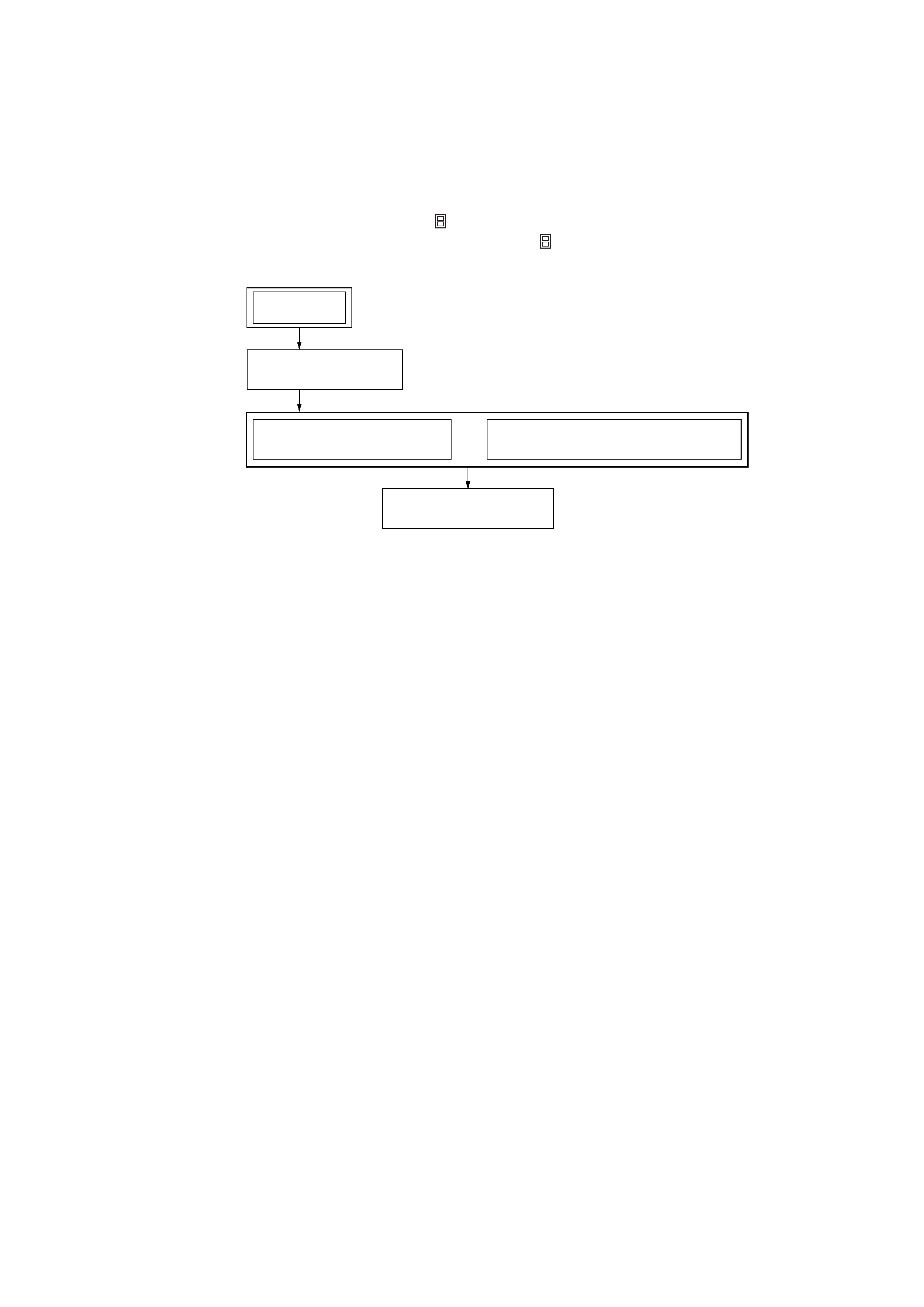
· This set can be disassembled in the order shown below.
3-1.
DISASSEMBLY FLOW
SECTION 3
DISASSEMBLY
3-2. COVER
(Page 6)
3-3. FRONT PANEL SECTION
(Page 6)
3-4. BACK PANEL (2CH/VCD) SECTION
(Page 7)
3-5. FRONT AMP BOARD
(Page 7)
SET
Note 1: The process described in
can be performed in any order.
Note 2: Without completing the process described in
, the next process can not be performed.