SERVICE MANUAL
Sony Corporation
Audio Company
Published by Sony Engineering Corporation
US Model
SYSTEM INTEGRATION 2CH AMPLIFIER
9-879-354-01
2004L1678-1
© 2004.12
Ver. 1.0 2004.12
SPECIFICATIONS
TA-MR2ES
Continuous average power output (FTC):
35 W per channel min. RMS at 8 ohms,
both channels driven from 20 Hz to
20 kHz with no more than 0.09 %
THD.
40 W per channel min. RMS at 4 ohms,
both channels driven from 20 Hz to
20 kHz with no more than 0.09 %
THD.
Frequency responce:
5 Hz 100 kHz + 0.5/2 dB
Residual noise (A-weighted):
150
µV or less
Channel separation (1 kHz/10 kHz):
(input 4.7 k ohms terminated)
60 dB/45 dB
Signal-to-noise ratio:
94 dB (A-weighted filter, 150 mV input)
Audio input
Sensitivity:
150 mV
Impedance:
50 k ohms
Audio output
Voltage:
minimum 2 V without clipped
Impedance:
1 k ohms
S/N:
102 dB (A-weighted filter, 2 V output)
General
12V trigger IN:
accept 10 ~ 12 V of trigger
12V trigger OUT:
300 mA max
IR input:
accept up to 40 kHz IR modulation
frequency
IR output:
buffered, 5 V
Power requirements:
120 VAC, 60 Hz
Power consumption:
100 W
Dimensions:
430
× 67 × 350 mm (w/h/d)
Mass:
6.5 kg
Design and specifications are subject to change without notice.
Unpacking
· TA-MR2ES amplifier
· AC power cord
· Installation Manual
· Rack-mount brackets (2)
· Screw (6)
2
TA-MR2ES
TABLE OF CONTENTS
1.
GENERAL ................................................................... 3
2.
TEST MODE ............................................................... 4
3.
DIAGRAMS
3-1.
Block Diagram AUDIO Section ................................
6
MAIN/POWER Section ............................................
7
3-2.
Printed Wiring Board
POWER SWITCH/INLET Section ...........................
8
3-3.
Schematic Diagram AMP Section (1/3) ...................
9
3-4.
Printed Wiring Board AMP Section ......................... 10
3-5.
Schematic Diagram AMP Section (2/3) ................... 11
3-6.
Printed Wiring Board MAIN COMB Section .......... 12
3-7.
Schematic Diagram AMP Section (3/3) ................... 13
4.
EXPLODED VIEWS
4-1.
Front Panel Section ......................................................... 17
4-2.
Chassis Section ................................................................ 18
5.
ELECTRICAL PARTS LIST .................................. 19
Flexible Circuit Board Repairing
· Keep the temperature of the soldering iron around 270 °C
during repairing.
· Do not touch the soldering iron on the same conductor of the
circuit board (within 3 times).
· Be careful not to apply force on the conductor when soldering
or unsoldering.
Notes on chip component replacement
· Never reuse a disconnected chip component.
· Notice that the minus side of a tantalum capacitor may be
damaged by heat.
SAFETY-RELATED COMPONENT WARNING!!
COMPONENTS IDENTIFIED BY MARK 0 OR DOTTED LINE
WITH MARK 0 ON THE SCHEMATIC DIAGRAMS AND IN
THE PARTS LIST ARE CRITICAL TO SAFE OPERATION.
REPLACE THESE COMPONENTS WITH SONY PARTS WHOSE
PART NUMBERS APPEAR AS SHOWN IN THIS MANUAL OR
IN SUPPLEMENTS PUBLISHED BY SONY.
UNLEADED SOLDER
Boards requiring use of unleaded solder are printed with the lead-
free mark (LF) indicating the solder contains no lead.
(Caution: Some printed circuit boards may not come printed with
the lead free mark due to their particular size)
: LEAD FREE MARK
Unleaded solder has the following characteristics.
· Unleaded solder melts at a temperature about 40 °C higher
than ordinary solder.
Ordinary soldering irons can be used but the iron tip has to be
applied to the solder joint for a slightly longer time.
Soldering irons using a temperature regulator should be set to
about 350
°C.
Caution: The printed pattern (copper foil) may peel away if
the heated tip is applied for too long, so be careful!
· Strong viscosity
Unleaded solder is more viscou-s (sticky, less prone to flow)
than ordinary solder so use caution not to let solder bridges
occur such as on IC pins, etc.
· Usable with ordinary solder
It is best to use only unleaded solder but unleaded solder may
also be added to ordinary solder.
SAFETY CHECK-OUT
After correcting the original service problem, perform the following
safety check before releasing the set to the customer:
Check the antenna terminals, metal trim, "metallized" knobs, screws,
and all other exposed metal parts for AC leakage.
Check leakage as described below.
LEAKAGE TEST
The AC leakage from any exposed metal part to earth ground and
from all exposed metal parts to any exposed metal part having a
return to chassis, must not exceed 0.5 mA (500 microamperes.).
Leakage current can be measured by any one of three methods.
1. A commercial leakage tester, such as the Simpson 229 or RCA
WT-540A. Follow the manufacturers' instructions to use these
instruments.
2. A battery-operated AC milliammeter. The Data Precision 245
digital multimeter is suitable for this job.
3. Measuring the voltage drop across a resistor by means of a
VOM or battery-operated AC voltmeter. The "limit" indication
is 0.75 V, so analog meters must have an accurate low-voltage
scale. The Simpson 250 and Sanwa SH-63Trd are examples
of a passive VOM that is suitable. Nearly all battery operated
digital multimeters that have a 2 V AC range are suitable. (See
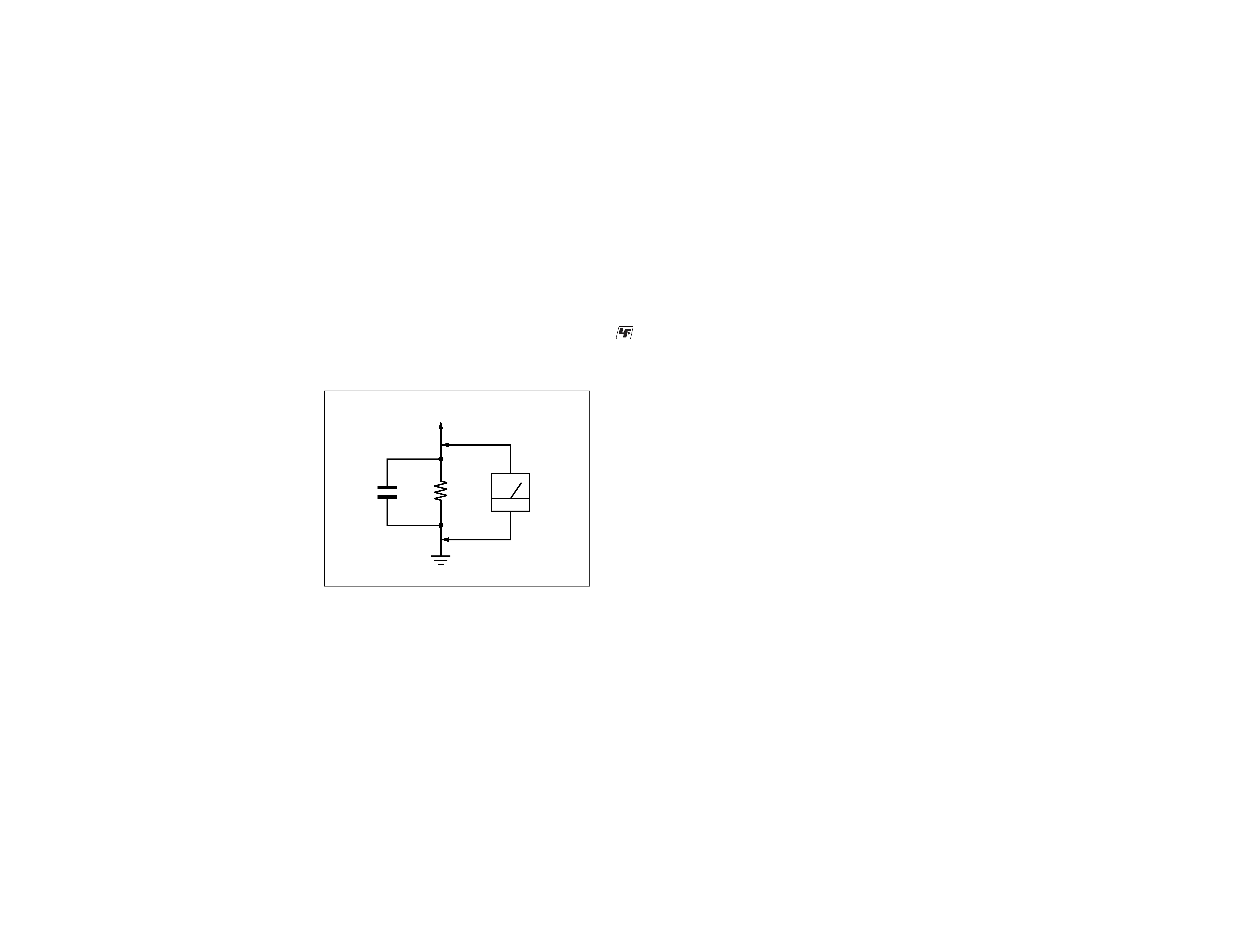
Fig. A)
Fig. A.
Using an AC voltmeter to check AC leakage.
1.5 k
0.15
µF
AC
voltmeter
(0.75 V)
To Exposed Metal
Parts on Set
Earth Ground
3
TA-MR2ES
SECTION 1
GENERAL
This section is extracted
from instruction manual.
ON
POWER
IN USE
ATTENUATOR
L
R
++
*
*To remove the cover
Press either ends of the cover lid to remove the cover.
After you have finished adjusting the ATTENUATOR
L/R, place the cover lid back to its original position.
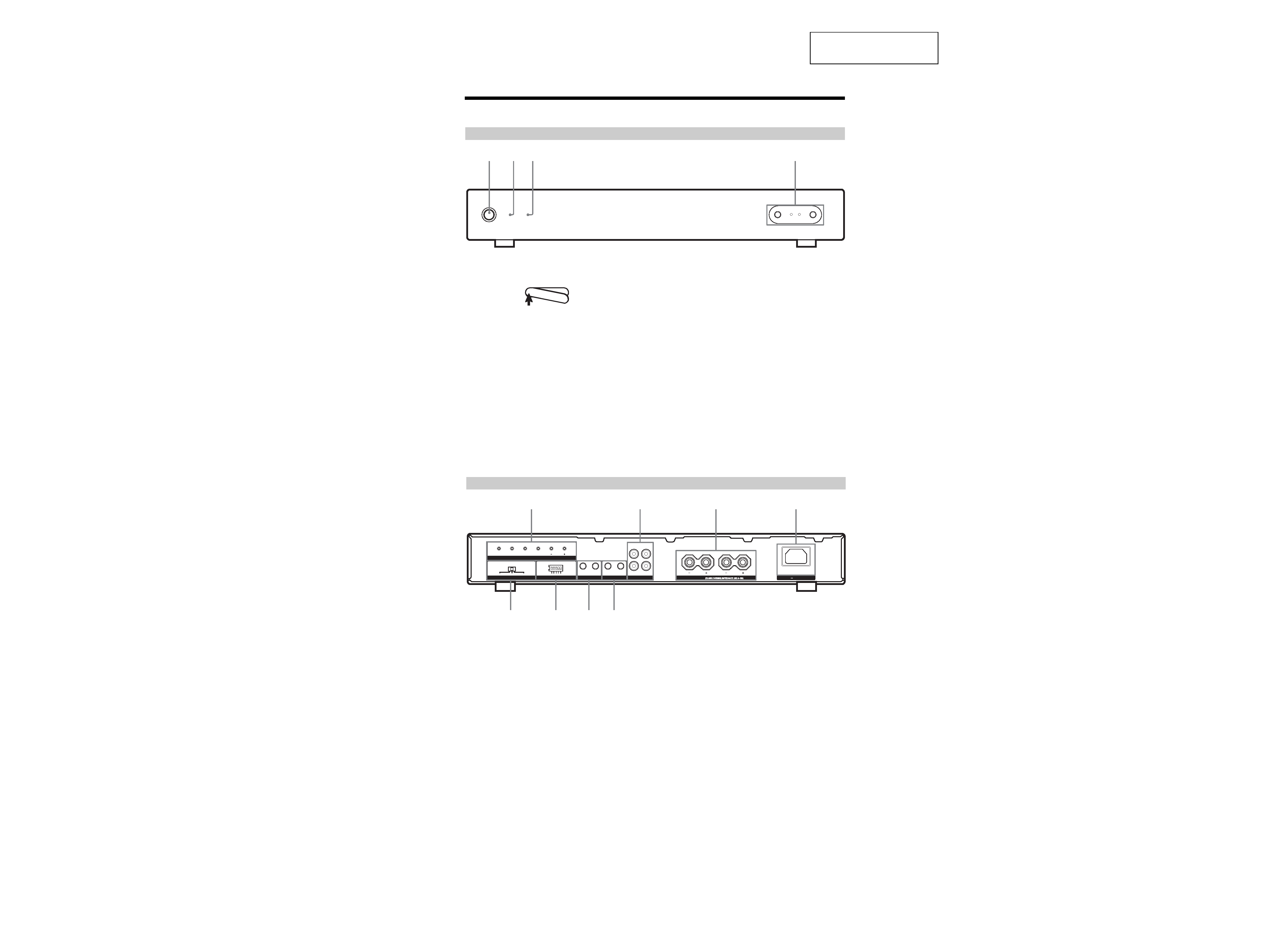
Front panel of the amplifier
1
POWER switch
Press to turn the power on or off.
2
3
ON indicator
The ON indicator lights up as follows:
green: the power is on.
green (flashing three times): the amplifier's memory
is cleared.
off: the power is off.
IN USE indicator
The IN USE indicator lights up as follows:
green: the amplifier is in use.
green (flashing): the IR ID TEST switch is set to
"ON".
green (fast flashing): the IR TEST function is in
progress.
red (flashing): "PROTECTION" mode is turned on.
off: the amplifier is not in use.
4
12
3
4
ATTENUATOR L/R
Adjusts the maximum volume level of this amplifier to
match the room and the speakers used.
Parts and Controls
Rear panel of the amplifier
IR TEST
IR ID
AUTO POWER SELECTOR
12V TRIGGER
IR REMOTE
AUDIO
R
R
L
IN
OUT
IN
IR IN
4
3
2
1TEST
12V TRIGGER
IR IN
AUDIO SENSING
OFF
ON
VOL
VOL
POWER
OFF
POWER
ON
POWER
ON / OFF
MUTING
IR OUT
OUT
L
SPEAKERS
AC IN
5
IR TEST buttons (page 12)
Press the appropriate button to output the IR codes
you want to teach through the IR OUT terminal.
6
AUDIO jacks (page 10)
a) AUDIO IN
RCA jacks for stereo line level audio input from a
multi-room system.
b) AUDIO OUT
RCA jacks for looping out to another amplifier or
component.
Note
This is a buffered audio connection, and this loop-through is
active even when the IN USE indicator is off, as long as the
AC power cord is plugged in and the POWER switch is on.
7
SPEAKERS (page 10)
Terminal which accepts speaker wire sizes up to
12AWG.
Leave the AC power cord unplugged when you hook
up speaker cables.
8
AC IN (page 10)
Removable power cord for easy serviceability of the
amplifier.
9
12V TRIGGER jacks (page 10)
a) IN
A 3.5 mm monaural mini jack to turn on the amplifier
via a 12-volt trigger input.
b) OUT
Enables the looping of amplifier control from one to
the next to trigger multiple amplifiers from a 12-volt
trigger output.
q;
IR REMOTE jacks (page 10)
a) IR IN
Connects to an outboard IR repeater system so you
can operate the amplifier from a distant room.
b) IR OUT
A 3.5 mm monaural mini jack for the connection of an
IR emitter to control other components individually.
IR signals received will be routed to the IR sensor of
the other components.
Outputs IR from the IR TEST system built into the rear
of the amplifier.
qa
IR ID switches (page 12)
Select from 12 discrete IR code tables to communicate
with up to 12 TA-MR2ES amplifiers (with individual
IR ID) on one IR repeater network.
qs
AUTO POWER SELECTOR switch (page 11)
Selects the method for activating the amplifier.
5
qs
qa
q;
9
68
7
4
TA-MR2ES
1. MEMORY CLEAR
Procedure:
1
Select the TEST switch to "ON" of the IR ID at back panel.
2
Press the POWER OFF key at back panel in advance and
simultaneously press the POWER ON key at front panel.
3
See the condition of two LEDs as follows.
2. VERSION show
Procedure:
1
Press the VOL+ key and POWER OFF key of IR TEST in
advance, and simultaneously press the POWER ON key at
front panel.
2
If the POWER LED turn on while 250ms, the version
will show you major version.
If IN USE LED turn on while 250ms, the version will
show you minor version.
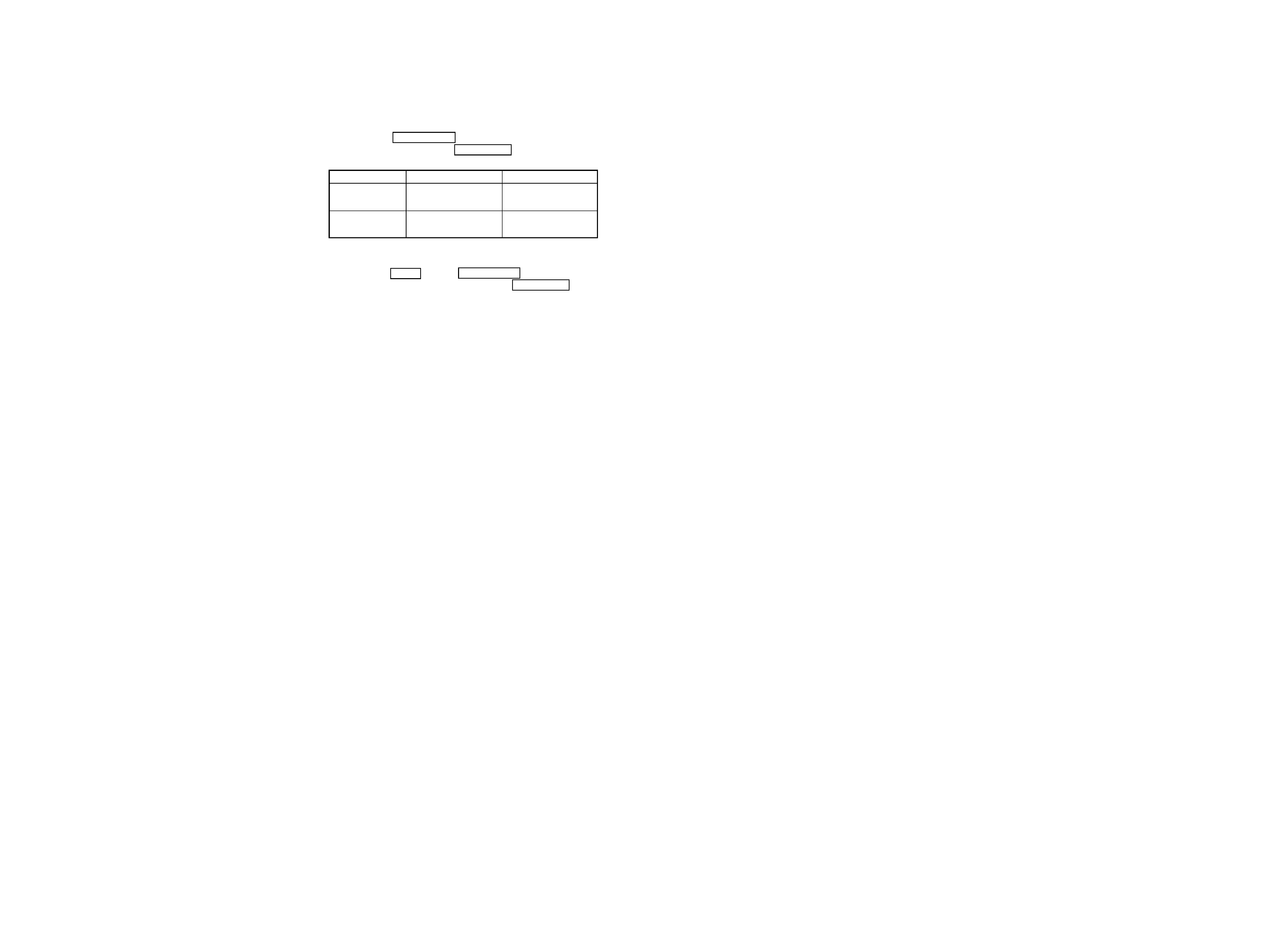
3
POWER LED goes on, IN USE LED is blinking.
POWER LED
IN USE LED
FIRST
slow blinking 3times
off while power LED
CONDITION
(each 1 sec)
blinking
AFTER
ON
slow blinking each 1
sec
SECTION 2
TEST MODE
5
5
TA-MR2ES
TA-MR2ES
SECTION 3
DIAGRAMS
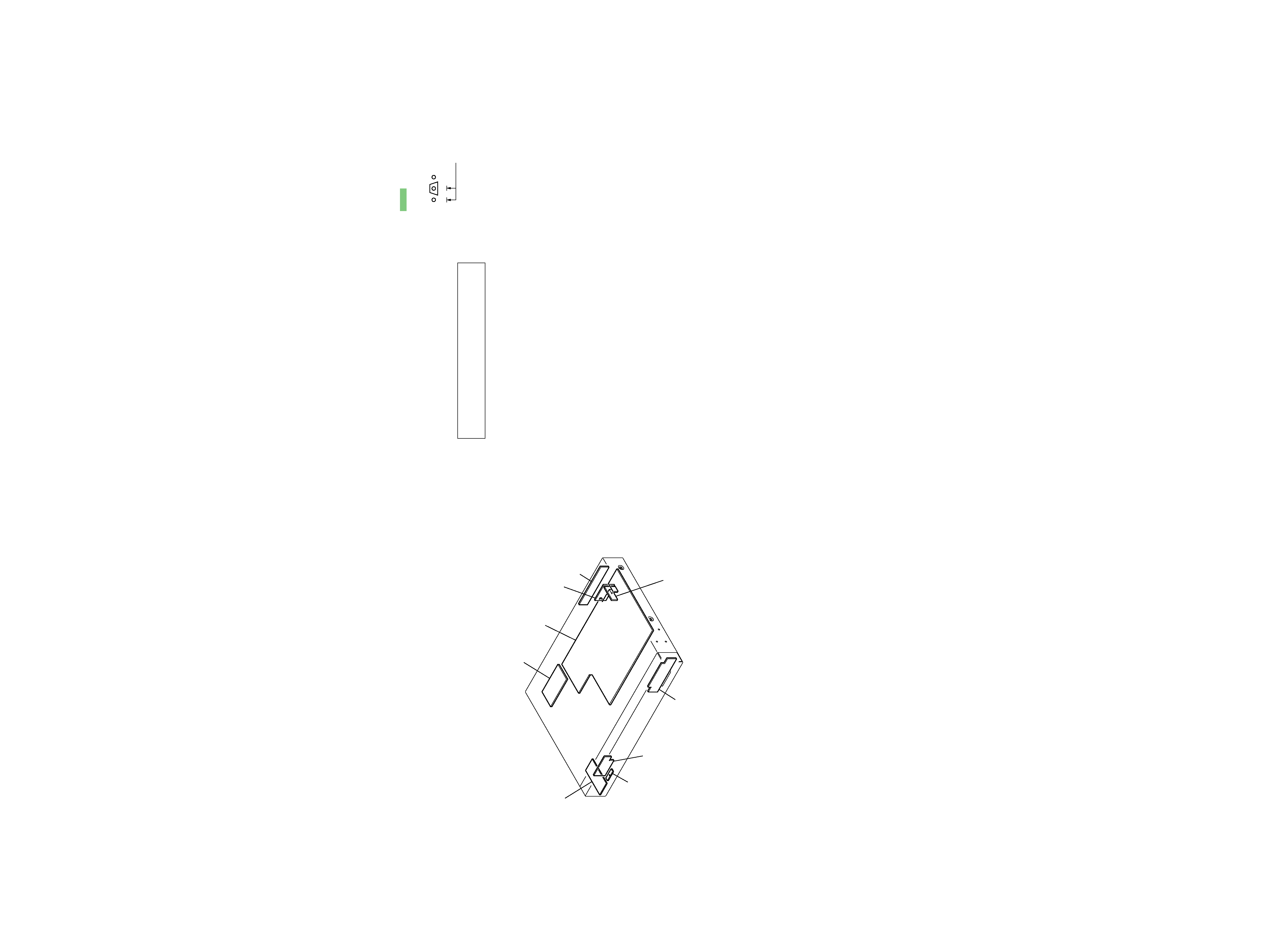
POWER SWITCH board
STOPPER board
LED board
VR board
JUMPER board
TACT SWITCH board
ID board
AMP board
INLET board
· Circuit Boards Location
For Schematic Diagrams.
Note:
· All capacitors are in
µF unless otherwise noted. (p: pF)
50 WV or less are not indicated except for electrolytics and
tantalums.
· All resistors are in
and 1/4 W or less unless otherwise
specified.
·
%
: indicates tolerance.
·
f
: internal component.
· 2 : nonflammable resistor.
· 5 : fusible resistor.
· C : panel designation.
· A : B+ Line.
· B : B Line.
·Voltages and waveforms are dc with respect to ground un-
der no-signal (detuned) conditions.
No mark: POWER ON
*
: Imposible to measure
·Voltages are taken with a VOM (Input impedance 10 M
).
Voltage variations may be noted due to normal production
tolerances.
·Waveforms are taken with a oscilloscope.
· Circled numbers refer to waveforms.
· Signal path.
F
: AUDIO
For Printed Wiring Boards.
Note:
· X : parts extracted from the component side.
·
a
: Through hole.
·
f
: internal component.
·
: Pattern from the side which enables seeing.
Note: The components identified by mark 0 or dotted
line with mark 0 are critical for safety.
Replace only with part number specified.
B
These are omitted.
CE
Q
THIS NOTE IS COMMON FOR PRINTED WIRING BOARDS AND SCHEMATIC DIAGRAMS.
(In addition to this, the necessary note is printed in each block.)