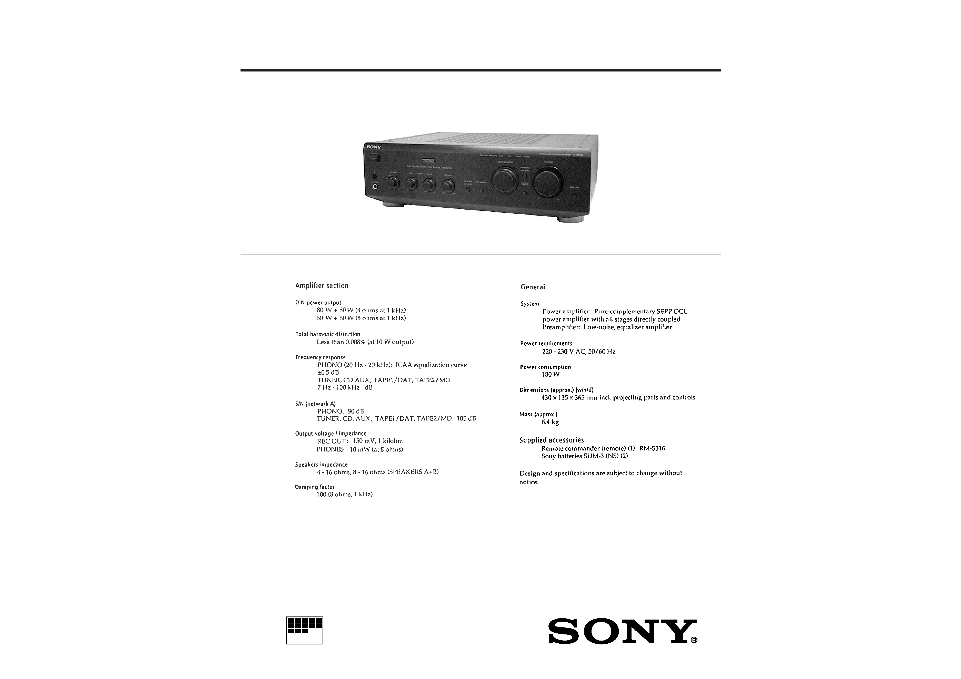
TA-FE610R
AEP Model
SERVICE MANUAL
INTEGRATED STEREO AMPLIFIER
MICROFILM
SPECIFICATIONS

-- 2 --
TABLE OF CONTENTS
1. GENERAL .................................................................... 3
2. ELECTRICAL ADJUSTMENT ....................................... 4
3. DIAGRAMS
3-1.
Circuit Boards Location ....................................................... 5
3-2.
IC Pin Function
· IC902 Input Control LED Driver
(TMP47C103N-JP47) ....................................................... 6
3-3.
Schematic Diagram -- Panel Section -- .............................. 7
3-4.
Printed Wiring Board -- Panel Section -- ........................... 9
3-5.
Schematic Diagram -- Main A Section -- ........................ 11
3-6.
Printed Wiring Board -- Main A Section -- ..................... 13
3-7.
Schematic Diagram -- Main B Section -- ........................ 15
3-8.
Printed Wiring Board -- Main B Section -- ..................... 17
4. EXPLODED VIEWS
4-1.
Front Panel Section ............................................................ 19
4-2.
Chassis Section ................................................................... 20
5. ELECTRICAL PARTS LIST ..................................... 21
SAFETY-RELATED COMPONENT WARNING !!
COMPONENTS IDENTIFIED BY MARK
! OR DOTTED LINE
WITH MARK
! ON THE SCHEMATIC DIAGRAMS AND IN
THE PARTS LIST ARE CRITICAL TO SAFE OPERATION.
REPLACE THESE COMPONENTS WITH SONY PARTS
WHOSE PART NUMBERS APPEAR AS SHOWN IN THIS
MANUAL OR IN SUPPLEMENTS PUBLISHED BY SONY.
-- 3 --
SECTION 1
GENERAL
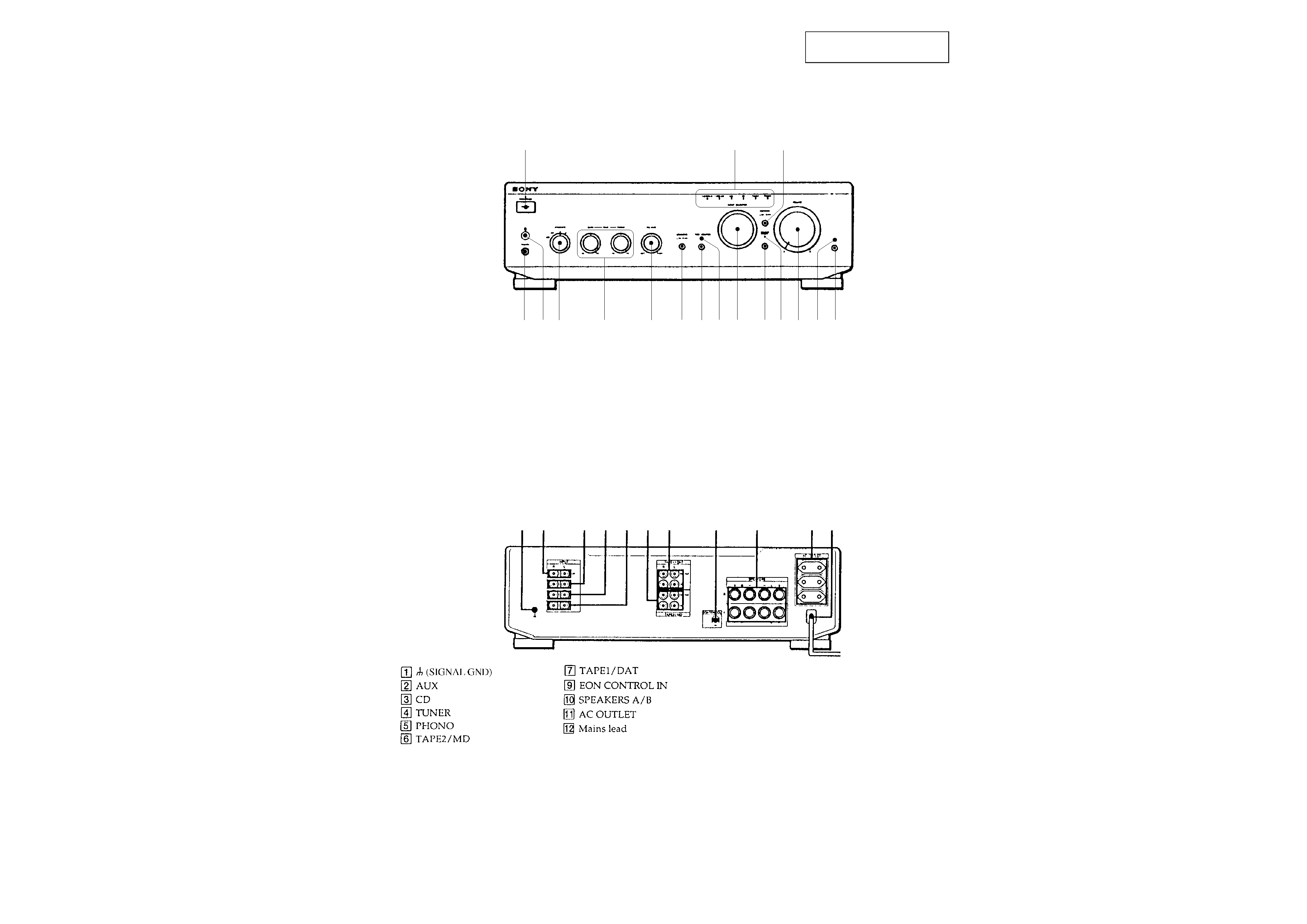
location of parts and controls
FRONT PANEL
1 POWER switch
2 INPUT SELECTOR indicator
3 SUBSONIC switch
4 EON LINK switch
5 EON LINK indicator
6 VOLUME control
7 SOURCE DIRECT indicator
8 SOURCE DIRECT switch
9 INPUT SELECTOR control
0 TAPE MONITOR indicator
!¡ TAPE MONITOR switch
!TM LOUDNESS switch
!£ BALANCE control
!¢ TONE (BASS, TREBLE) control
! SPEAKERS selector
!§ Remote control sensor
!¶ PHONES jack
REAR PANEL
1 23 4 56 7
9
0
!¡ !TM
54
6
7
8
9
0
!¡
!TM
!£
!¢
!
!§
!¶
1
23
This section is extracted from
instruction manual.
-- 4 --
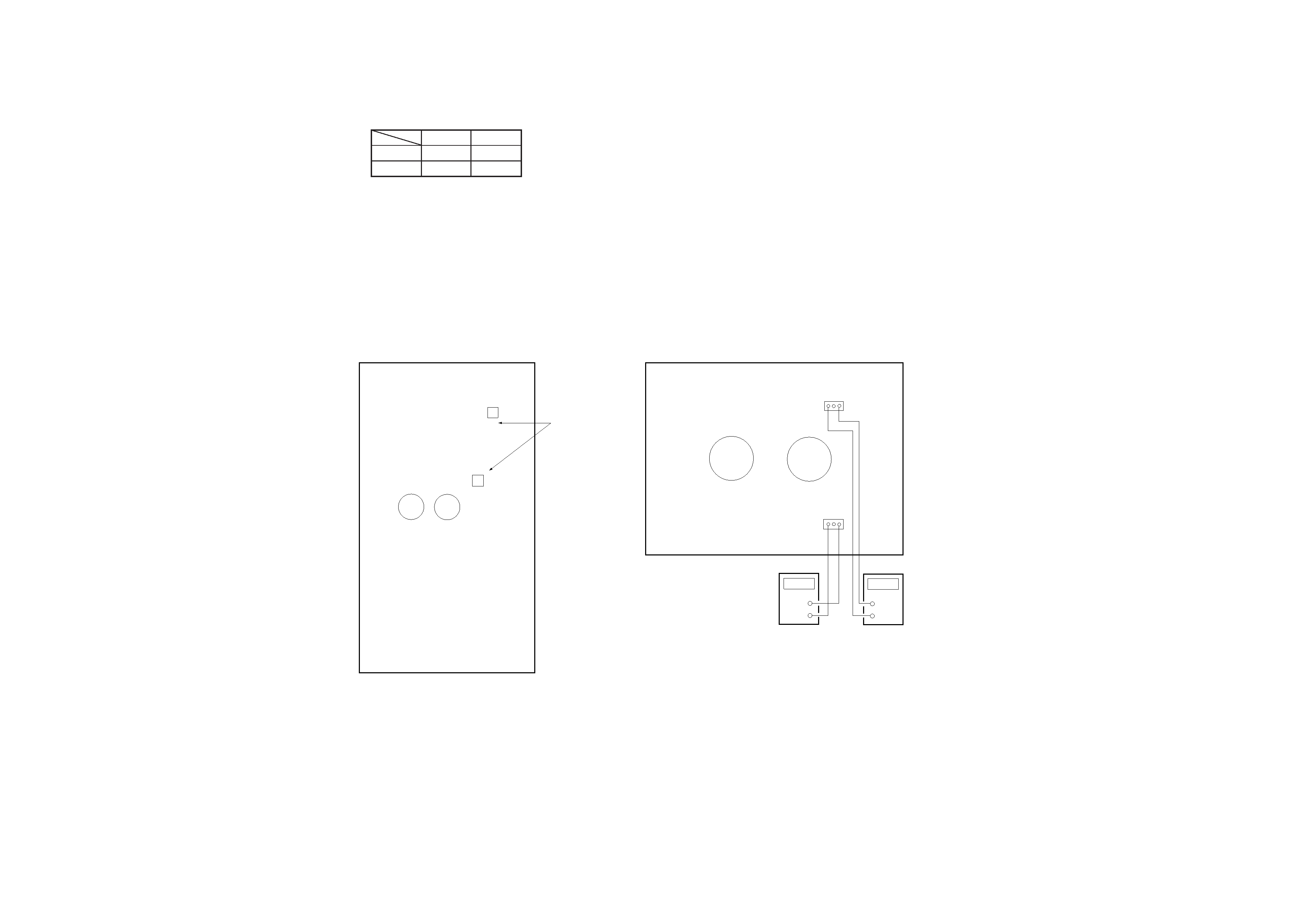
SECTION 2
ELECTRICAL ADJUSTMENT
Bias Adjustment
1.
Rotate fully the bias adjusting semi-fixed resistors (RV301,
RV351) to the MIN position (counterclockwise).
2.
Connect a digital voltmeter to the CN406 and CN407.
1 pin
3 pin
+
+
CN406
CN407
3.
Set the slide regulator to 0V, and press the POWER button
(ON) on the set.
4.
Raise gradually the slide regulator voltage up to the rated
voltage (230 V).
5.
At this time, confirm that the SP relay is turned on (it will
click).
6.
Adjust the RV301 and RV351 so that a reading of digital
voltmeter is 10 mV to 15 mV.
7.
Return the slidack to 0 V, and press the POWER button (OFF)
on the set.
Adjustment Location :
[MAIN A BOARD] -- COMPONENT SIDE --
C322
C372
RV351
RV301
BIAS
Adjustment
`
`
Test Point Location :
[MAIN B BOARD] -- COMPONENT SIDE --
CN406
1
3
C409
C459
CN407
1
3
+
+
DIGITAL
VOLTMETER
DIGITAL
VOLTMETER
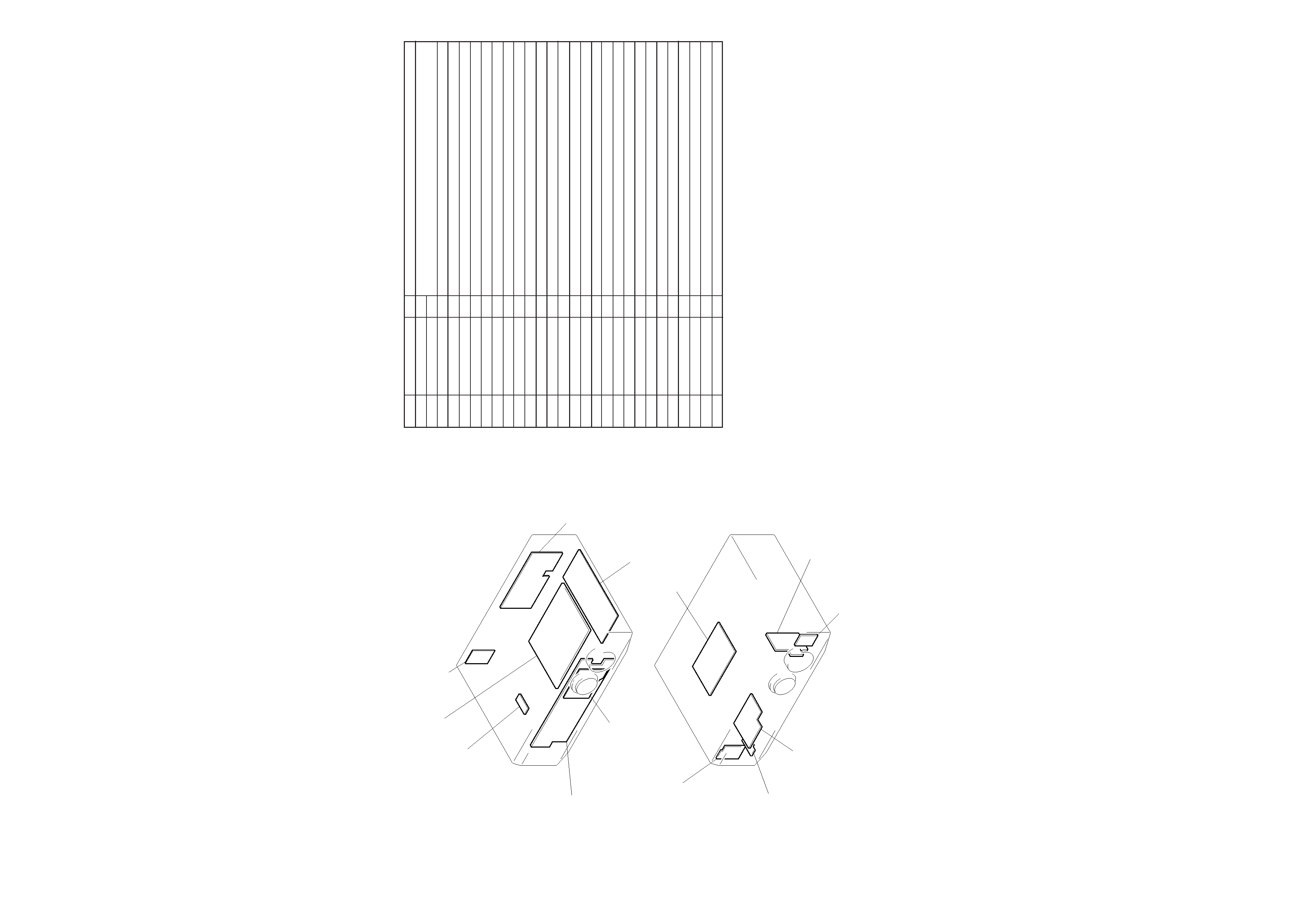
SECTION 3
DIAGRAMS
3-1. CIRCUIT BOARDS LOCATION
MAIN B board
TRANS board
PANEL board
LED board
MAIN A board
INPUT board
OUTLET board
PRO IND board
HP board
SP SW board
EON board
VOL board
SP TM board
I/O
Function
· IC902 Input Control LED Drive (TMP47C103N-JP47)
Pin No.
3-2. IC PIN FUNCTION
Pin Name
O
I
I
I
O
O
I
I
I
I
O
O
O
--
O
O
O
O
O
I
I
I
O
O
O
O
I
--
1
2
3
4
5
6
7
8
9
10
11
12
13
14
15
16
17
18
19
20
21
22
23
24
25
26
27
28
X OUT
X IN
RESET
PMD
VOL +
VOL
SW 0
SW 1
SW 2
EON
PHONO
TUNER
CD
GND
AUX
DAT
TAPE
MON
PRY
PKY
MON
SIRCS
MUTE
SCE
SDT
SCK
STOP
+3V
System clock. (4MHz)
Reset input.
Mode select input.
Motor drive output (+).
Motor drive output ().
Rotary switch input (CD).
Rotary switch input (TUNER).
Rotary switch input (PHONO).
EON signal input.
PHONO LED drive output.
TUNER LED drive output.
CD LED drive output.
Ground.
AUX LED drive output.
TAPE "2" LED drive output.
TAPE "1" LED drive output.
MONITOR output.
Power relay output.
Power key input.
MONITOR input.
SIRCS input.
Muting output.
Chip enble output.
Serial data output.
Serial clock output.
STOP input.
+3V Power supply.
-- 5 --
-- 6 --