TA-FE310R/FE510R
AEP Model
TA-FE310R/FE510R
UK Model
TA-FE310R
SERVICE MANUAL
INTEGRATED STEREO AMPLIFIER
MICROFILM
SPECIFICATIONS
Photo : TA-FE510R
Amplifier section
DIN power output
TA-FE510R: 80 W+80 W (4 ohms at 1 kHz)
60 W+60 W (8 ohms at 1 kHz)
TA-FE310R: 55 W+55 W (4 ohms at 1 kHz)
45 W+45 W (8 ohms at 1 kHz)
Frequency response
PHONO (20 Hz-20 kHz): RIAA equalization curve
±0.5 dB
TUNER, CD, AUX, TAPE1/DAT,
TAPE2/MD: 7 Hz-70 kHz
dB
S/N (network A)
PHONO: 80dB
TUNER, CD, AUX, TAPE1/DAT,
TAPE2/MD: 105 dB
Output voltage/ impedance
REC OUT: 200 mV, 1 kilohm
PHONES: 5 mW (at 8 ohms)
Speakers impedance:
4-16 ohms, 8-16 ohms (SPEAKERS A+B)
Damping factor
80 (8 ohms, 1 kHz)
General
System
Power amplifier: Pure-complementary SEPP OCL
power amplifier with all stages directly coupled
Preamplifier. Low-noise, equalizer amplifier
Power requirements
Models not supplied with a voltage selector:
220-230 V AC, 50/60 Hz
Power consumption
TA-FE510R: 160 W
TA-FE310R: 120 W
Dimensions (approx.) (w/h/d):
430
×105×300 mm
incl. projecting parts and controls
Mass (approx.)
TA-FE510R: 4.8 kg
TA-FE310R: 4.3 kg
Supplied accessories
Remote commander (remote) (1)
RM-S315
Sony batteries SUM-3 (NS) (2)
Design and specifications are subject to change without
notice.
-- 2 --
1.
GENERAL
1-1.
Index to Parts and Controls ................................................ 2
2.
DIAGRAMS
2-1.
Circuit Boards Location ..................................................... 3
2-2.
IC Pin Function Description ............................................... 4
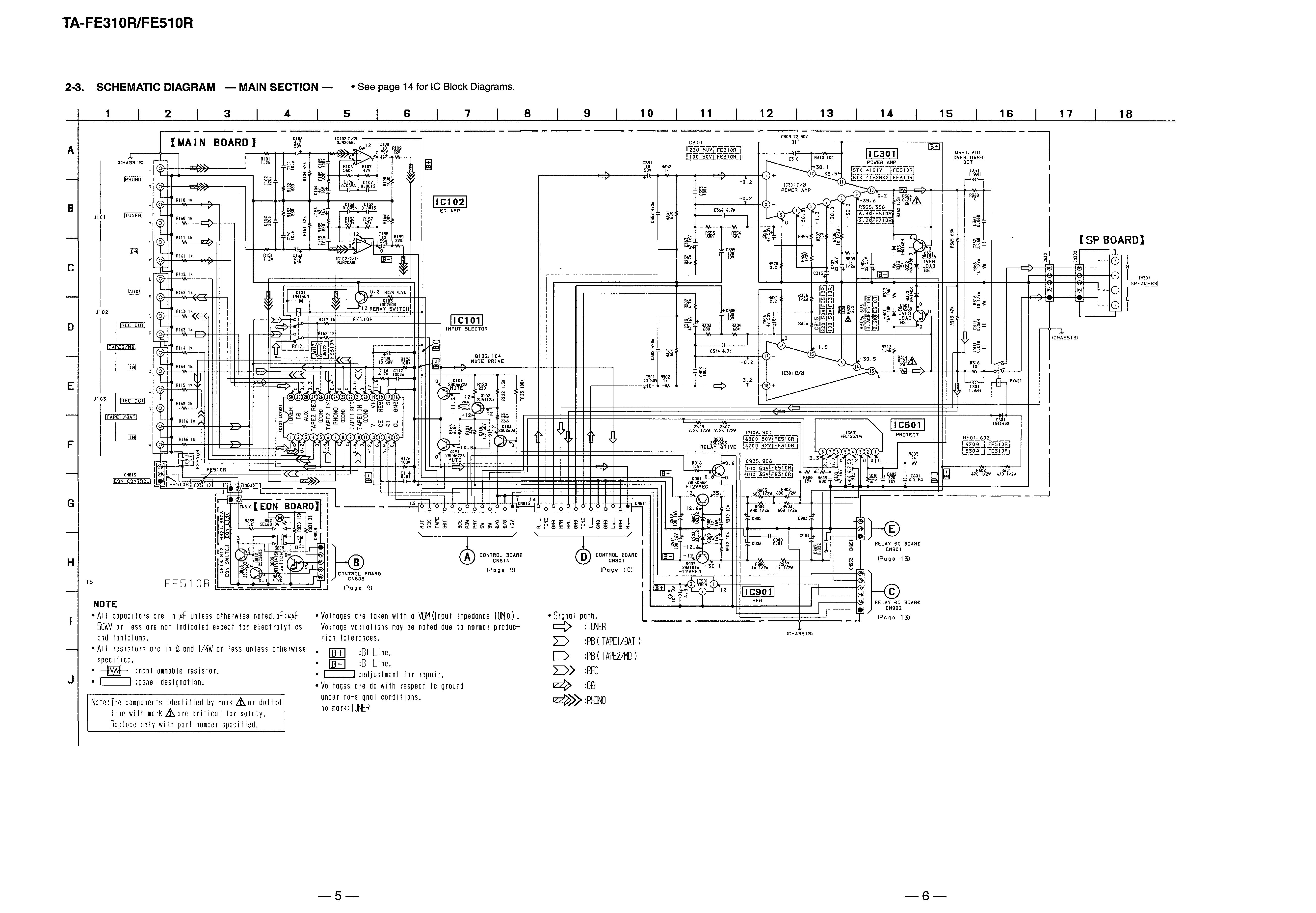
2-3.
Schematic Diagram -- Main Section -- ............................ 5
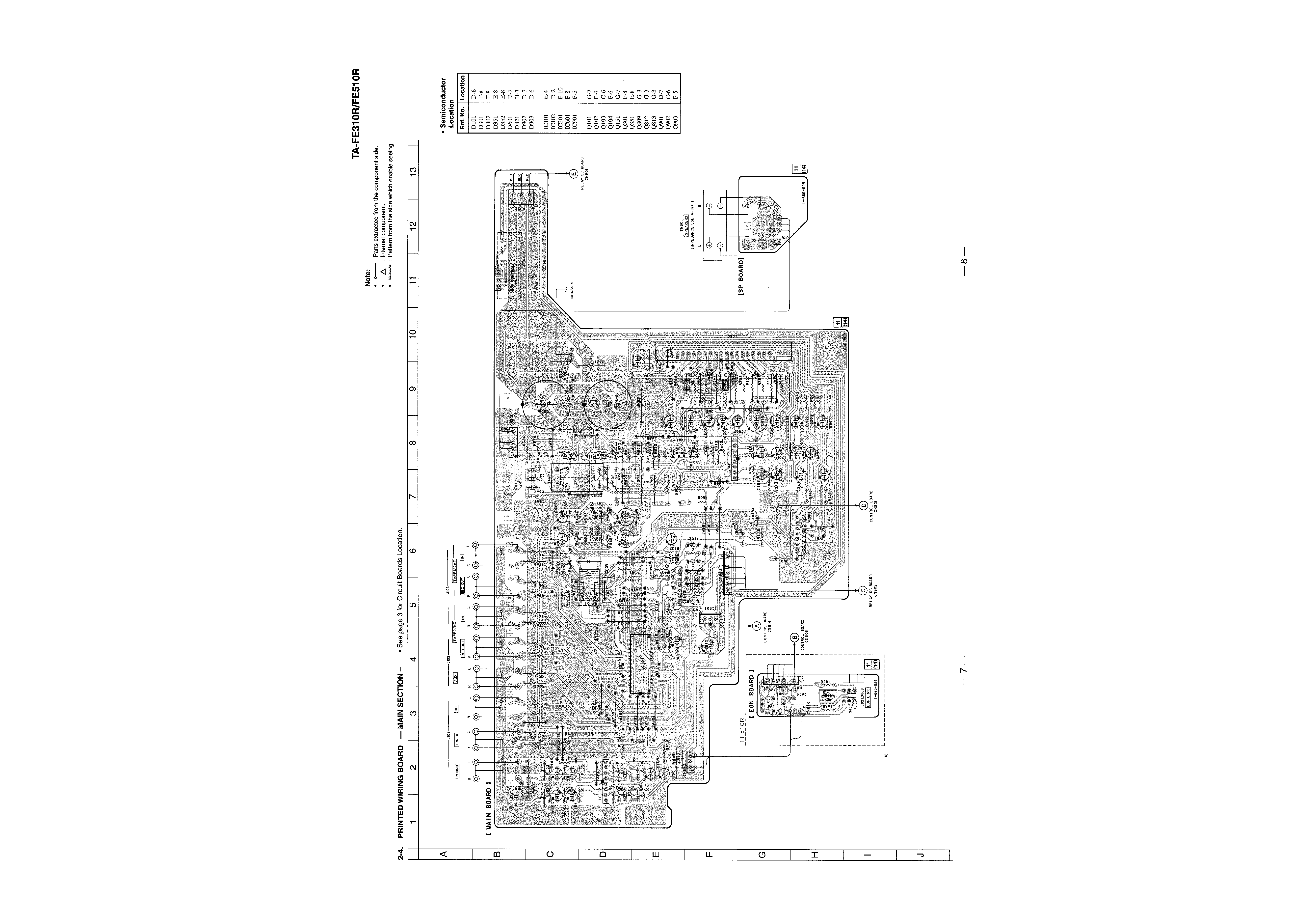
2-4.
Printed Wiring Boards -- Main Section -- ........................ 7
2-5.
Schematic Diagram -- Panel Section -- ............................ 9
2-6.
Printed Wiring Boards -- Panel Section -- ..................... 11
2-7.
Schematic Diagram -- Power Section -- ........................ 13
3.
EXPLODED VIEWS ................................................. 15
4.
ELECTRICAL PARTS LIST ................................. 17
SAFETY-RELATED COMPONENT WARNING!!
COMPONENTS IDENTIFIED BY MARK
! OR DOTTED LINE
WITH MARK
! ON THE SCHEMATIC DIAGRAMS AND IN
THE PARTS LIST ARE CRITICAL TO SAFE OPERATION.
REPLACE THESE COMPONENTS WITH SONY PARTS WHOSE
PART NUMBERS APPEAR AS SHOWN IN THIS MANUAL OR
IN SUPPLEMENTS PUBLISHED BY SONY.
SECTION 1
GENERAL
1-1.
INDEX TO PARTS AND CONTROLS
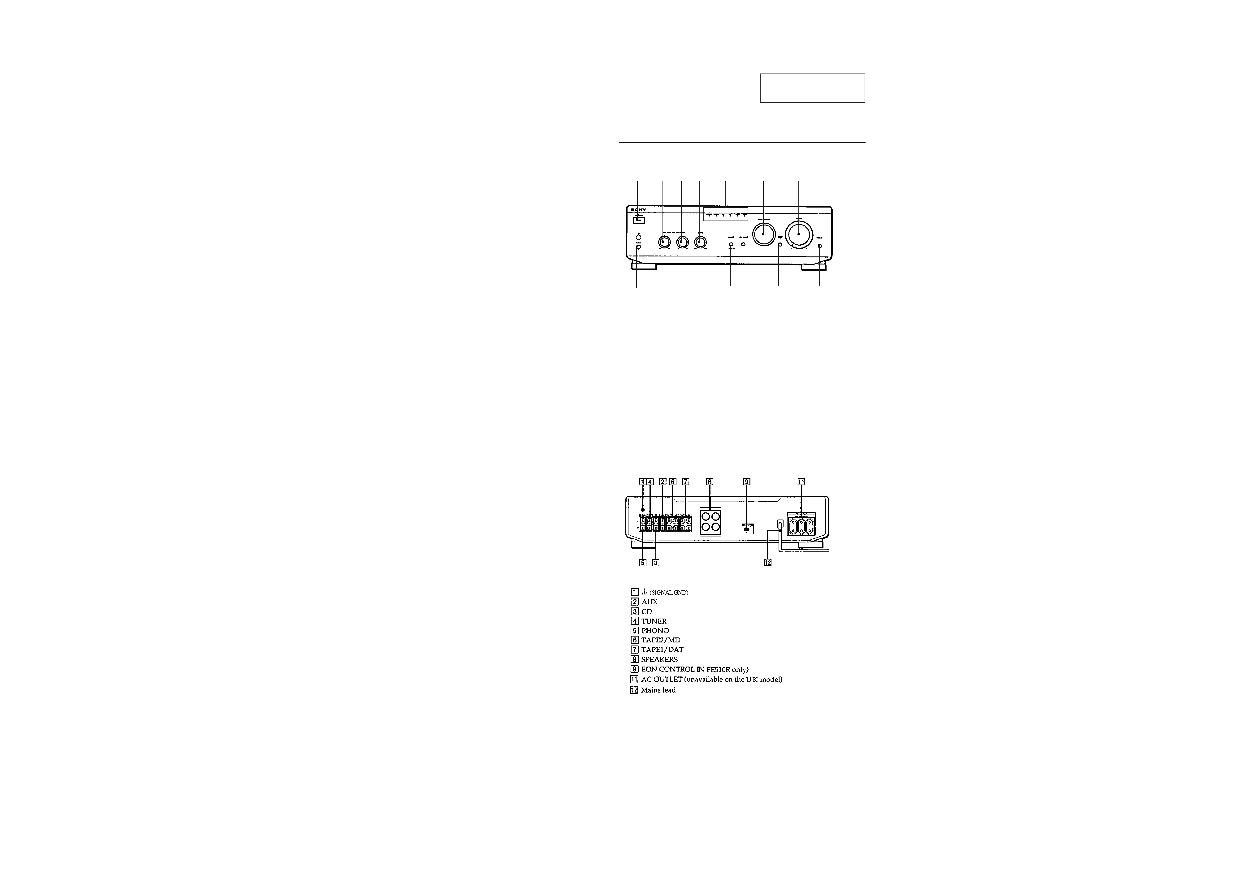
Front Panel
Rear Panel
12
3
4
5
6
7
!TM
!¡
0
9
8
1 SYSTEM POWER switch
2 BASS control
3 TREBLE control
4 BALANCE control
5 INPUT SELECTOR indicators
6 INPUT SELECTOR
7 VOLUME control
8 PHONES jack
9 LOUDNESS switch
!º TAPE 1 MONITOR switch (TA-FE510R only)
!¡ SOURCE DIRECT switch
!TM EON LINK switch (TA-FE510R only)
This section is extracted
from instruction manual.
TABLE OF CONTENTS
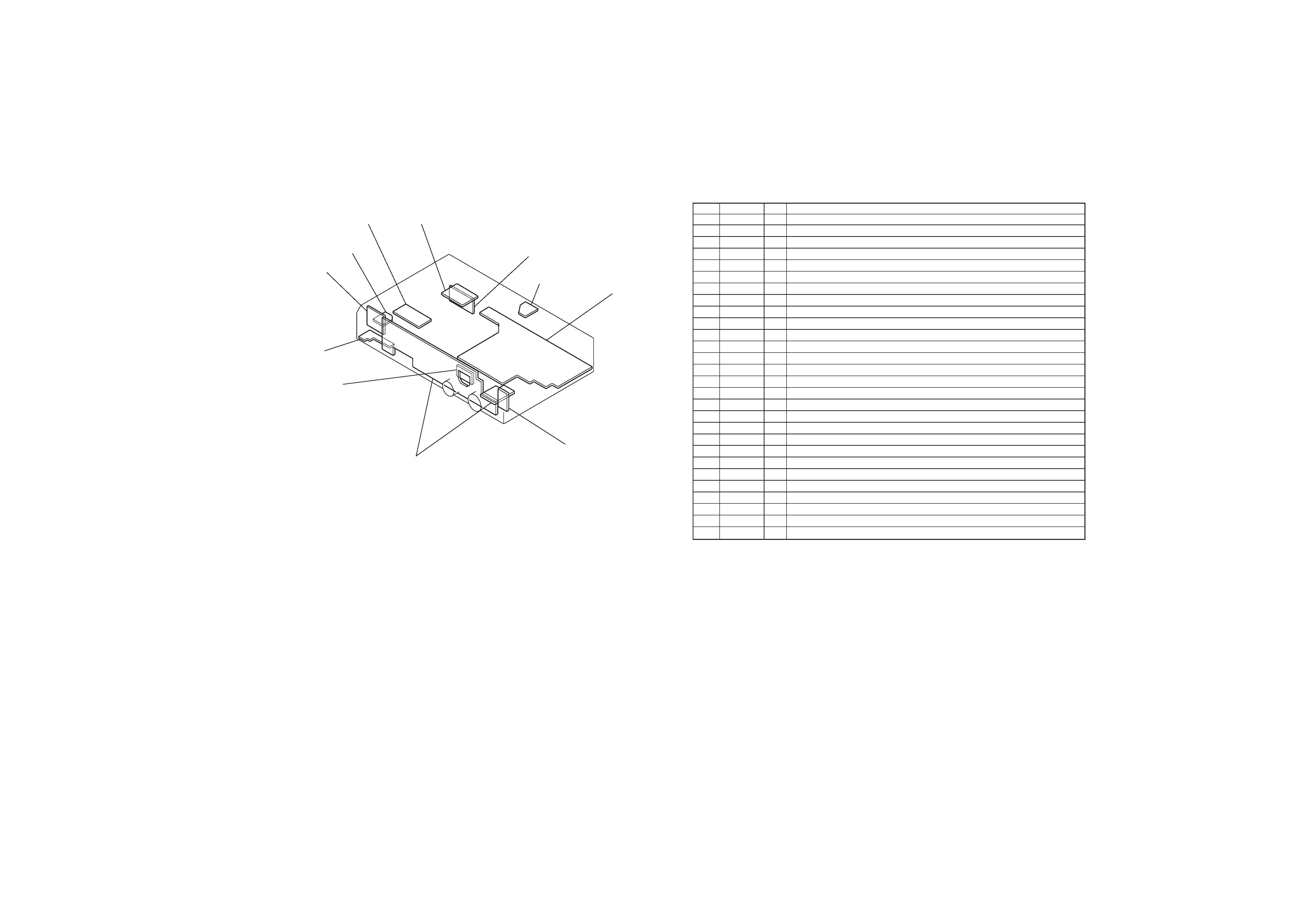
SECTION 2
DIAGRAMS
2-1.
CIRCUIT BOARDS LOCATION
RELAY AC board
SIRCS board
HP board
FUNCTION SW board
CONTROL board
EON board
(FE510R)
MAIN board
AC board (AEP, Germany)
SP board
AC SW board
RELAY DC board
2-2.
IC PIN FUNCTION DESCRIPTION
CONTROL BOARD IC801 TMP47C103N (INPUT CONTROL, LED DRIVE)
Pin No.
Pin Name
I/O
Function
1
X OUT
O
System clock. (4 MHz)
2
X IN
I
System clock. (4 MHz)
3
RESET
I
RESET input.
4
PMD
I
MODE select input.
5
VOL+
O
Motor drive output (+).
6
VOL
O
Motor drive output ().
7
SW0
I
Rotary switch input (CD).
8
SW1
I
Rotary switch input (TUNER).
9
SW2
I
Rotary switch input (PHONO).
10
EON
I
EON signal input.
11
PHONO
O
PHONO LED drive output.
12
TUNER
O
TUNER LED drive output.
13
CD
O
CD LED drive output.
14
GND
Ground.
15
AUX
O
AUX LED drive output.
16
DAT
O
TAPE "Z" LED drive output.
17
TAPE
O
TAPE "1" LED drive output.
18
MON
O
MONITOR output.
19
PRY
O
Power relay output.
20
PKY
I
Power key input.
21
MON
I
MONITOR input.
22
SIRCS
I
SIRCS input.
23
MUTE
O
Muting output.
24
SCE
O
Chip enable output.
25
SDT
O
Serial data output.
26
SCK
O
Serial clock output.
27
STOP
I
Stop input.
28
+3 V
+3 V power supply.
-- 3 --
-- 4 --