MICROFILM
SERVICE MANUAL
INTEGRATED STEREO AMPLIFIER
AEP Model
UK Model
TA-EX880
E Model
Tourist Model
TA-MS717
SPECIFICATIONS
TA-EX880/MS717
TA-EX880/MS717 are the amplifier section
in DHC-EX880MD/MD717.
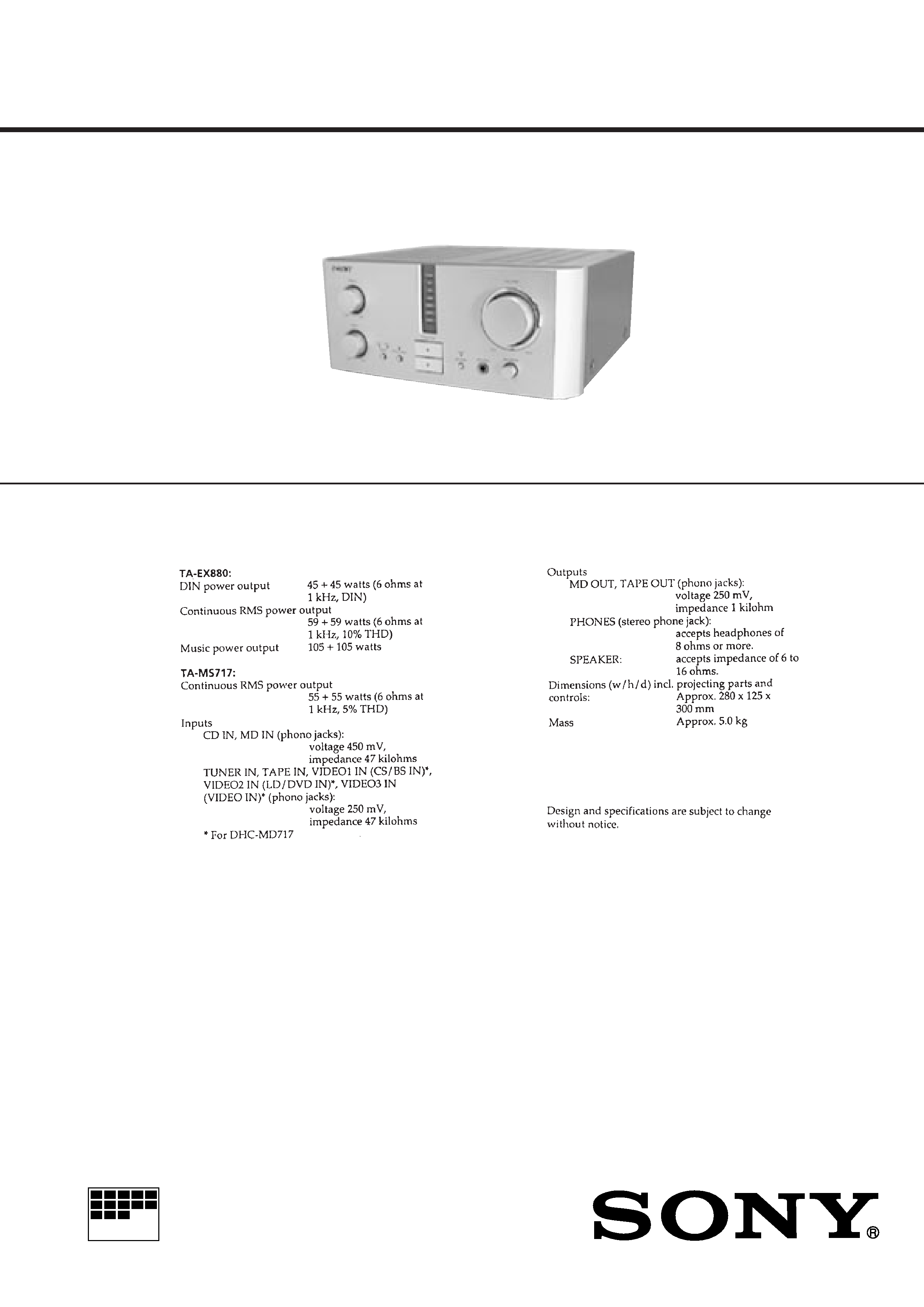
Photo: TA-MS717
2
TABLE OF CONTENTS
1.
SERVICING NOTES ................................................ 2
2.
GENERAL ................................................................... 3
3.
DISASSEMBLY ......................................................... 4
4.
DIAGRAMS
4-1. Printed Wiring Boards MAIN/POWER Section ..... 7
4-2. Schematic Diagram MAIN/POWER Section ........... 9
4-3. Schematic Diagram PANEL Section ....................... 12
4-4. Printed Wiring Boards PANEL Section .................. 15
4-5. IC Pin Function Description ........................................... 17
5.
EXPLODED VIEWS ................................................ 19
6.
ELECTRICAL PARTS LIST ............................... 21
SAFETY-RELATED COMPONENT WARNING!!
COMPONENTS IDENTIFIED BY MARK
! OR DOTTED
LINE WITH MARK
! ON THE SCHEMATIC DIAGRAMS
AND IN THE PARTS LIST ARE CRITICAL TO SAFE
OPERATION. REPLACE THESE COMPONENTS WITH
SONY PARTS WHOSE PART NUMBERS APPEAR AS
SHOWN IN THIS MANUAL OR IN SUPPLEMENTS PUB-
LISHED BY SONY.
SECTION 1
SERVICING NOTES
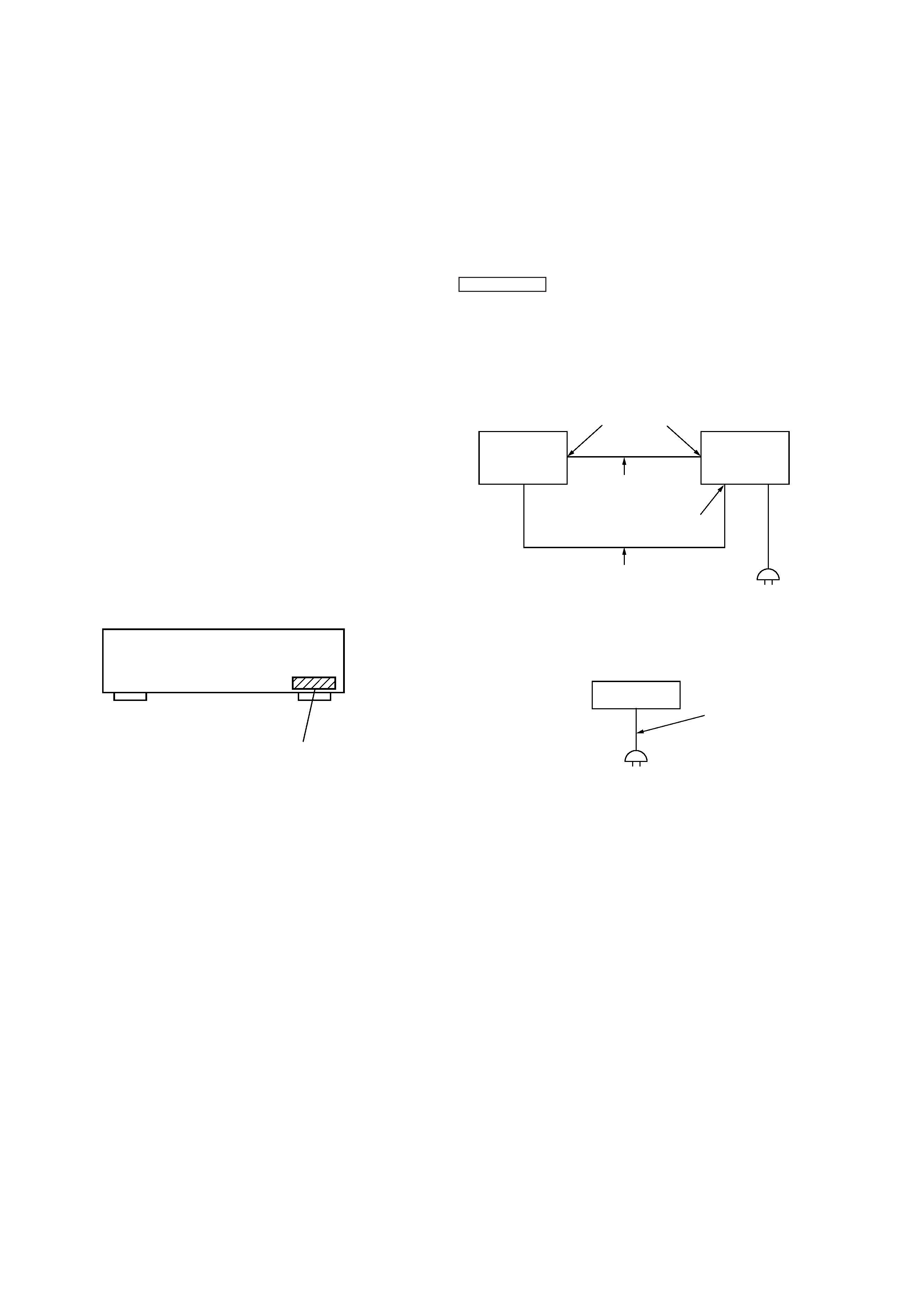
POWER ON/OFF CONTROL
· As the power on/off control is made by the Tuner Unit (ST-
EX880/MS717), the POWER switch is not provided to this set.
Accordingly, for servicing, connect the set to the Tuner Unit
(ST-EX880/MS717). (Fig. 1)
(If the Tuner Unit (ST-EX880/MS717) is not available, connect
a power cord directly to this set. (Fig. 2)
Also, if the set is not connected to the Tuner Unit (ST-EX880/
MS717), to enter the TEST mode (LED CHECK mode), press
FUNCTION
v button and [SOURCE DIRECT] button simul-
taneously two times.
When each button is pressed, the LED associated with each but-
ton lights up.
Connection:
Set
Tuner Unit
(ST-EX880/
MS717)
AC IN
Connector cable
(17P)
AC IN
terminal
Power cord attached to this set
SYSTEM CONTROL
terminal
Fig. 1
Fig. 2
Set
AC IN
Power cord
4-995-104-1: AEP, UK
4-995-104-2: Hong Kong, Singapore, Malaysia
4-995-104-3: Tourist
MODEL IDENTIFICATION
Back panel
3
SECTION 2
GENERAL
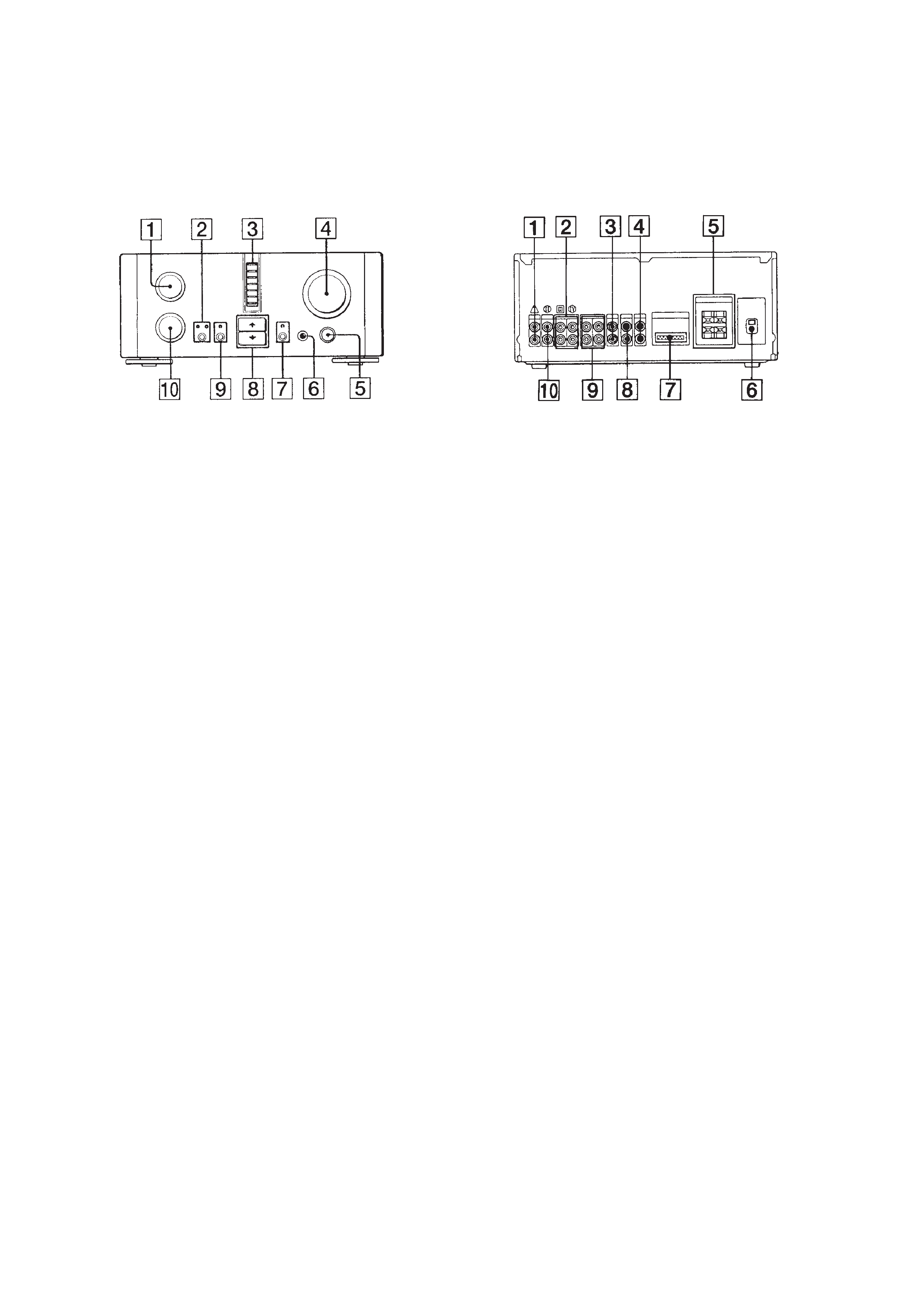
· LOCATION OF CONTROLS
Front Panel
1 TREBLE control knob
2 DBFB button, LOW/HIGH indicator
3 FUNCTION (TUNER, CD, MD, TAPE, CS/BS, LD/DVD,
VIDEO) indicator (TA-MS717)
FUNCTION (TUNER, CD, MD, TAPE, VIDEO1, VIDEO2,
VIDEO3) indicator (TA-EX880)
4 VOLUME control knob
5 BALANCE control knob
6 PNONES jack
7 20dB MUTING button and indicator
8 FUNCTION >/. button
9 SOURCE DIRECT button and indicator
0 BASS control knob
1 TUNER IN jack
2 MD IN/OUT jack
3 CS/BS IN jack (TA-MS717)
VIDEO1 IN jack (TA-EX880)
4 VIDEO IN jack (TA-MS717)
VIDEO3 IN jack (TA-EX880)
5 SPEAKER terminal
6 Power cord
7 SYSTEM CONTROL terminal
8 LD/DVD IN jack (TA-MS717)
VIDEO2 IN jack (TA-EX880)
9 TAPE IN/OUT jack
0 CD IN jack
Rear Panel
4
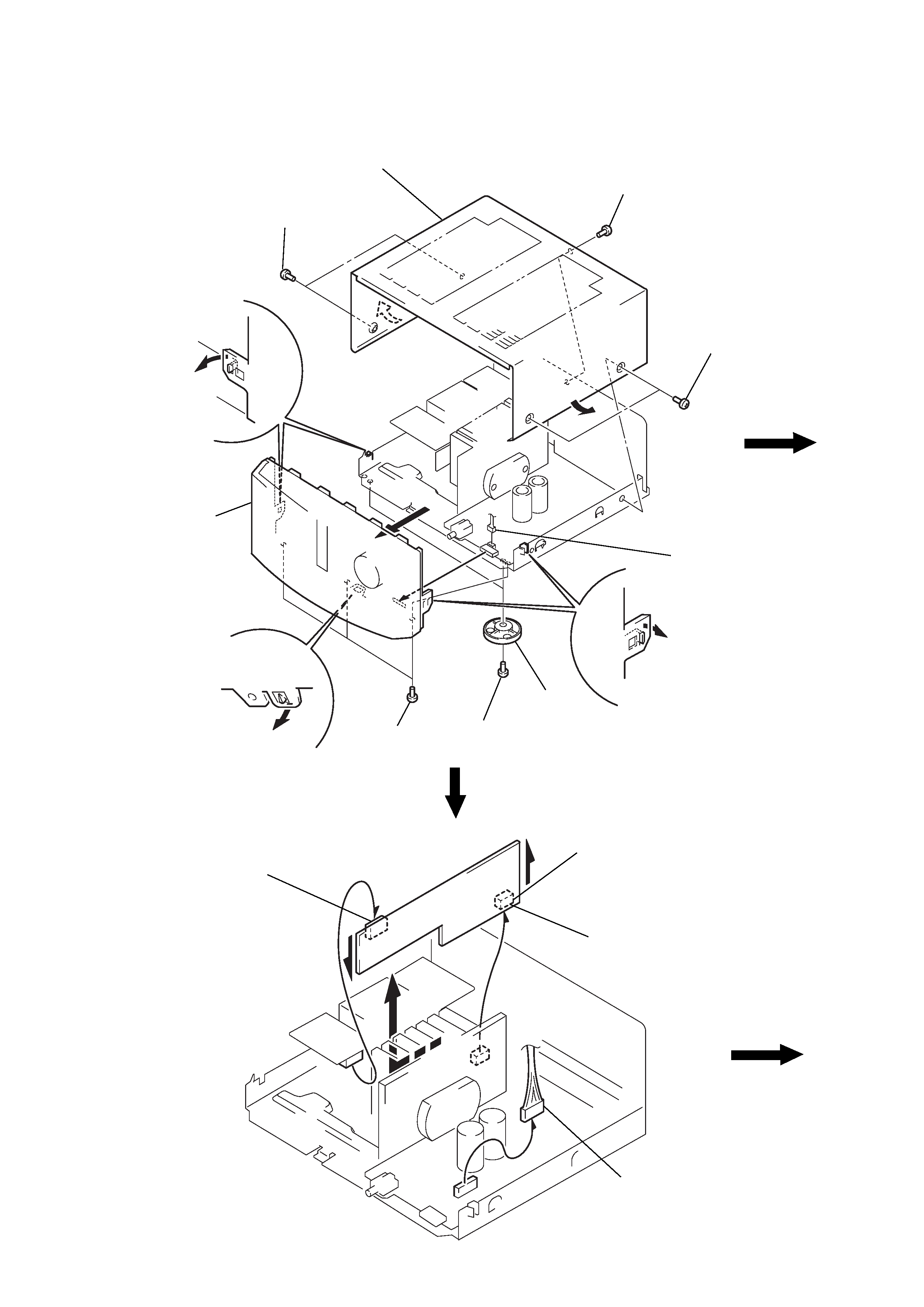
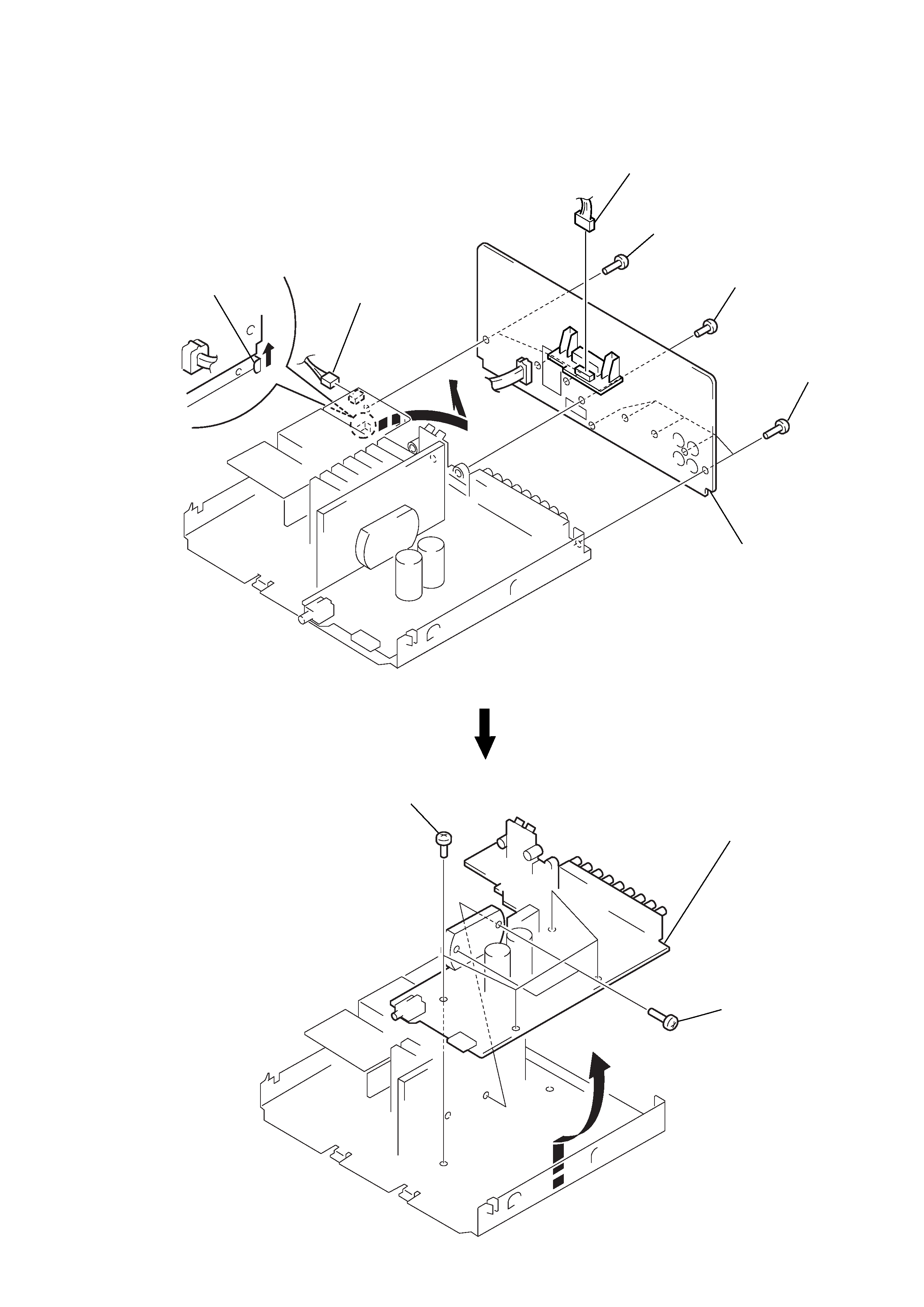
Note: Follow the disassembly procedure in the numerical order given.
SECTION 3
DISASSEMBLY
CASE, FRONT PANEL ASS'Y
CONNECTOR BOARD
1 screw
(BVTT3
× 6)
2 two crews
(case 3 TP2)
2 two screws
(case 3 TP2)
3 case
5 two screws
(BV3
× 10)
7 three screws
(BV3
× 10)
8 claw
8 two claws
6 two legs (F)
4 connector
(CN504)
9 front panel ass'y
8 two claws
2 Remove the
connector (CN553)
to direction of arrow A.
3 Remove the
connector (CN554)
to direction of arrow B.
4 Remove the
connector board
to direction of arrow C.
1 connector (CN501)
B
C
A
5
MAIN BOARD
BACK PANEL
4 claw
1 connector
(CN911)
1 connector
(CN601)
5 Remove the back
panel to direction
of arrow A.
3 screw
(BV3
× 8)
2 five screws
(BV3
× 10)
2 three screws
(BV3
× 10)
A
3 Remove the main board
to direction of arrow A.
1 two screws
(BV3
× 16)
2 four screws
(BVTT3
× 6)
A