
SERVICE MANUAL
Design and specifications are subject to change without notice.
DIGITAL NETWORK RECORDER
US Model
SVR-3000 RMT-V303
9-965-936-03
ORIGINAL MANUAL ISSUE DATE: 12/2002
ALL REVISIONS AND UPDATES TO THE ORIGINAL MANUAL ARE APPENDED TO THE END OF THE PDF FILE.
REVISION DATE
REVISION TYPE
SUBJECT
12/2002
No revisions or updates are applicable at this time.
12/2002
Correction-1
Added P/N for Battery Cover (Replaced Page 54)
1/2003
Correction-2
IC600 added to Electrical Parts List
HISTORY INFORMATION FOR THE FOLLOWING MANUAL:
SERVICE MANUAL
Design and specifications are subject to change without notice.
DIGITAL NETWORK RECORDER
US Model
SVR-3000 RMT-V303
SPECIFICATIONS
Self Diagnosis
Supported model
TM
Inputs and Outputs:
Video In:
S-Video 4-pin mini DIN (1)
Composite Video RCA (1)
Video Out: S-Video 4-pin mini DIN (2)
Composite Video RCA (2)
Audio Line In:Stereo L/R RCA (1 pair)
Audio Line Out: Stereo L/R RCA (2 pairs)
RF In: F-Connector Female (1)
RF Out: F-Connector Female (1)
Telephone: RJ-11 Female, 2 wire (1)
Control Out: 3.5 mm Mini Jack Sockets (2)
General: Accessories:
Power Requirements: 120 V AC, 60 Hz
Power Consumption: 29 W
Operating Temperature: 21°C to 45°C (70°F to 113°F)
Operating Humidity: 5% to 80%
Dimensions: Approx. 430 x 77 x 326 mm (w/h/d)
Approx. 171/4 x 37/8 x 121/8 (w/h/d)
(including projecting parts and controls)
Mass: Approx. 4.5 kg (9 lbs. 1 oz.)
Supplied Accessories:
Remote Control (1)
Size AA (R6) Batteries (2)
Audio/Video Cable (1)
IR Control Cable (two IR emitters) (2)
Serial Control Cable (1)
S-Video Cable (1)
Phone Cord (1)
Phone Splitter (1)
SVR-3000
RMT-V303
9-965-936-03

-- 3 --
SVR-3000
SECTION TITLE
PAGE
TABLE OF CONTENTS
Warnings and Cautions..................................................................................................................... 4
Safety Check-Out.............................................................................................................................. 5
SECTION 1: DISASSEMBLY................................................................................................................................. 6
1-1. Top Cover Removal ........................................................................................................................... 6
1-2. Hard Disk and D.C. Fan Removal ..................................................................................................... 6
1-3. MA-411 Board and PS-445 Board Removal...................................................................................... 7
1-4. Front Panel Assembly Removal......................................................................................................... 7
1-5. Front Frame Removal........................................................................................................................ 8
1-6. FL-127 Board and FR-188 Board Removal....................................................................................... 8
1-7. Service Position................................................................................................................................. 9
SECTION 2: DIAGRAMS..................................................................................................................................... 10
2-1. Circuit Boards Location.................................................................................................................... 10
2-2. Printed Wiring Board and Schematic Diagram Information ............................................................. 10
2-3. Block Diagram ..................................................................................................................................11
2-4. Schematic Diagrams and Supporting Information ........................................................................... 12
System Power ................................................................................................................................. 12
System Clock & Reset for MA PWB 1-686-359-12 ......................................................................... 13
System Clock & Reset for MA PWB 1-686-359-13 ......................................................................... 14
NTSC Video Decoder...................................................................................................................... 15
Tuner/MTS Stereo Decode & ADC.................................................................................................. 16
A/V Encoder SDRAM ...................................................................................................................... 17
MIPS CPU....................................................................................................................................... 18
Host Ctl, XPort, MPEG Decoder .................................................................................................... 19
System Memory .............................................................................................................................. 20
Media Switch ASIC.......................................................................................................................... 21
Flash/Therm Mgmt/RTC.................................................................................................................. 22
IDE Interface for MA Board with IC 1000 ........................................................................................ 23
IDE Interface for MA Board with IC 1002 ........................................................................................ 24
Modem Chipset ............................................................................................................................... 25
Modem DAA.................................................................................................................................... 26
USB Host Control............................................................................................................................ 27
NTSC Video Encoder...................................................................................................................... 28
IR Cont ............................................................................................................................................ 29
@Eshe ............................................................................................................................................ 29
PS-449 Board Schematic Diagram ................................................................................................. 32
FL-127 Board Schematic Diagram.................................................................................................. 34
FR-134 Board Schematic Diagram ................................................................................................. 36
SECTION 3: EXPLODED VIEWS........................................................................................................................ 38
3-1. Chassis............................................................................................................................................ 38
SECTION 4: ELECTRICAL PARTS LIST............................................................................................................ 39

-- 4 --
SVR-3000
WARNINGS AND CAUTIONS
CAUTION
Short circuit the anode of the picture tube and the anode cap to the metal chassis, CRT shield, or carbon painted on the CRT, after
removing the anode.
WARNING!!
An isolation transformer should be used during any service to avoid possible shock hazard, because of live chassis. The chassis of this
receiver is directly connected to the ac power line.
! SAFETY-RELATED COMPONENT WARNING!!
Components identified by shading and ! mark on the schematic diagrams, exploded views, and in the parts list are critical for safe
operation. Replace these components with Sony parts whose part numbers appear as shown in this manual or in supplements published
by Sony. Circuit adjustments that are critical for safe operation are identified in this manual. Follow these procedures whenever critical
components are replaced or improper operation is suspected.
ATTENTION!!
Apres avoir deconnecte le cap de l'anode, court-circuiter l'anode du tube cathodique et celui de l'anode du cap au chassis metallique de
l'appareil, ou la couche de carbone peinte sur le tube cathodique ou au blindage du tube cathodique.
Afin d'eviter tout risque d'electrocution provenant d'un chássis sous tension, un transformateur d'isolement doit etre utilisé lors de tout
dépannage. Le chássis de ce récepteur est directement raccordé à l'alimentation du secteur.
! ATTENTION AUX COMPOSANTS RELATIFS A LA SECURITE!!
Les composants identifies par une trame et par une marque ! sur les schemas de principe, les vues explosees et les listes de pieces
sont d'une importance critique pour la securite du fonctionnement. Ne les remplacer que par des composants Sony dont le numero de
piece est indique dans le present manuel ou dans des supplements publies par Sony. Les reglages de circuit dont l'importance est
critique pour la securite du fonctionnement sont identifies dans le present manuel. Suivre ces procedures lors de chaque remplacement
de composants critiques, ou lorsqu'un mauvais fonctionnement suspecte.
-- 5 --
SVR-3000
SAFETY CHECK-OUT
After correcting the original service problem, perform the following
safety checks before releasing the set to the customer:
1. Check the area of your repair for unsoldered or poorly soldered
connections. Check the entire board surface for solder splashes and
bridges.
2. Check the interboard wiring to ensure that no wires are "pinched" or
touching high-wattage resistors.
3. Check that all control knobs, shields, covers, ground straps, and
mounting hardware have been replaced. Be absolutely certain that
you have replaced all the insulators.
4. Look for unauthorized replacement parts, particularly transistors,
that were installed during a previous repair. Point them out to the
customer and recommend their replacement.
5. Look for parts which, though functioning, show obvious signs of
deterioration. Point them out to the customer and recommend their
replacement.
6. Check the line cords for cracks and abrasion. Recommend the
replacement of any such line cord to the customer.
7. Check the B+ and HV to see if they are specified values. Make
sure your instruments are accurate; be suspicious of your HV
meter if sets always have low HV.
8. Check the antenna terminals, metal trim, "metallized" knobs,
screws, and all other exposed metal parts for AC leakage. Check
leakage as described below.
Leakage Test
The AC leakage from any exposed metal part to earth ground and from
all exposed metal parts to any exposed metal part having a return to
chassis, must not exceed 0.5 mA (500 microamperes). Leakage current
can be measured by any one of three methods.
1. A commercial leakage tester, such as the Simpson 229 or RCA
WT-540A. Follow the manufacturers' instructions to use these
instructions.
2. A battery-operated AC milliampmeter. The Data Precision 245
digital multimeter is suitable for this job.
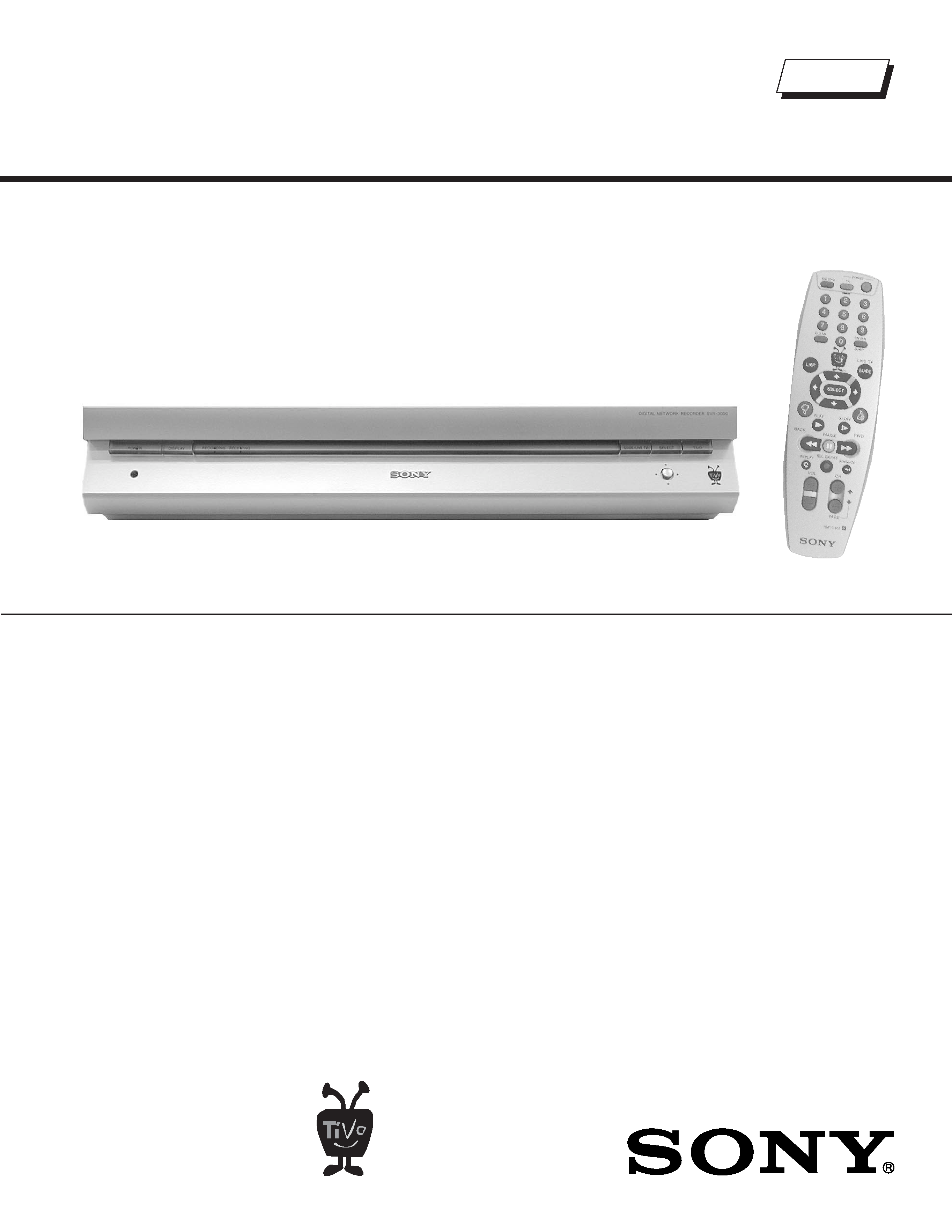
3. Measuring the voltage drop across a resistor by means of a VOM
or battery-operated AC voltmeter. The "limit" indication is 0.75
V, so analog meters must have an accurate low voltage scale.
The Simpson's 250 and Sanwa SH-63TRD are examples of
passive VOMs that are suitable. Nearly all battery-operated digital
multimeters that have a 2 VAC range are suitable (see Figure A).
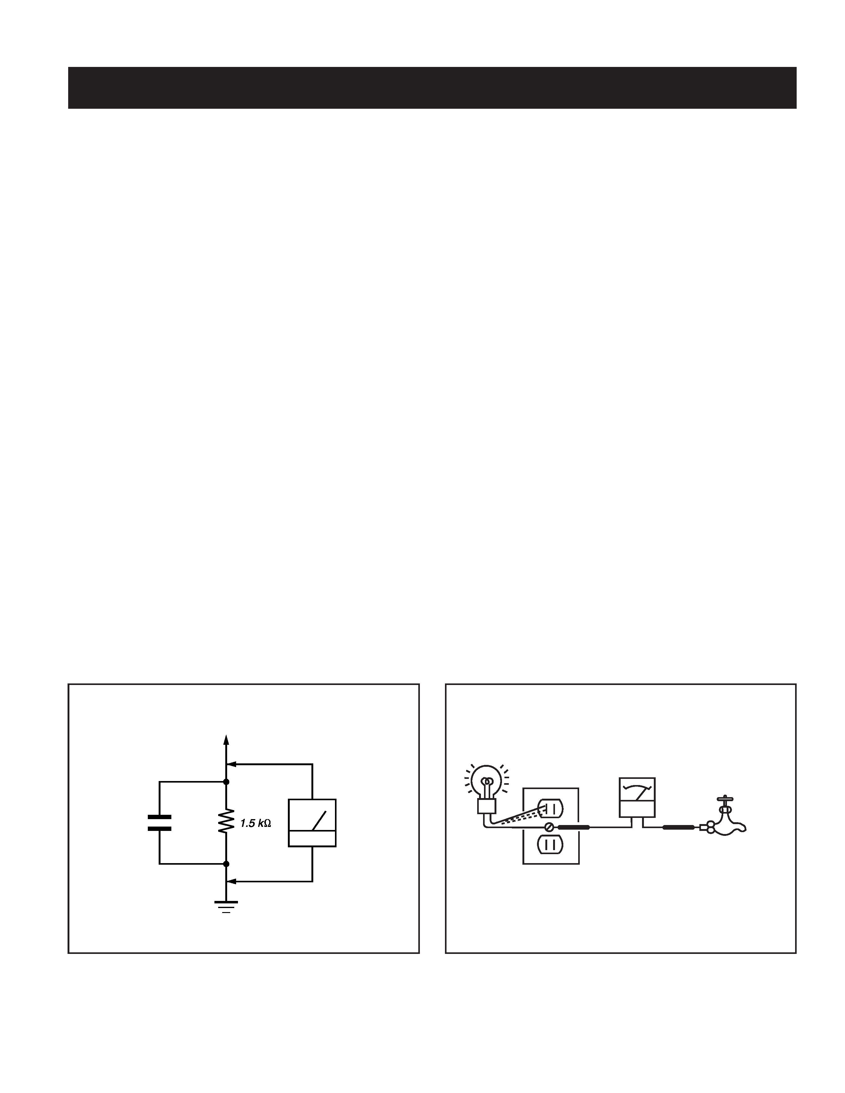
How to Find a Good Earth Ground
Acold-water pipe is a guaranteed earth ground; the cover-plate retaining
screw on most AC outlet boxes is also at earth ground. If the retaining
screw is to be used as your earth ground, verify that it is at ground
by measuring the resistance between it and a cold-water pipe with an
ohmmeter. The reading should be zero ohms.
If a cold-water pipe is not accessible, connect a 60- to 100-watt trouble-
light (not a neon lamp) between the hot side of the receptacle and the
retaining screw. Try both slots, if necessary, to locate the hot side on the
line; the lamp should light at normal brilliance if the screw is at ground
potential (see Figure B).
Trouble Light
AC Outlet Box
Ohmmeter
Cold-water Pipe
Figure A. Using an AC voltmeter to check AC leakage.
Figure B. Checking for earth ground.
To Exposed Metal
Parts on Set
0.15 µF
Earth Ground
AC
Voltmeter
(0.75V)