HISTORY
Model Name: SU-GW12
SERVICE MANUAL
Part No. : 9-872-725-02
When clicking an item, it's detail is displayed.
Date
Version No.
Description of SUP/COR
Change of
main text
2004.06
1.0
NEW
2004.11
2.0
Addition of World model
SERVICE MANUAL
MODEL
COMMANDER DEST.
CHASSIS NO.
TV STAND
SU-GW12
US, CND
SU-GW12
WORLD
2
SU-GW12
SECTION 1
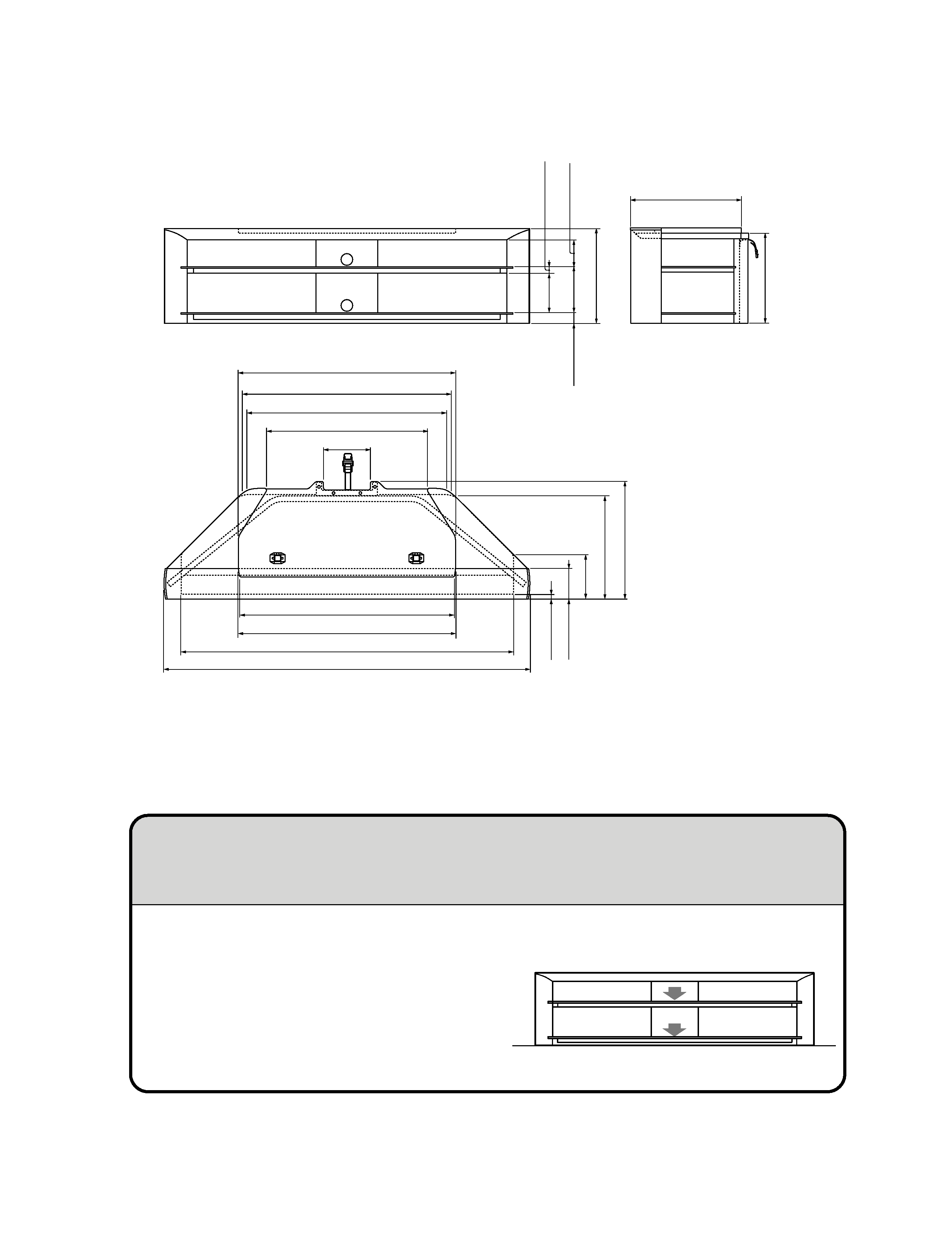
SPECIFICATIONS
Design and specifications are subject to change without notice.
La conception et les spécifications sont sujettes à modifications sans préavis.
Diseño y especificaciones sujetos a cambios sin previo aviso.
956.6 (37 3/4)
923.4 (36 3/8)
740.7 (29 1/4)
220 (8 3/4)
1,000.6 (39 1/2)
48.1
(1
15
/16
)
181.5
(7
1 /
4)
125
(5)
440
(17
3 /
8)
508.5 (20 1/8)
483.8
(19
1 /
8)
543.8
(21
1 /
2)
212.9
(8
1 /
2)
141.5
(5
5 /
8)
31.4
(1
1 /
4)
415
(16
3 /
8)
990.9 (39 1/8)
1,530 (60 3/8)
1,002.6 (39 1/2)
1,688.2 (66 1/2)
18.3
(
3 /
4)
199
(7
7 /
8)
Dimensions Unit: mm (inch)
Weight: 52.5 kg (115 lb 11 7/8 oz)
Dimensions en : mm (pouce)
Poids : 52,5 kg (115 lb 11 7/8 oz)
Unidad de dimensión: mm (pulgada)
Peso: 52,5 kg (115 lb 11 7/8 oz)
Do not place any equipment which exceeds the maximum
weight for each shelf as indicated in the illustration. Otherwise,
the shelf may break.
Ne placez aucun appareil dont le poids dépasse la capacité de
charge maximale indiquée sur l'illustration pour chaque étagère.
Sinon, celle-ci risque de se briser.
No coloque sobre los estantes ningún equipo que supere el peso
máximo permitido para cada uno según se indica en la
ilustración. Si lo hace, el estante puede romperse.
Note on carrying capacity
Remarque sur la capacité de charge
Nota sobre la capacidad de carga
60 kg (132 lb 5 oz)
20 kg (44 lb 1 oz)
30 kg (66 lb 2 oz)
3
SU-GW12
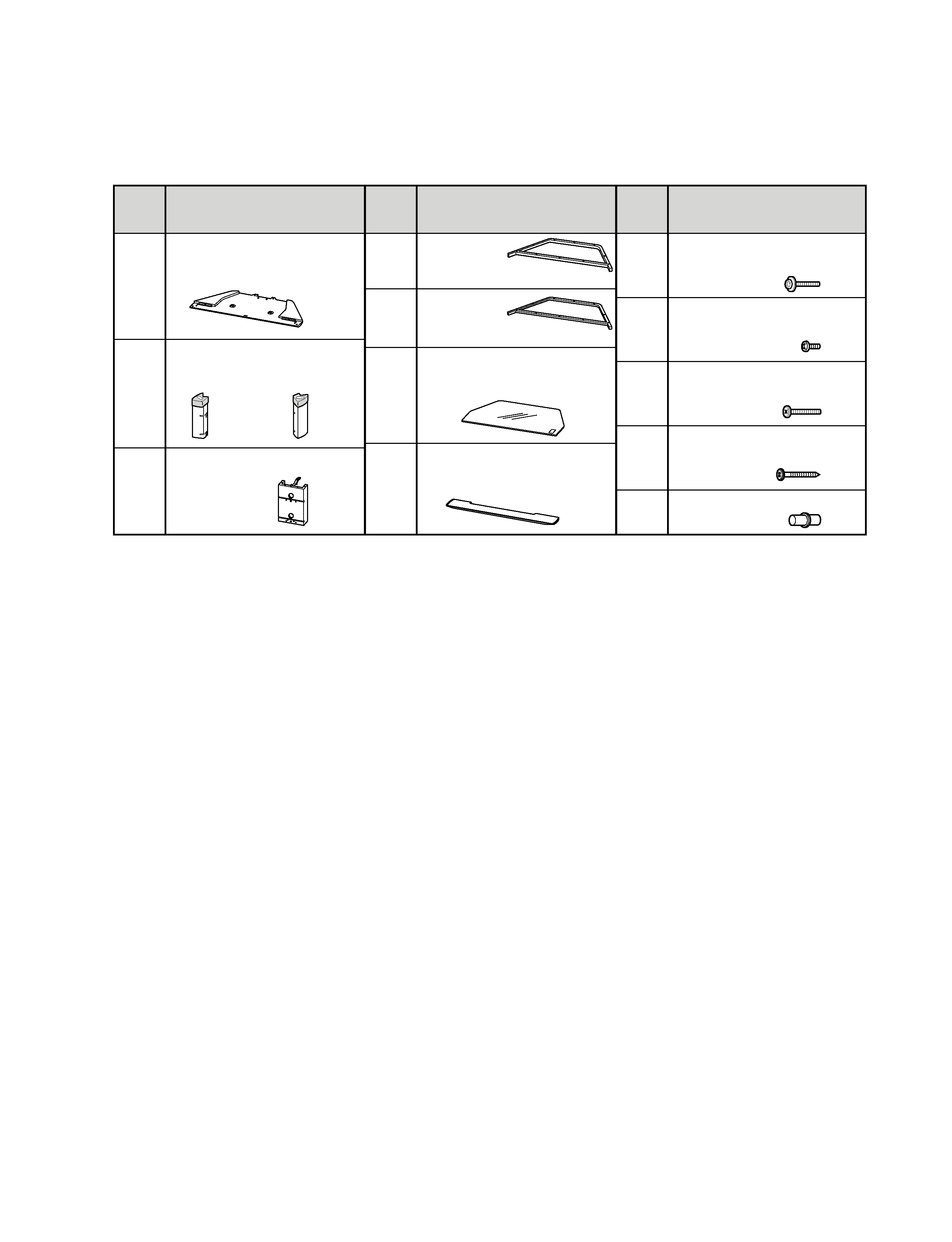
Symbol
Parts name
× Number of Parts
Symbole Nom des pièces
× quantité
Símbolo Nombre de la pieza x número de piezas
Top panel
Panneau supérieur
Panel superior
A
× 1
Side panel (
B)
Side panel (
C)
Panneau latéral (
B) Panneau latéral (C)
Panel lateral (
B) Panel lateral (C)
B
C
× 1
× 1
Rear panel
Panneau arrière
Panel posterior
D
× 1
Symbol
Parts name
× Number of Parts
Symbole Nom des pièces
× quantité
Símbolo Nombre de la pieza x número de piezas
Bottom frame
E
Partie inférieure
du châssis
Marco inferior
× 1
Middle frame
F
Partie médiane
du châssis
Marco central
× 1
Glass shelf
Etagère en verre
Estante de cristal
G
× 2
Top front cover
Couvercle avant supérieur
Cubierta frontal superior
H
× 1
Symbol
Parts name
× Number of Parts
Symbole Nom des pièces
× quantité
Símbolo Nombre de la pieza x número de piezas
Screw M5 x 25 mm
I
Vis M5 X 25 mm
Tornillo M5 X 25 mm
× 6
Screw M5 x 10 mm
J
Vis M5 X 10 mm
Tornillo M5 X 10 mm
× 6
Screw M6 x 40 mm
Vis M6 X 40 mm
K
Tornillo M6 X 40 mm
× 6
Screw 6 x 50 mm
Vis 6 X 50 mm
L
Tornillo 6 X 50 mm
× 4
Plug
M
Cheville
Conector
× 2
·Prepare a Phillips screwdriver before assembling the stand.
·Préparez un tourne-vis cruciforme avant de monter le meuble.
·Tenga listo un destornillador Phillips antes de armar la mesa.
4
SU-GW12
· Items marked " * " are not stocked since
they are seldom required for routine
service.
Some
delay
should
be
anticipated when ordering these items.
· Items with no part number and no
description are not stocked because they
are seldom required for routine service.
· The construction parts of an assembled
part are indicated with a collation number
in the remark column.
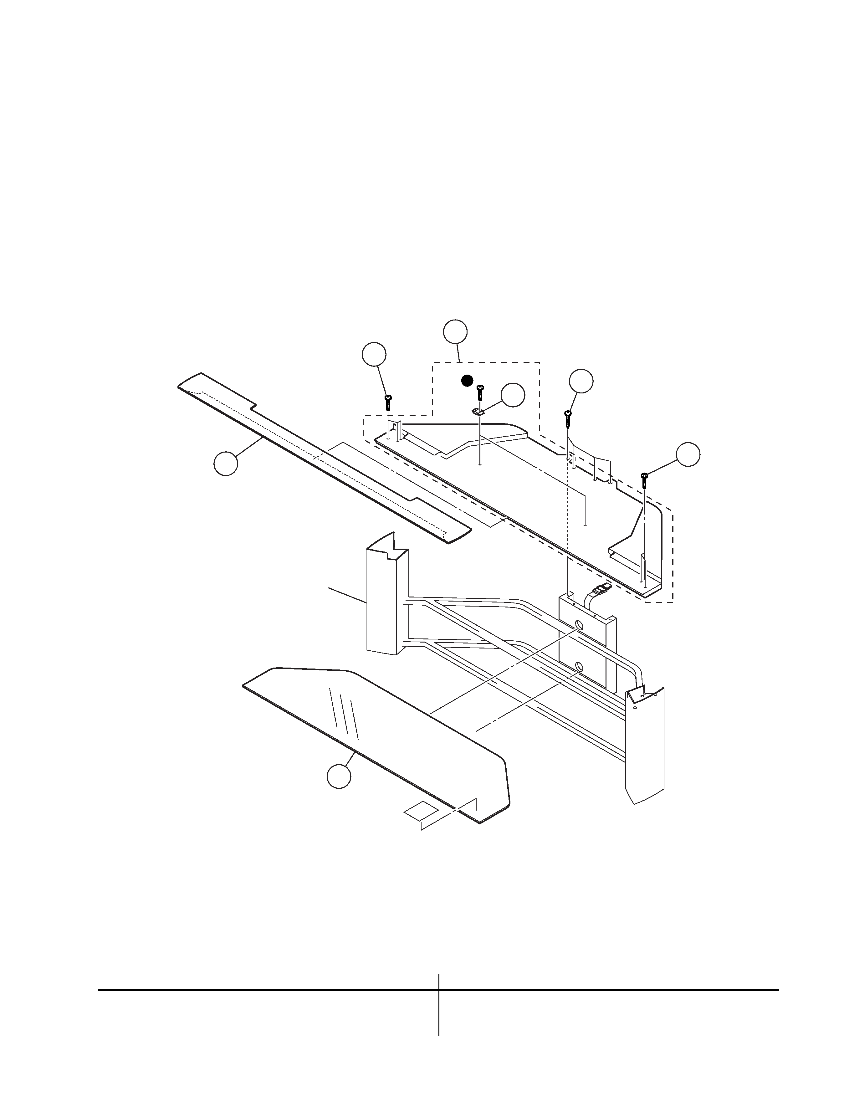
2-1. TOP PLATE BLOCK
z
: 7-685-663-79 SCREW +P 4X16
SECTION 2
EXPLODED VIEWS
NOTE:
REF.NO. PART NO.
DESCRIPTION
REMARK
REF.NO. PART NO.
DESCRIPTION
REMARK
1
2-149-159-01 GLASS SHELF
2
* X-2022-651-1 FRONT COVER ASSY
3
2-179-590-01 SCREW, SPECIAL (M6X40)
4
* X-2022-644-1 TOP BOARD ASSY
6
5
2-055-611-01 SCREW, SPECIAL (6X50)
6
4-064-939-01 STOPPER (B)
1
2
3
3
4
6
5
PILLAR BLOCK