TV STAND
SERVICE MANUAL
MODEL
SU-DR38G
2
SU-DR38G
A
B
C
D
E
F
G
N
KM
L
J
I
H
O
P
Q
NS
R
U
V
T
Dimension (cm)
A
B
C
D
E
F
G
H
I
J
K
L
M
N
O
P
Q
R
S
T
U
V
Weight (kg)
SU-DR38G
42.7
23.2
18.3
46.5
78.5
98.8
77.3
99.9
1.2
3.9
24.8
7.5
27.0
10.1
58.1
41.7
5.2
6.6
9.0
65.6
44.6
46.4
19.5
Design and specification are subject to change without notice.
SPECIFICATIONS

SU-DR38G
3
TABLE OF CONTENTS
1. DISASSEMBLY
1-1. Cap Removal ............................................................. 4
1-2. Holder Glass Removal .............................................. 4
1-3. Shelf Glass (Upper & Lower) Removal ................... 4
1-4. Frame Removal ......................................................... 4
1-5. Foot, Bottom Board Removal ................................... 4
1-6. Caster and Roller Removals ..................................... 4
1-7. Cover and Belt (DR) Hold Removals ....................... 5
2. EXPLODED VIEWS
2-1. Chassis ....................................................................... 6
OPERATING INSTRUCTIONS
Section
Title
Page
Section
Title
Page
4
SU-DR38G
Screw, M3 case
Caster (P)
Roller
Roller
Cover (s)
Bottom board
Shaft
(DIA. 5x27)
Shaft (DIA. 5x27)
Cover (s)
Assy, Foot (ER)
Assy, Foot
(DR-RS)
Assy, Foot
(DR-LS)
Assy, Bottom
Board
Screw, PWH + TP
Assy, Frame
Screw + TP
Washer Head 4 x 16
Shelf Glass
Shelf Glass
Assy, Frame
Cather (
×) Glass
Screw, PWH+TP
Cap (RS)
Cap (ER)
Cap (LS)
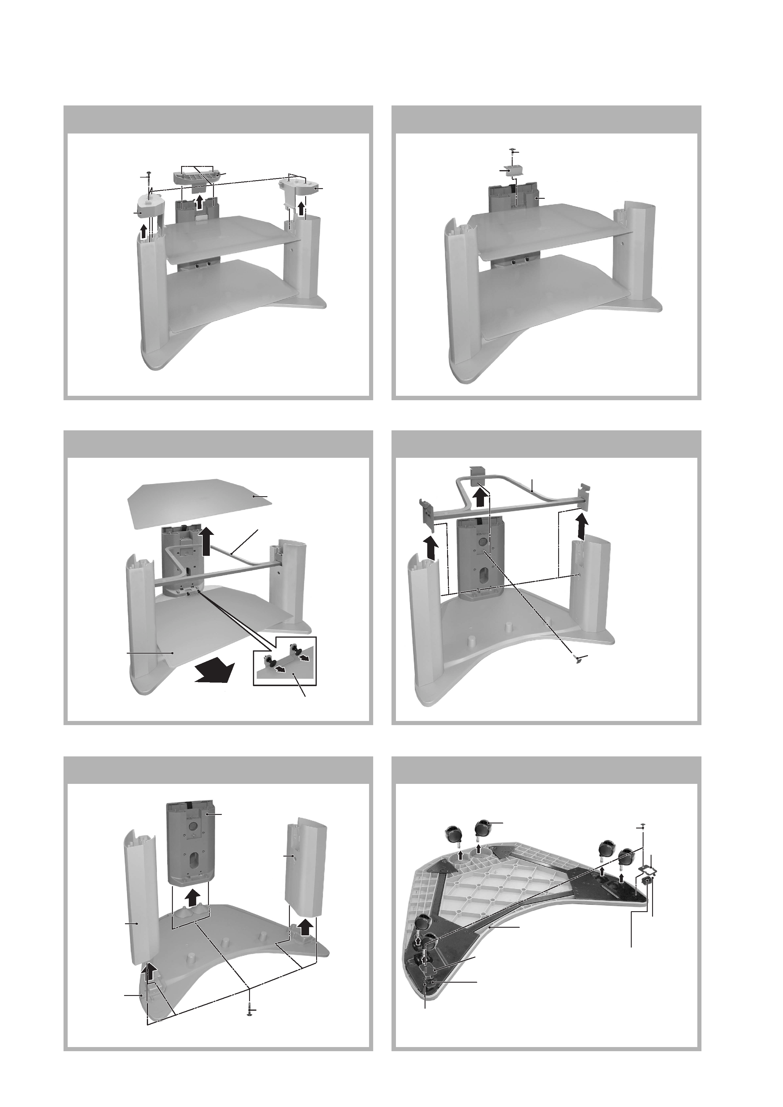
SECTION 1
DISASSEMBLY
1-1.
CAP REMOVAL
1-2.
HOLDER GLASS REMOVAL
1-3.
SHELF GLASS (UPPER & LOWER) REMOVAL
1-4.
FRAME REMOVAL
1-5.
FOOT, BOTTOM BOARD REMOVAL
Screw + TP
Washer Head 4 x 16
Assy, Foot (ER)
Holder glass
1-6.
CASTER AND ROLLER REMOVALS
5
SU-DR38G
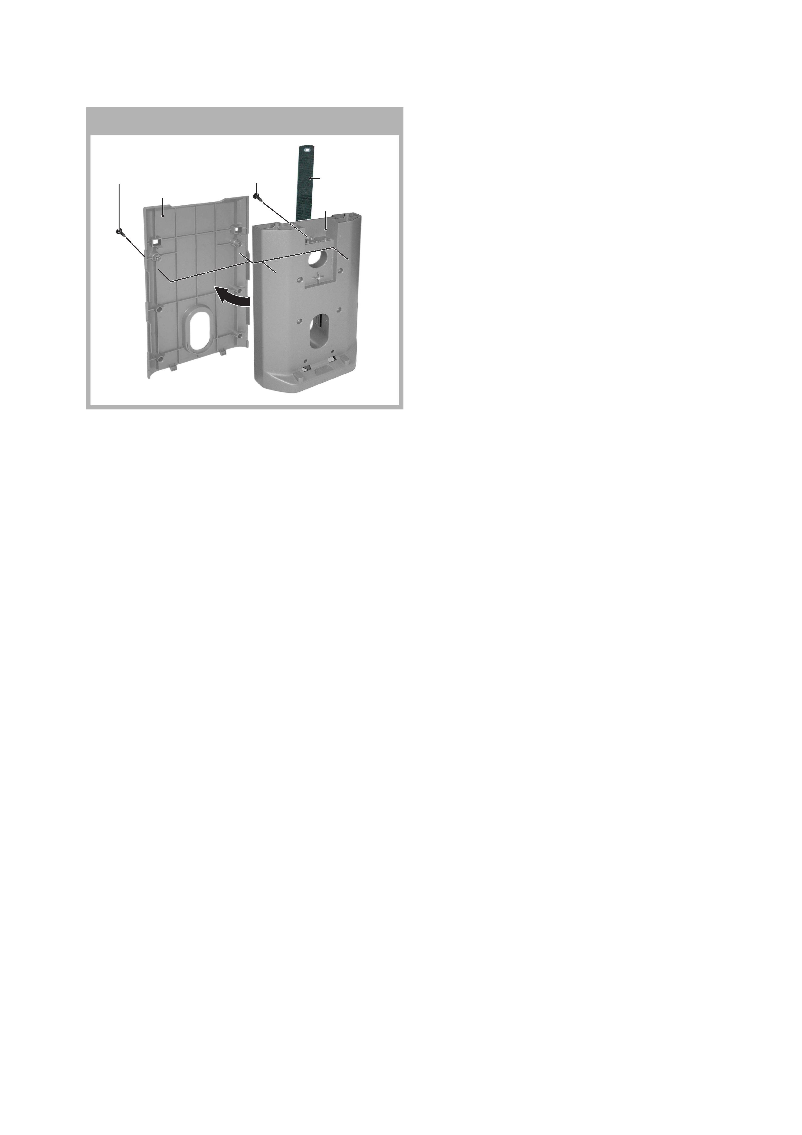
1-7.
COVER AND BELT (DR) HOLD REMOVALS
Cover (ER)
Screw +
BVTP 4 x 16
Screw +
BVTP 4 x 16
Belt (DR) Hold
Assy, Foot (ER)