INSTRUCTIONS
The SU-32FD4 TV stand is designed for use with the following
TV models (see below).
The SU-36FD4 TV stand is designed for use with the following
TV models (see below).
NOTES ON ASSEMBLY
G You will need a medium size Phillips head screwdriver.
G Assemble the stand only by the method shown in this
instruction sheet.
G Assemble the stand near the location where the stand
will be used.
G The circled letters in the illustrations are the same as
those in the "PARTS LIST". For easier assembly, line up
the parts in the order they will be required.
NOTES ON USE
G Do not place the stand in a location near a heat source,
such as a radiator, or in a place subject to direct
sunlight.
G Clean the stand periodically with a soft cloth.
If finger
prints, food and beverage stains, etc., are difficult to
remove, use a cloth moistened with a mild detergent
solution.
Do not use a scouring powder, abrasive pad
or solvent.
INSTRUCCIONES
El soporte de televisor SU-32FD4 esta diseñado para ser utilizado con
las siguientes modelos de televisor (ver a continuación).
El soporte de televisor SU-36FD4 esta diseñado para ser utilizado con
las siguientes modelos de televisor (ver a continuación).
NOTAS ACERCA DEL MONTAJE
G Usted necesitará un desarmador mediano de cruz.
G Ensamble el soporte de televisor siguiendo unicamente el metodo
mostrado en estas instrucciones.
G Haga el montaje cerca del lugar donde se usará.
G Las letras encerradas en círculo en las ilustraciones, son las mismas
letras en la "LISTA DE PARTES". Para facilitar el montaje alinie las
partes en el orden en que serán usadas.
NOTAS ACERCA DEL USO
G No instale el soporte de televisor en un lugar cerca de un fuente de
calor, tal como un radiador, ni tampoco bajo la luz directa del sol.
G Limpie el mueble periodicamente con un paño suave. Si tiene
dificultad para eliminar huellas dactilares, manchas de comida o de
bebida use un paño mojado en una solución detergente suave. No
utilice polvos o esponjas abrasivas, ni tampoco solventes.
SU-32FD4
SU-36FD4
TV STAND/SOPORTE DEL TELEVISOR
© 2001 by Sony Electronics Inc.
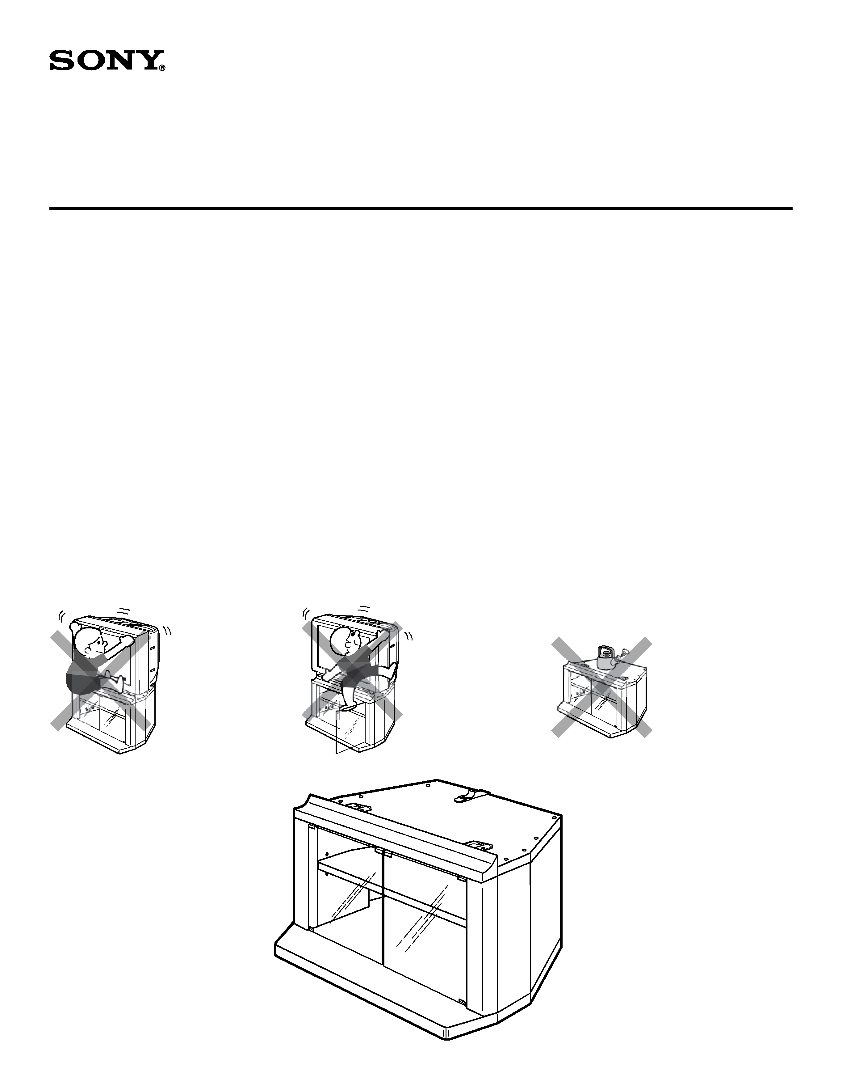
ASSEMBLED STAND /
SOPORTE ENSAMBLADO
To avoid serious
injury, do not allow
children to hang from
the television set.
Para evitar lesiones
severas, no permita
que los niños se
cuelguen del
conjunto del televisor.
To avoid injury to the
user and damage to
the stand, do not use
the shelf as a step.
Para evitar lesiones
al usuario y daño al
mueble, no use el
estante como
escalon.
Do not place hot objects
on top of the stand.
Doing so may result in
permanent damage to
the surfaces.
No coloque objetos
calientes arriba del
mueble. El hacerlo
puede resultar en daño
permanente a las
superficies.
WARNING / ADVERTENCIA
SU-32FD4:
KV-32FS12, KV-32FV16
KV-32FS16, KV-32FV26
KV-34FV16, KV-34FX260
KV-32FV27, KV-32FS13
KV-32FS17, KV-34FS13
KV-34FS17
SU-36FD4:
KV-36FS12, KV-36FV16
KV-36FS16, KV-36FV26
KV-36FS13, KV-38FS17
KV-36FS17, KV-36FV27
11
XW2814 1
XW2815
21
XW2615 1
XW2623
31
XW2663 1
XW2624
41
XW2617 1
XW2625
51
XW2618 1
XW2626
61
XW2619 1
XW2627
71
XW2620 1
XW2628
82
XW2621 2
XW2629
91
XW2376-1 1
XW2384-1
10
2
P0219
2
P0230
11
2
G0337
2
G0328
A1
M0018
1
M0018
B4
M0019
4
M0019
C2
P0236
2
P0236
D2
G0095
2
G0095
E2
M0056
2
M0056
F2
S0034
2
S0034
G8
S0035
8
S0035
H
1 S0122
1
S0122
I10 S0030
11
S0030
J8
B0077
8
B0077
K8
B0056
8
B0056
L4
P0010
4
P0010
M
1 P0159-1 1
P0159-1
N
2 M0026
2
M0197
SU-32FD4
SU-32FD4
SU-36FD4
SU-36FD4
MODEL:
MODELO:
O2
M0027
2
M0198
P1
P0178
1
P0178
Q4
P0203
4
P0203
R8
W0092
8
W0092
S1
P0225
1
P0231
T1
P0226
1
P0232
U1
P0227
1
P0233
V1
P0228
1
P0234
W1
P0229
1
P0235
SU-32FD4
SU-32FD4
SU-36FD4
SU-36FD4
MODEL:
MODELO:
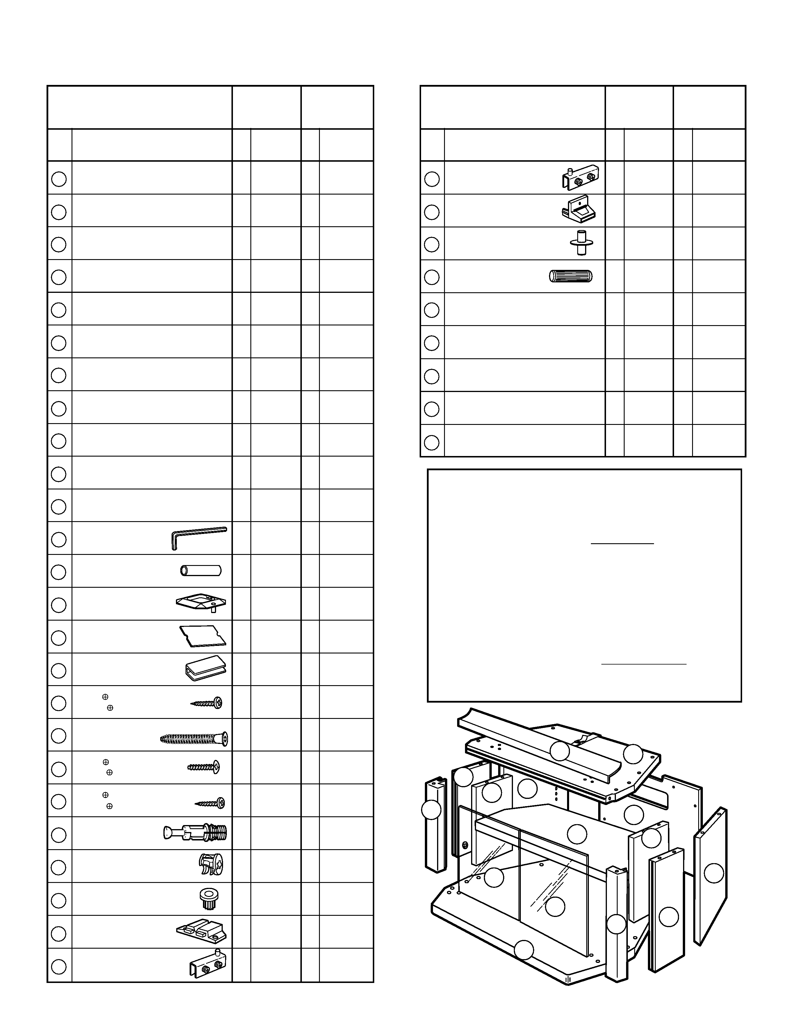
PARTS LIST
LISTA DE PARTES
REPLACEMENT PARTS INFORMATION
(TV stand parts only)
Review parts list before assembly.
Please examine all packing material before discarding.
If any parts are missing or damaged, identify and refer to
the instructions on the enclosed warranty card.
To purchase replacement parts only, call the telephone
number listed below.
1-619-661-6136 for residents of the United States.
INFORMACION PARA PARTES DE REEMPLAZO
(Solo para soporte de TV)
Revise la lista de partes antes de ensamblar.
Por favor examine el contenido del empaque antes de tirarlo.
Si alguna parte falta o esta dañada, identifiquela y siga las
i
instrucciones para reportarla en la tarjeta de garantía.
Para ordenar partes de reemplazo, llame al tel.
1-619-661-6136 para residentes de los Estados Unidos.
1
2
3
4
5
6
7
8
S
9
11
11
10
10
8
Item
Description
Qty
Part No.
Qty
Part No.
Artículo Descripción
Cant
No.parte
Cant
No.parte
Top board
Repisa superior
Adjustable shelf
Repisa ajustable
Base board
Repisa inferior
Right front
Frontal derecho
Left front
Frontal izquierdo
Right back
Posterior derecho
Left back
Posterior izquierdo
Inner board
Soporte interior
Back panel
Panel trasero
Front panel
Panel frontal
Glass door
Puerta de vidrio
Allen wrench
Llave Allen
Metal tube
Tubo metalico
Stop guide
Topes guía
Cushion
Almohadilla
Strike plate
Placa receptora
Screw
M3x16
Tornillo
M3x16
Screw (Hex. Socket head)
Tornillo Confirmat
Screw
M4x16
Tornillo
M4x16
Screw
#6x5/8"
Tornillo
#6x5/8"
Spreading bolt
Esprea moldeada
Cam casting (pre-installed)
Leva moldeada (pre-instalada)
Bushing
Buje
Magnet
Receptor magnético
Hinge
Bisagra
Item
Description
Qty
Part No.
Qty
Part No.
Artículo Descripción
Cant
No.parte
Cant
No.parte
Hinge
Bisagra
TV clip holder
Hevilla de plastico
Plastic pin
Alfiler plastico
Dowel Ø8x30
Espiga Ø8x30
Ornamental cover
Cubierta ornamental
Side cap FS (Right)
Tapa de lado FS (Derecha)
Side cap FS (Left)
Tapa de lado FS (Izquierda)
Side cap FV (Right)
Tapa de lado FV (Derecha)
Side cap FV (Left)
Tapa de lado FV (Izquierda)
Arrow direction shows front.
La dirección de la flecha indica el frente.
1
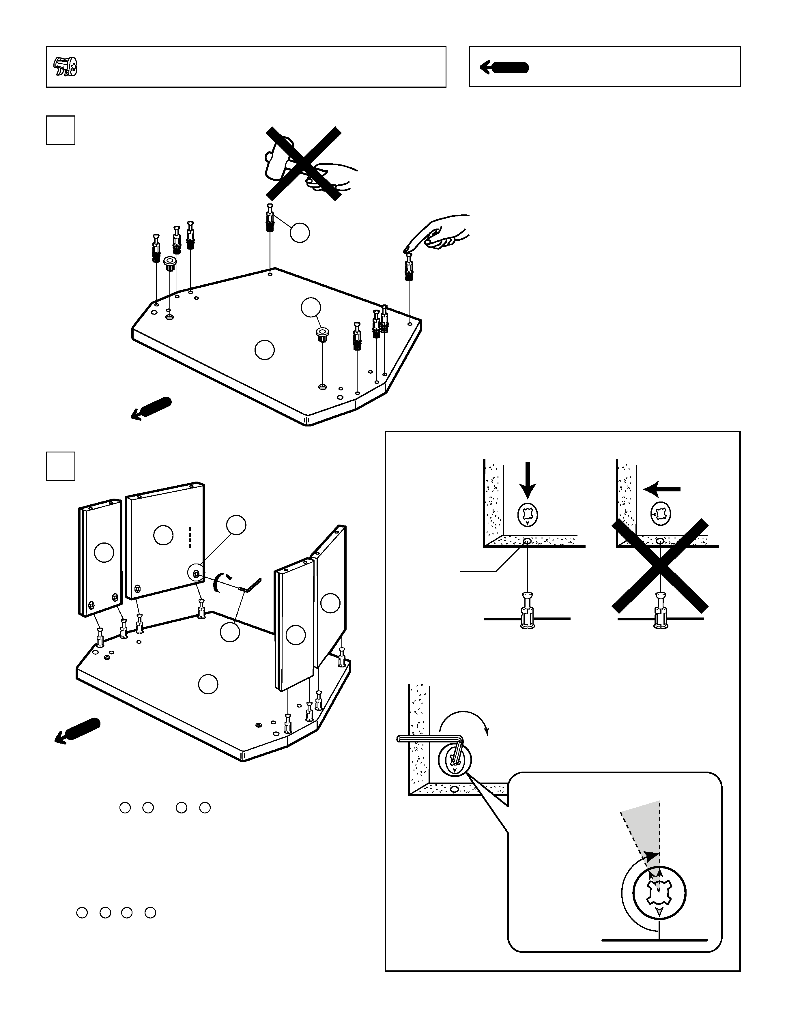
NOTE: Cam casts are pre-installed into wood pieces.
NOTA: Las "levas moldeadas" estan pre-instaladas en las piezas de madera.
2
CORRECT
CORRECTO
INCORRECT
INCORRECTO
NOTE: The arrow mark on the cam casts must
point towards the edge of board.
NOTA: La flecha señalada en la "leva moldeada"
debe apuntar hacia la orilla de la tabla.
1
2
TO AVOID A GAP BETWEEN FRONT AND BACK
PANELS ( 4 & 6 and 5 & 7 ):
When attaching side fronts and side backs to the base
board do not tighten the cam. For proper alignment,
hold the panels in place, and then finish tightening the
cam.
PARA EVITAR UNA ABERTURA ENTRE LOS
LATERALES FRONTALES Y POSTERIORES
( 4 & 6 y 5 & 7 ):
Al ensamblar los laterales frontales y posteriores a la
repisa inferior no apriete las levas moldeadas. Para una
alineación apropiada, sujete los laterales en posición, y
entonces termine de apretar las levas moldeadas.
Spreading
bolt hole
Agujero para
la esprea moldeada
OK
Turn clockwise.
Dele vueltas en el
sentido de las
manecillas del reloj.
3
J x 8
L x 2
4
5
3
6
7
A
K x 8
6
3
5
4
10
8
3
Q x 4
7
4
6
10
1
4
6
3
10
G x 8
A
8
10
7
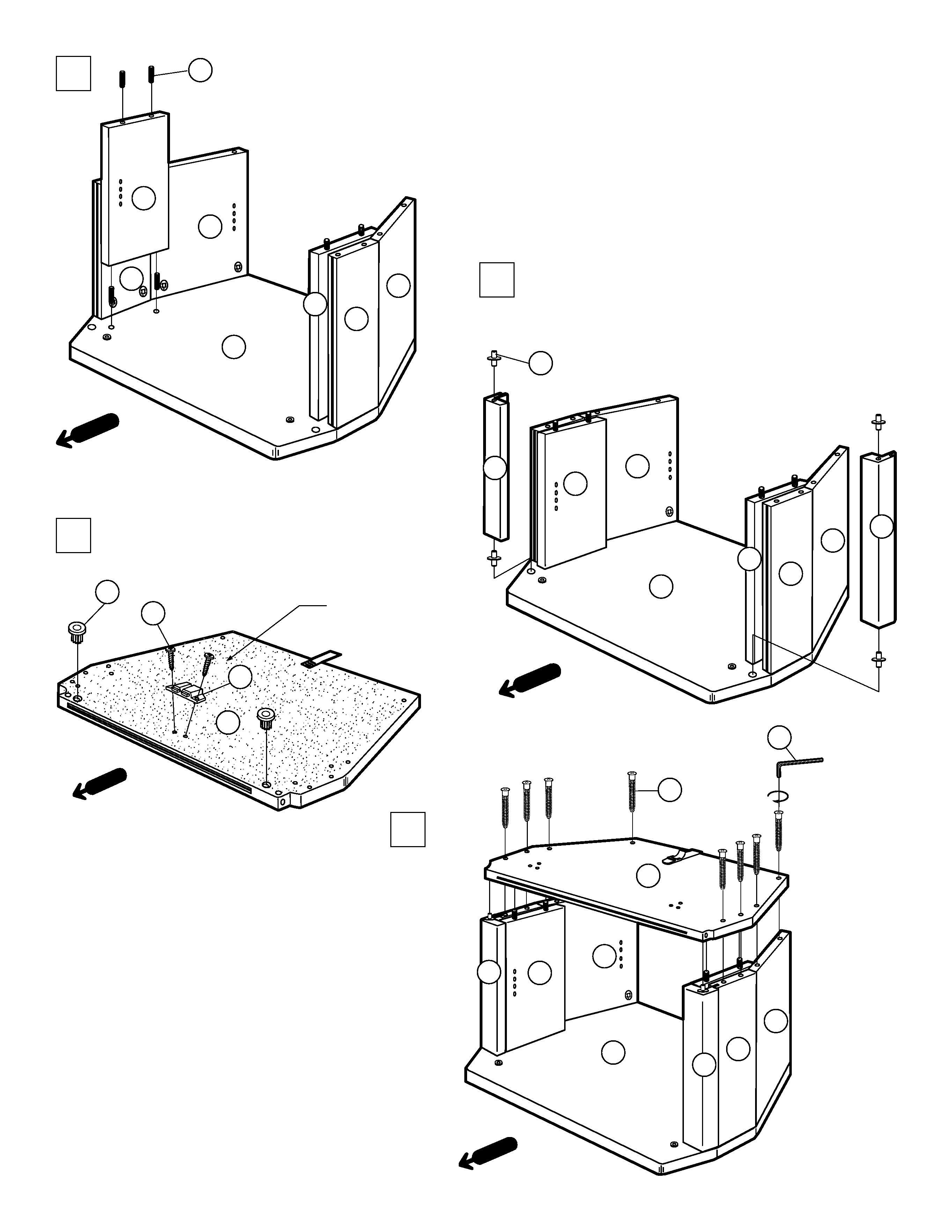
When attaching the top board to the front and back panels do
not tighten the screws. For proper alignment, hold the panels in
place, and then finish tightening the screws.
(Also see step 2 "To avoid a gap between panels")
Al instalar la repisa superior a los laterales frontales y
posteriores no apriete los tornillos. Para una alineación
apropiada, sujete los laterales en posición, y entonces termine
de apretar los tornillos.
(También ver paso 2 "Para evitar una abertura entre laterales")
8
R x 8
8
3
7
5
4
6
8
L x 2
UNFINISHED SIDE
Lado sin acabado
M
F x 2
1
Tighten these 2 screws first.
Apriete estos 2 tornillos
primero.
8
7
Tighten these 2 screws first.
Apriete estos 2 tornillos
primero.
Choose the appropriate holes for shelf
adjustment depending on the components to
be installed.
Escoja los agujeros adecuados para ajustar la
repisa dependiente a los componentes que se
instalaron.
SU-36FD4
SU-32FD4
DIMENSIONS OF GLASS DOOR
DIMENSIONES DE LA PUERTA DE VIDRIO
LEFT DOOR
LA PUERTA IZQUIERDA
DE VIDRIO
RIGHT DOOR
LA PUERTA DERECHA
DE VIDRIO
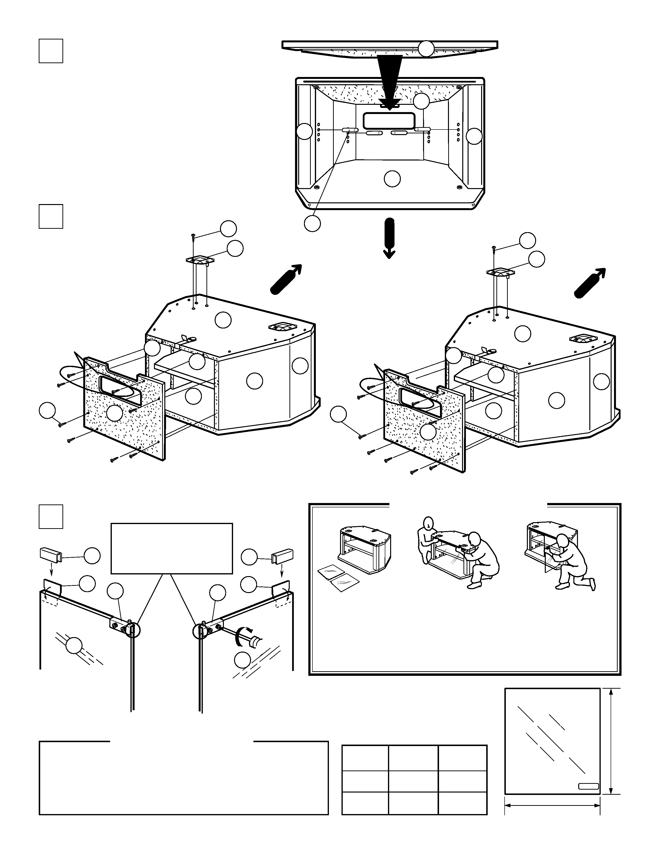
9
DISTANCE
DISTANCIA
A
B
SU-32FD4
mm
(inch)
326.1
(12 27/32)
434.3
(17 3/32)
SU-36FD4
mm
(inch)
375.0
(14 3/4)
384.0
(15 1/8)
TEMPERED GLASS
A
B
6
7
2
5
3
1
I x 8
C x 2
6
7
2
5
3
1
I x 9
C x 2
B x 4
10
3
1
2
10
9
9
Glass door must not extend
past the hinges.
La puerta de vidrio no debe
de sobrepasar las bisagras.
N
O
D
E
D
E
11
11
PLEASE INSTALL GLASS DOORS AFTER THE STAND IS SET AT THE
FINAL LOCATION.
REMOVE GLASS DOORS PRIOR TO MOVING THE STAND.
FAVOR DE INSTALAR LAS PUERTAS DE VIDRIO DESPUES DE
COLOCAR EL MUEBLE EN SU POSICION FINAL.
QUITE LAS PUERTAS DE VIDRIO ANTES DE MOVER EL MUEBLE.
Tempered Glass / Vidrio Templado
The glass panels in this stand are made of tempered glass. Although it is more
shock-resistant than ordinary glass, tempered glass may shatter if it receives a
sudden shock. Be careful not to drop or scratch the glass.
La puerta de vidrio de este soporte de televisor esta hecha de vidrio templado.
Aunque es mas resistente a impactos que el vidrio ordinario, puede fracturarse
si recibe un golpe repentino. Tenga cuidado en no dejar caer o en rayar el vidrio.
CAUTION / PRECAUCION
I x 2
I x 2