ST-SB920
AEP Model
UK Model
SERVICE MANUAL
FM STEREO FM-AM TUNER
MICROFILM
SPECIFICATIONS
FM tuner section
Frequency range
87.5 108.0 MHz
Aerial terminals
75
, unbalanced
Intermediate frequency
10.7 MHz
Sensitivity
at 26 dB quieting
(mono) 10.3 dBf, 0.9
µV/75
at 46 dB quieting
(stereo) 38.5 dBf, 23
µV/75
Usable sensitivity (IHF)
10.3 dBf, 0.9
µV/75
S/N
at 40 kHz deviation
80 dB (mono), 76 dB (stereo)
Harmonic distortion
WIDE
0.035 % (mono), 0.045 (stereo)
NARROW
0.055 % (mono), 0.075 (stereo)
Frequency response
30 Hz 15 kHz
(+0.3/0.7 dB)
Separation
50 dB at 1 kHz
Selectivity
at 400 kHz
WIDE 85 dB
NARROW 90 dB
at 300 kHz
WIDE 45 dB
NARROW 70 dB
Output
at 40 kHz deviation 600 mV
AM tuner section
Frequency range
MW: 522 1,611 kHz (9 kHz step)
LW: 144 288 kHz (1 kHz step)
Intermediate frequency
450 kHz
Usable Sensitivity
(with AM loop aerial)
MW: 200
µV/m
LW: 700
µV/m
Signal-to-noise ratio
MW: 54 dB (50 mV/m, 999 kHz)
LW: 50 dB (50 mV/m, 216 kHz)
Harmonic distortion
0.3% (50 mV/m, 400 Hz)
Selectivity
50 dB
General
Power requirements
220 230 V, AC 50/60 Hz
Power consumption
12 W
Input impedance
75
Input connector
IEC-male
Dimensions
430
× 86 × 295 mm (w/h/d)
Weight
3.95
Supplied accessories
Audio cord (1)
AM loop aerial (1)
FM wire aerial (1)
EON connecting cord (1)
Design and specifications are subject to change without notice.
MC-Service
-- 2 --
1.
GENERAL ······································································ 2
2.
TEST MODE ·································································· 3
3.
ELECTRICAL ADJUSTMENT ································· 5
4.
DIAGRAMS
4-1.
Circuit Board Location ······················································· 8
4-2.
Schematic Diagram DISPLAY SECTION ·················· 9
4-3.
Printed Wiring Board DISPLAY SECTION ············· 11
4-4.
Printed Wirng Board TUNER SECTION ················· 13
4-5.
Schematic Diagram TUNER SECTION (1/2) ·········· 15
4-6.
Schematic Diagram TUNER SECTION (2/2) ·········· 17
4-7.
IC Pin Function ································································ 19
4-8.
IC Block Diagram ···························································· 20
6.
EXPLODED VIEWS
6-1.
Front Panel and Case Section ··········································· 21
6-2.
Panel and Display Section ················································ 22
7.
ELECTRICAL PARTS LIST ··································· 23
TABLE OF CONTENTS
SECTION 1
GENERAL
SAFETY-RELATED COMPONENT WARNING!!
COMPONENTS IDENTIFIED BY MARK ! OR DOTTED LINE WITH
MARK ! ON THE SCHEMATIC DIAGRAMS AND IN THE PARTS
LIST ARE CRITICAL TO SAFE OPERATION. REPLACE THESE
COMPONENTS WITH SONY PARTS WHOSE PART NUMBERS
APPEAR AS SHOWN IN THIS MANUAL OR IN SUPPLEMENTS
PUBLISHED BY SONY.
PARTS No.
MODEL
MODEL IDENTIFICATION
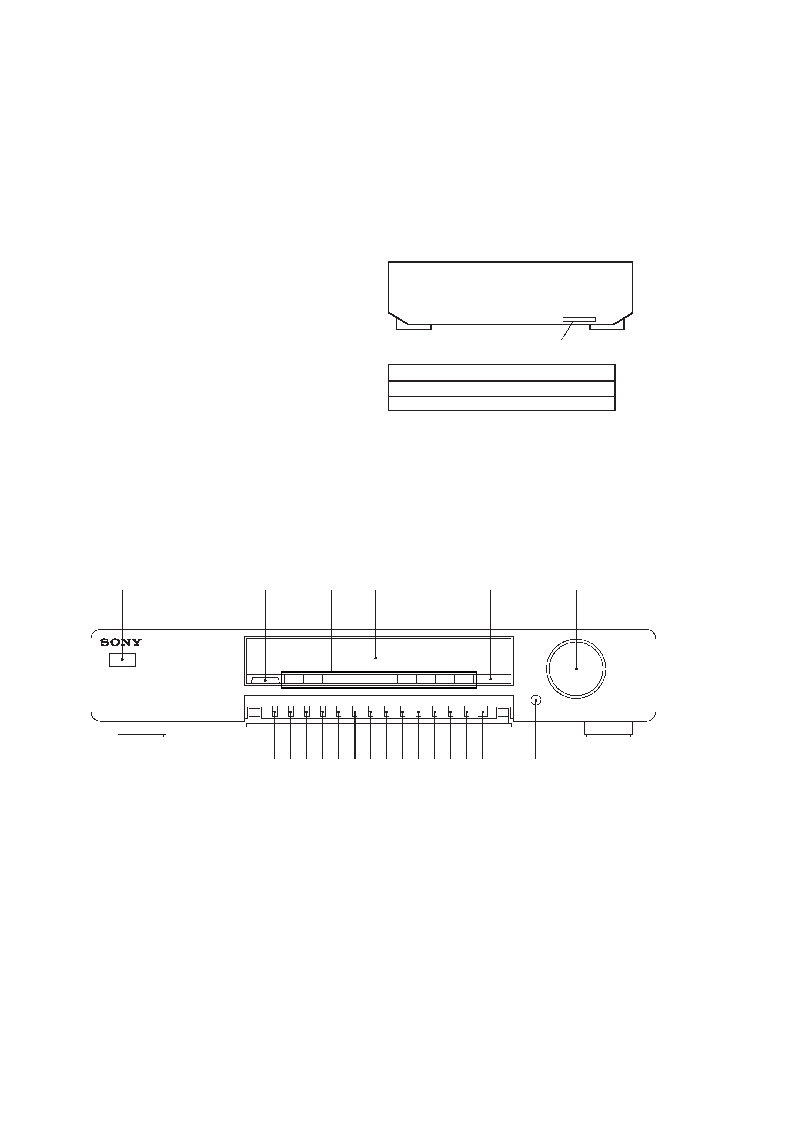
-- BACK PANEL --
4-998-494-0
4-998-494-1
AEP model
UK model
,,,,,,,,
yyyyyyyy
PART NO.
1 POWER swtich (U)
2 SHIFT button
3 Numeric button
4 Display window
5 DIRECT button
6 TUNING/SELECT knob
7 DISPLAY button
8 PTY button
9 TA button
0 NEWS/INFO button
!¡ AUTO-BETICAL SELECT button
1
2
3
5
4
6
7890!¡ !TM!£!¢!!§ !¶!· !ª@º
@¡
Location of Controls
!TM MEMORY button
!£ BAND button
!¢ ON/OFF button
! ANTENNA button
!§ FM MODE button
!¶ CHARACTER button
!· MENU button
!ª RETURN button
@º ENTER button
@¡ TUNING MODE button
-- 3 --
SECTION 2
TEST MODE
1. Circuit Check Mode
Set to the reception frequency that the curcuit can STEREO RDS stations. (Set the input level to above 70 dB.)
This enables circuit check to be performed in any of the reception modes-FM, AM (MW, LW). Set to a desired band before setting the test
mode.
1. Turn OFF the power.
2. While pressing 4 and AUTO-BETICAL SELECT together, turn ON
U .
· The items in the following table will be checked automatically in order every 2 seconds.
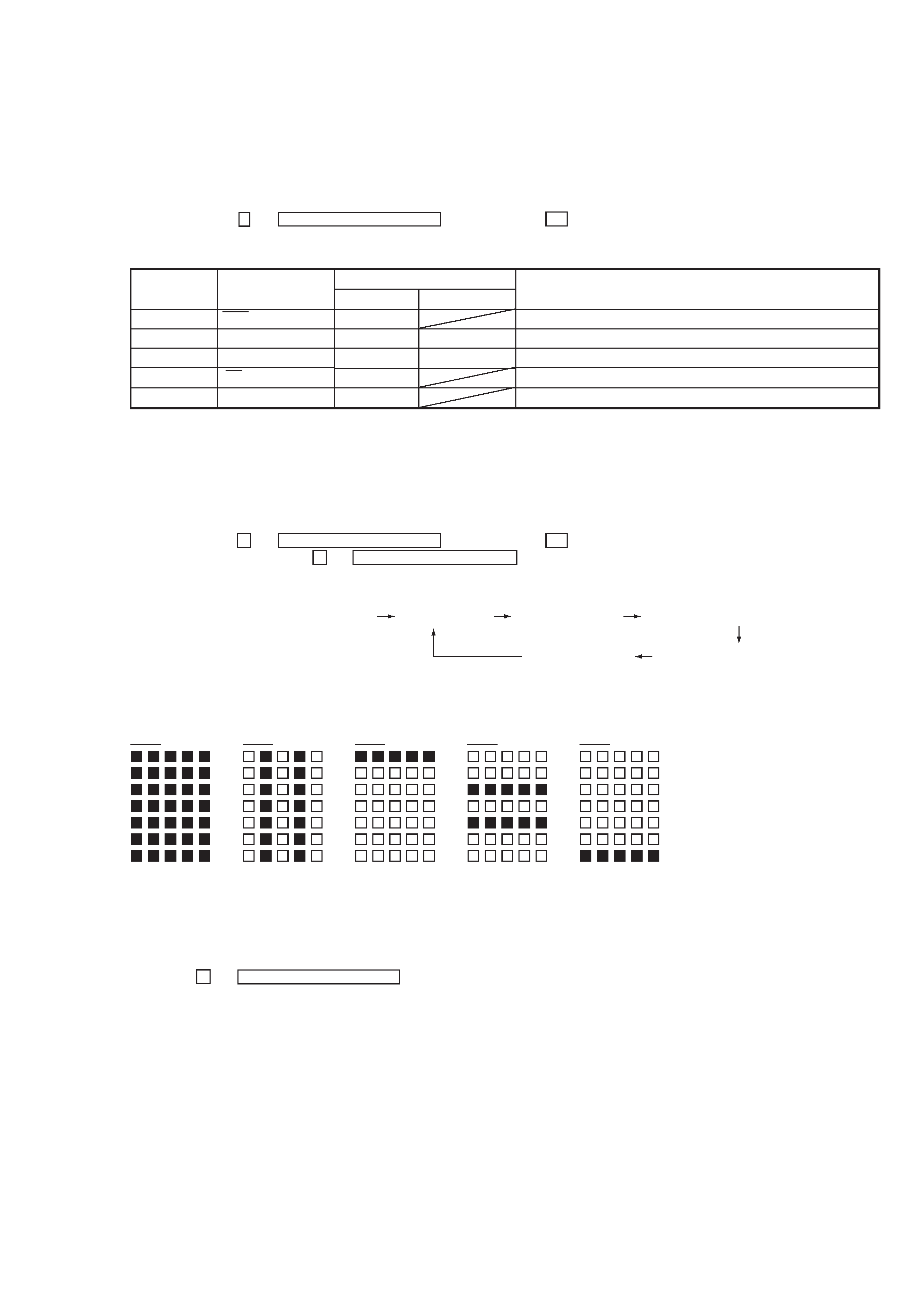
Display
Tuned
IF Frq
Sig Level
Stereo
RDS Signal
Items
AST signal = LOW
IF COUNT OK
SI LEVELh 70dB
ST signal = LOW
RDS DATA OK
FM RDS
OK or NG
OK or NG
OK or NG
OK or NG
OK or NG
AM (MW, LW)
OK or NG
OK or NG
NG
IC251 NG, RV251 adjustments
FE101, IC251 NG, or IF count buffer amp (Q251, Q401) NG
IC221 NG, RV221 adjustments
IC301 NG, RV301 adjustments
IC801 NG
DISPLAY
NOTE : The preset data will be erased when this test mode is used. Therefore, take down the data before setting this mode and preset the
data again after completing operations in this mode.
2. Display Tube Check and KEY Check mode
1. Turn OFF the power.
2. While pressing 1 and AUTO-BETICAL SELECT together, turn ON
U .
3. While continuously pressing 1 and AUTO-BETICAL SELECT together, check the following.
Indication test pattern
* The indication test pattern from
2 to 5 are indicated on only even grids.
The display changes every 1 sec.
4. Release 1 and AUTO-BETICAL SELECT . The KEY CHECK mode will be set.
5. All key numbers will be displayed.
Key Number : 27
6. Each time the key is pressed, the key number will be counted down.
Each key will be counted only once, at the first time.
7. When all keys have been pressed, the process will end.
Microcomputer version indication (1 sec)
All light up "7F"
Dot area only "60"
Dot area only "7E"
Dot area only "3D"
Dot area only "5F"
1 7F
2 60
3 7E
4 3D
5 5F
MC-Service

-- 4 --
3. Entering the Factory Preset (In case perform just to write memory of the Factory Preset.)
NOTE : As contents of the Factory Preset will be written into memory after completing this check mode, delete contents of memory
according to 4. Forced RESET.
1. Turn OFF the power.
2. While pressing 3 and AUTO-BETICAL SELECT together, turn ON
U .
4. Forced RESET (Used to delete the contents of Factory Preset when it is written into the preset memory.)
Clears all the RAMs and sets the initial state
1. Turn OFF the power.
2. While pressing 5 and AUTO-BETICAL SELECT together, turn ON
U .
3. When "All clear" is indicated on the display tube, it means that "Forced Reset" has been completed.
-- 5 --
SECTION 3
ELECTRICAL ADJUSTMENTS
Precautions in Repairing
If the front end unit fails, it is difficult to repair the inner circuits, so
replace the entire front end unit.
Set "IF : WIDE" after the all adjustments.
· Standard Setting of FM Stereo RF Signal Generator.
How to switch IF BAND : WIDE/NARROW and ANT
ATT : ON/OFF
Method 1:
1. Set the reception mode to FM.
2. Push the MENU button and turn the TUNING/SELECT to
indicate "Reception" on the fluorecent display tube, then press
the ENTER button.
3. Rotate the TUNING/SELECT knob in the clokwise direction.
(Proceeds onto the step 5 when rotated in the counterclokwise
direction.)
4. Turn the TUNING/SELECT knob to indicate "ANT ATT :
OFF" on the fluorescent display tube, then press the ENTERl
button.
5. Turn the TUNING/SELECT knob to indicate "IF : NARROW"
or "IF : WIDE" on the fluorescent display tube, then press the
lENTER button.
When the IF BAND : NARROW is set, "NARROW" is
indicated on the fluorescent display tube.
6. Set WIDE after the operation.
* When set to standby for inputs using the TUNING/SELECTl
knob, "SELECT" is indicated on the fluorecent display tube.
Method 2:
After the test modes "2. Display Tube Check and KEY Check mode"
or "3. Entering the Factory Preset", "IF : NARROW" and "IF :
WIDE" are switched every time pressing RETURN button the IF
BAND : NARROW is set "NARROW" is indicated on the
fluorescent display tube.
Likewise, the mode can be switched between "ANT ATT : ON"
and "ANT ATT : OFF". When set to ANT ATT : ON, the fluorescent
display tube indicates ANT ATT.
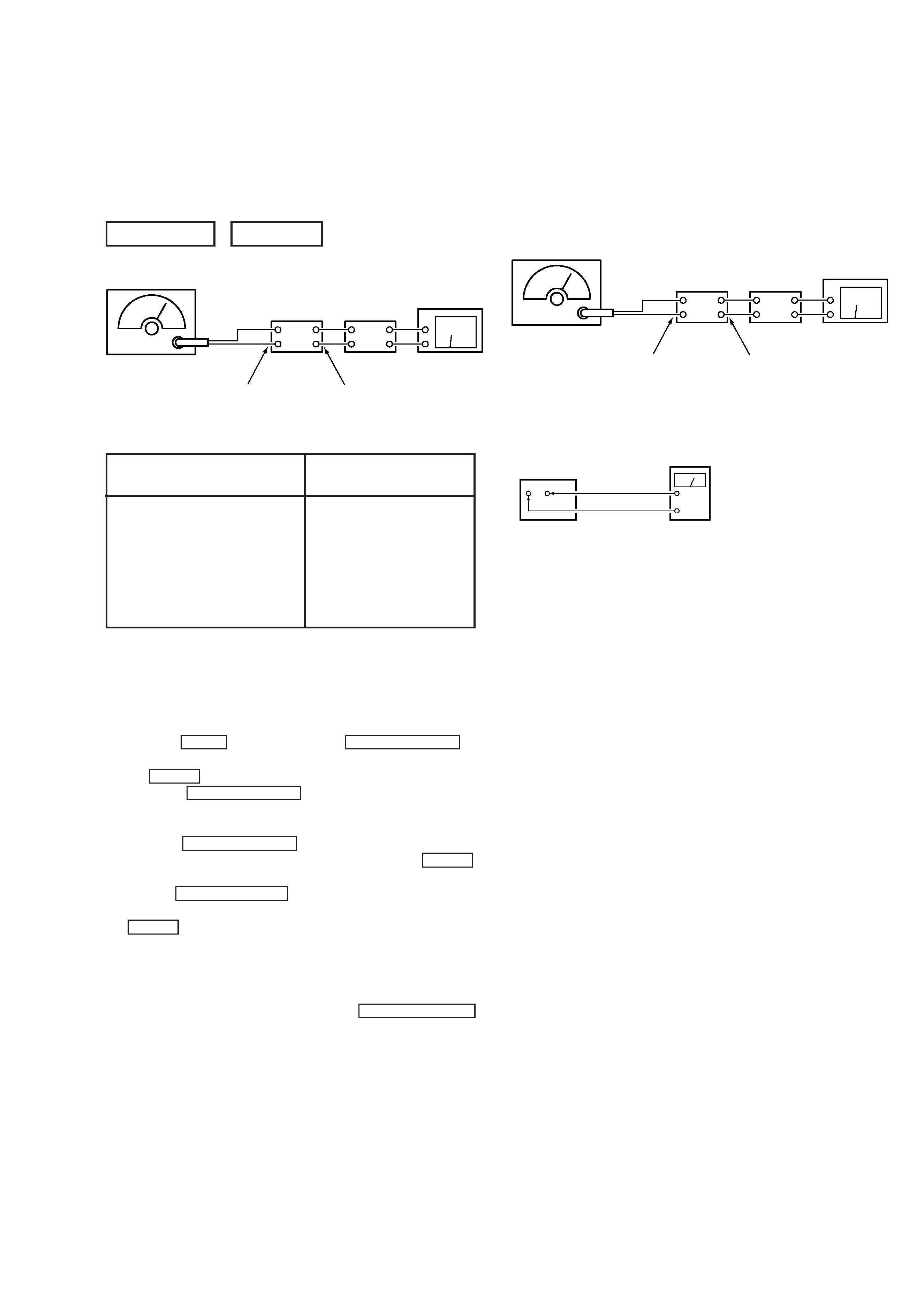
FM SECTION
0dB = 1µV
set
FM RF SSG
1kHz
highpass
filter
distortion meter
FM ANTENNA (75
)
LINE OUT
STEREO STANDARD SIGNAL
MONAURAL
STANDARD SIGNAL
Carrier frequency : 98MHz
Modulation : Audio 1kHz
Main channel (L+R) : 33.75kHz
deviation
Sub channel (LR)
: 33.75kHz
deviation
Pilot
: 7.5kHz
Deviation
Carrier frequency : 98MHz
Modulation : Audio 1kHz
75kHz deviation
FM Discriminator ADJUSTMENT
(NULL and MONO Distortion Adjustment)
Setting:
IF BAND : WIDE
ANT ATT : OFF
Procedure:
1. Tune the set to 98 MHz.
2. Adjust IFT252 for 0V reading on the digital voltmeter.
................... NULL
3. Adjust IFT253 for a minimum reading on the distortion meter.
................... MONO Distortion (THD)
4. Repeat the adjustments of 2 and 3 several times.
Note : When replacing the ceramic filter, perform this alignment.
set
FM RF SSG
1kHz
highpass
filter
distortion meter
FM ANTENNA (75
)
Modulation : Monaural Standard signal
Output level : 6mV (76dB) (at 75
open)
LINE OUT
Digital Voltmeter
(DC range)
TP251
NULL terminal
MC-Service