ST-SA50ES
US Model
SERVICE MANUAL
FM STEREO FM-AM TUNER
MICROFILM
SPECIFICATIONS
FM tuner section
Frequency range
87.5 108.0 MHz
Antenna terminals
75
, unbalanced
Intermediate frequency
10.7 MHz
Sensitivity
at 26 dB quieting
(mono) 10.3 dBf, 0.9
µV/75
at 46 dB quieting
(stereo) 38.5 dBf, 23
µV/75
Usable sensitivity (IHF)
10.3 dBf, 0.9
µV/75
S/N
at 40 kHz deviation
95 dB (mono), 86 dB (stereo)
Harmonic distortion
WIDE
0.008 % (mono), 0.02 % (stereo)
NARROW
0.04 % (mono), 0.07 % (stereo)
Frequency response
15 Hz 15 kHz
(±0.2 dB)
Separation
65 dB at 1 kHz
Selectivity
at 400 kHz
WIDE 80 dB
NARROW 90 dB
at 300 kHz
WIDE 45 dB
NARROW 70 dB
Output
at 40 kHz deviation 600 mV
AM tuner section
Frequency range
AM : 530 1,710 kHz (10 kHz step)
Intermediate frequency
450 kHz
Usable sensitivity
(with AM loop antenna)
200
µV/m
Signal-to-noise ratio
AM : 54 dB (50 mV/m, 1,050 kHz)
Harmonic distortion
0.3% (50 mV/m, 400 Hz)
Selectivity
50 dB
General
Power requirements
120 V, AC 60 Hz
Power consumption
13 W
Dimensions
16 15/16
× 3 7/
8
× 13 3/
8
in.
(430
× 98 × 340 mm)
Weight
9 lbs. 1 oz.(4.1 kg)
Supplied accessories
Audio cord (1)
AM loop antenna (1)
FM wire antenna (1)
Antenna adapter (1)
Design and specifications are subject to change without notice.
-- 2 --
1. GENERAL ............................................................................ 3
2. DISASSEMBLY
2-1.
Panel, Front Assembly ........................................................ 4
2-2.
Display Board, Encoder Board, AC SW Board .................. 4
2-3.
Panel Front ......................................................................... 4
3. TEST MODE ........................................................................ 5
4. ELECTRICAL ADJUSTMENTS ................................... 7
5. DIAGRAMS
5-1.
Circuit Boards Location ................................................... 11
5-2.
Printed Wiring Board Display Section ....................... 13
5-3.
Schematic Diagram Display Section .......................... 15
5-4.
Printed Wiring Board Tuner Section .......................... 17
5-5.
Schematic Diagram Tuner Section (1/2) ..................... 19
5-6.
Schematic Diagram Tuner Section (2/2) ..................... 21
5-7.
IC Pin Function ................................................................ 23
5-8.
IC Block Diagrams ........................................................... 24
6. EXPLODED VIEW
6-1.
Front Panel and Case Section ........................................... 25
7. ELECTRICAL PARTS LIST ......................................... 26
TABLE OF CONTENTS
SAFETY-RELATED COMPONENT WARNING!!
COMPONENTS IDENTIFIED BY MARK
! OR DOTTED LINE WITH
MARK
! ON THE SCHEMATIC DIAGRAMS AND IN THE PARTS
LIST ARE CRITICAL TO SAFE OPERATION. REPLACE THESE
COMPONENTS WITH SONY PARTS WHOSE PART NUMBERS
APPEAR AS SHOWN IN THIS MANUAL OR IN SUPPLEMENTS
PUBLISHED BY SONY.
SAFETY CHECK-OUT
After correcting the original service problem, perform the
following safety checks before releasing the set to the customer:
Check the antenna terminals, metal trim, "metallized" knobs, screws,
and all other exposed metal parts for AC leakage. Check leakage as
described below.
LEAKAGE
The AC leakage from any exposed metal part to earth ground and
from all exposed metal parts to any exposed metal part having a
return to chassis, must not exceed 0.5 mA (500 microampers).
Leakage current can be measured by any one of three methods.
1.
A commercial leakage tester, such as the Simpson 229 or RCA
WT-540A. Follow the manufacturers' instructions to use these
instruments.
2.
A battery-operated AC milliammeter. The Data Precision 245
digital multimeter is suitable for this job.
3.
Measuring the voltage drop across a resistor by means of a
VOM or battery-operated AC voltmeter. The "limit" indication
is 0.75 V, so analog meters must have an accurate low-voltage
scale. The Simpson 250 and Sanwa SH-63Trd are examples of
a passive VOM that is suitable. Nearly all battery operated
digital multimeters that have a 2V AC range are suitable. (See
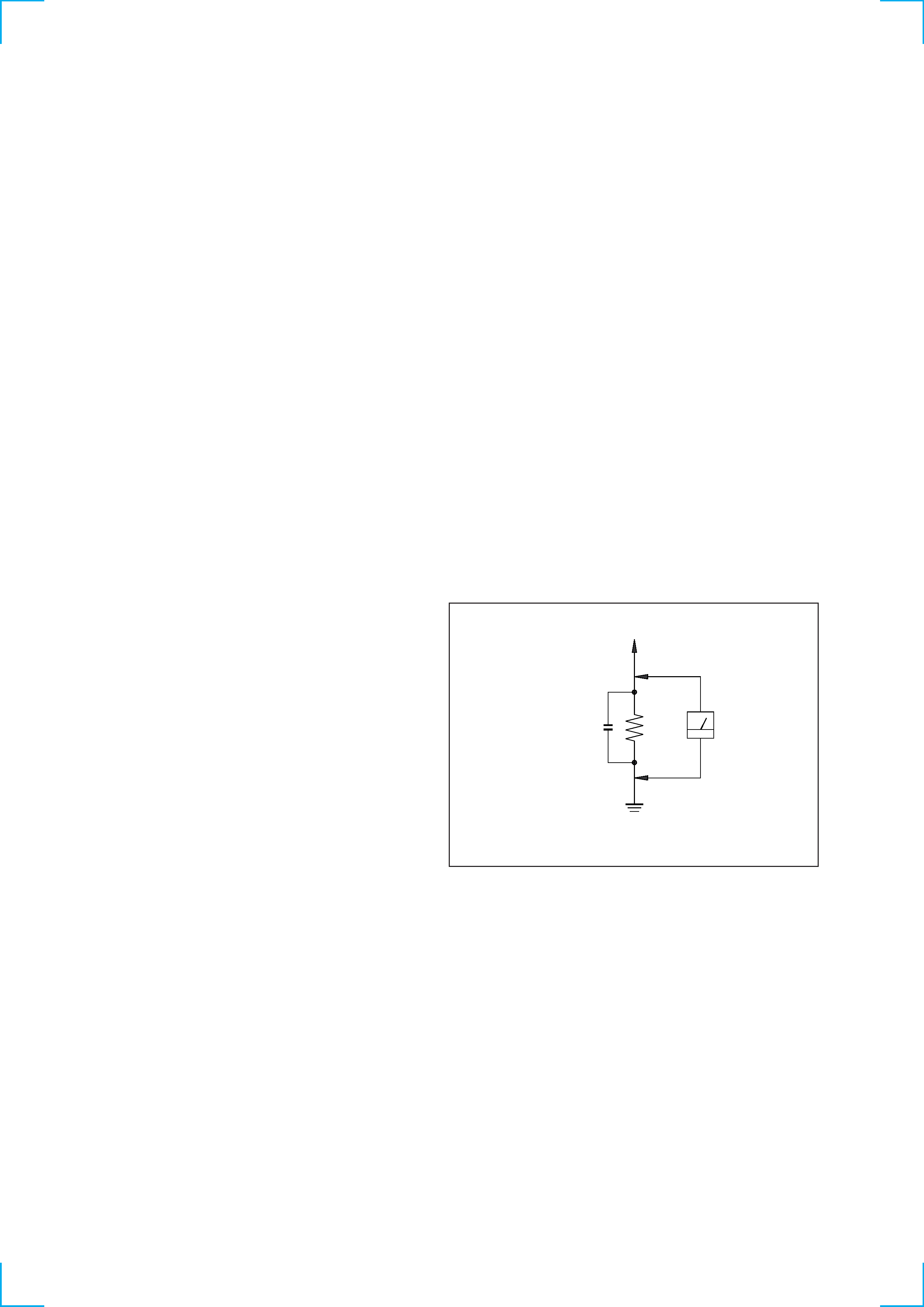
Fig. A)
Earth Ground
AC
voltmeter
(0.75V)
1.5k
0.15
µF
Fig. A. Using an AC voltmeter to check AC leakage.
To Exposed Metal
Parts on Set
-- 3 --
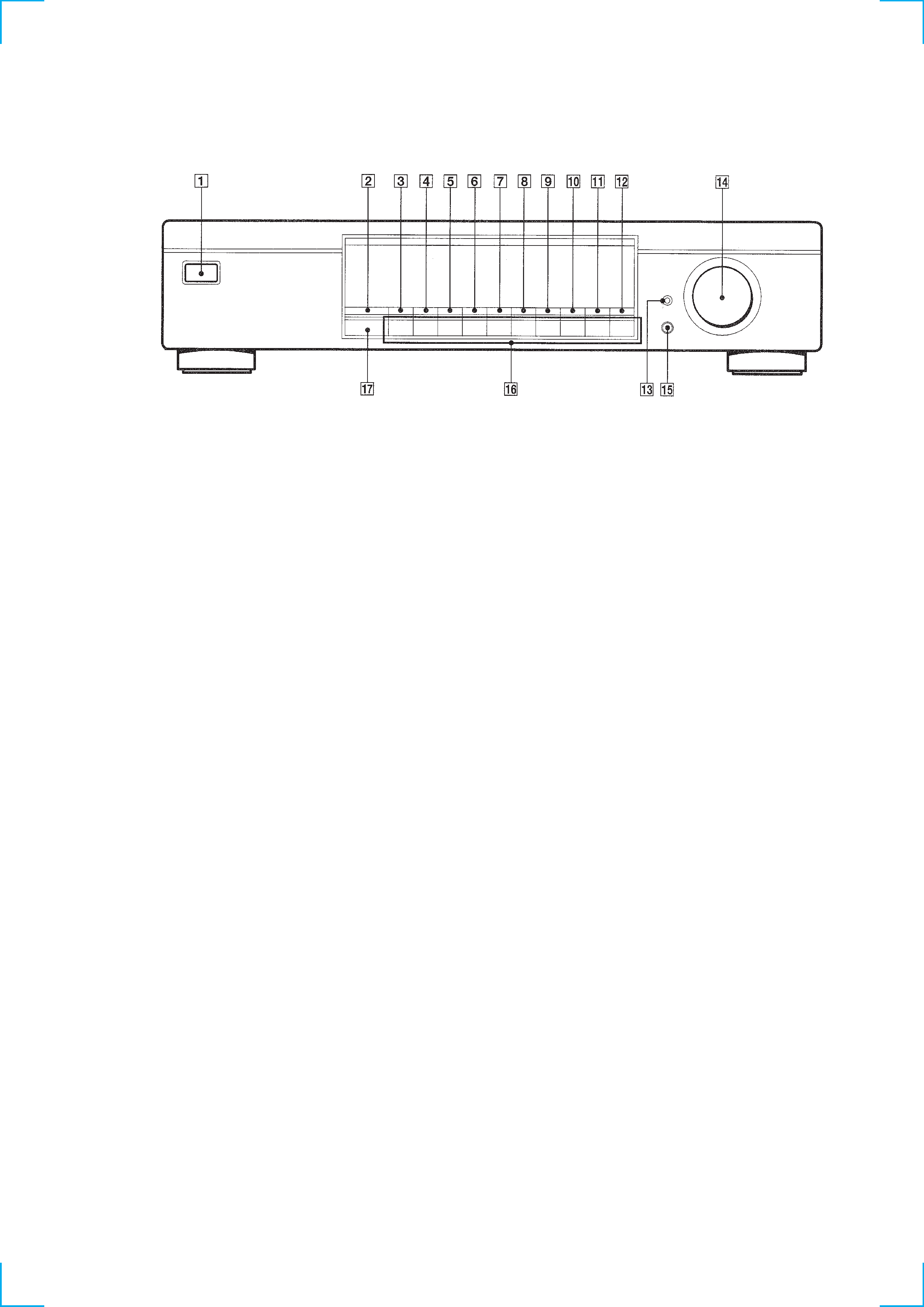
SECTION 1
GENERAL
1 POWER swtich (U)
2 DISPLAY button
3 ANTENNA button
4 ASM button
5 ANT ATT button
6 IF BAND button
7 FM MODE button
8 BAND button
9 MEMORY button
Location of Controls
0 CHARACTER button
!¡ MENU button
!TM RETURN button
!£ TUNE MODE button
!¢ TUNING/SELECT knob
! ENTER button
!§ NUMBER buttons
!¶ SHIFT button
-- 4 --
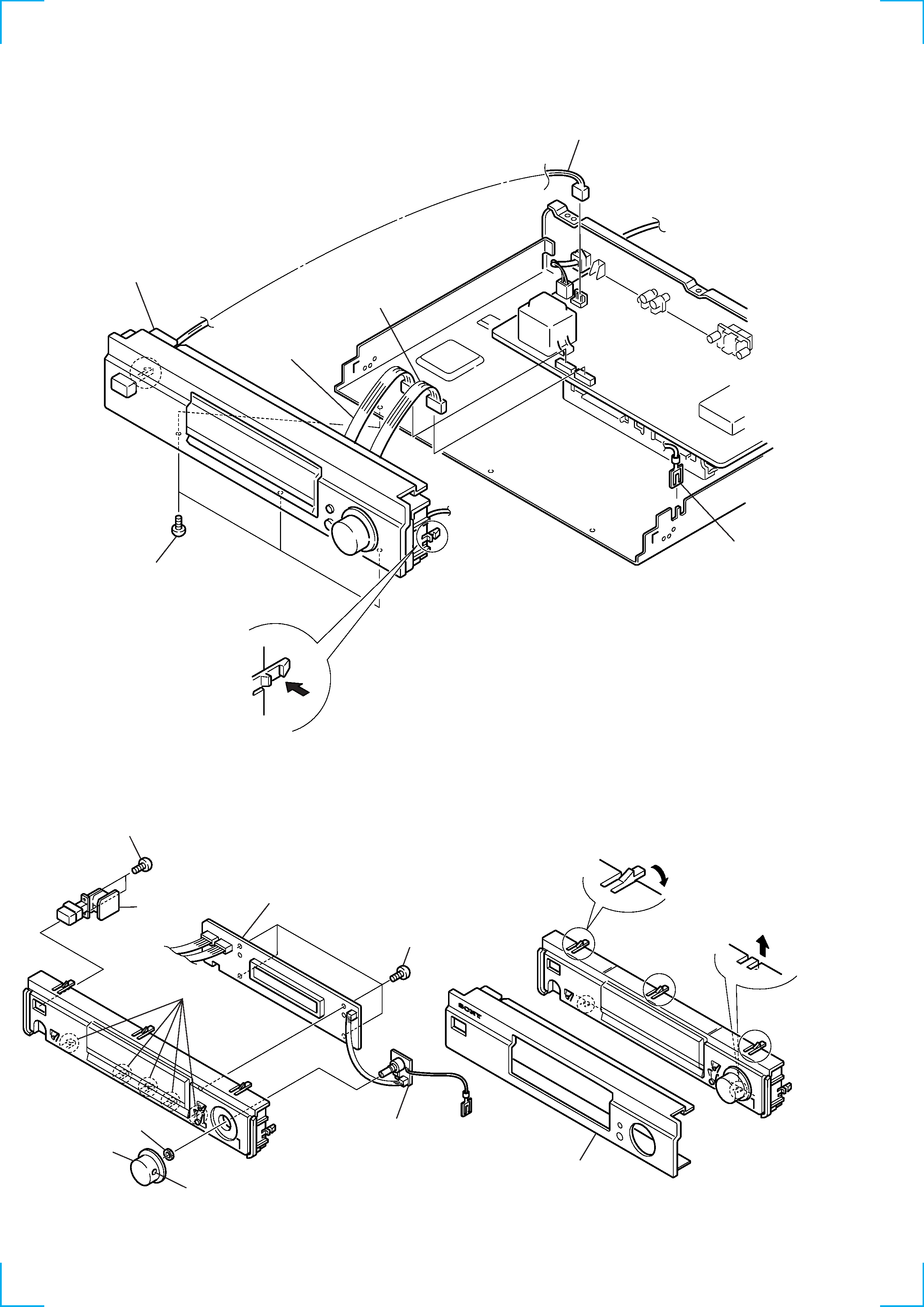
SECTION 2
DISASSEMBLY
Note : Follow the disassembly procedure in the numerical order given.
2-1. PANEL, FRONT ASSEMBLY
2-2. DISPLAY BOARD, ENCODER BOARD,
AC SW BOARD
2-3. PANEL, FRONT
3 Panel, front
2 Remove the two
lower claws in the
direction of the arrow.
1 While pressing the three claws
in the direction of the arrow,
pull the top of the panel slightly.
5 Three screws
(BV3
× 8)
7 Panel, front assembly
2 Connector
(CNP701:TUNER board)
3 Connector
(CNP702:TUNER board)
1 Connector
(CNP951:TUNER board)
4 Lead with connector
6 Remove the two claws
by pressing them in the
direction of the arrow.
2 Knob (T)
4 Four screws
(BV3
× 8)
8 Two screws
(BV3
× 8)
6 DISPLAY board
9 AC SW board
1 Loosen the screw.
7 ENCODER board
3 Nut supplied
with RV701
5 Remove the
five claws.
-- 5 --
SECTION 3
TEST MODE
1. Circuit Check Mode
1. Turn OFF the power.
2. While pressing 4 and MENU together, turn ON POWER .
· The items in the following table will be checked automatically in order every 2 seconds.
Display
Tuned
IF Frq
Sig Level
Stereo
Items
AST signal = LOW
IF COUNT OK
SI LEVEL > 70dB
ST signal = LOW
FM RDS
OK or NG
OK or NG
OK or NG
AM
OK or NG
OK or NG
NG
IC251 NG, RV251 adjustments
FE101, IC251 NG, or IF count buffer amp (Q251, Q401) NG
IC221 NG, RV221 adjustments
IC301 NG, RV301 adjustments
DISPLAY