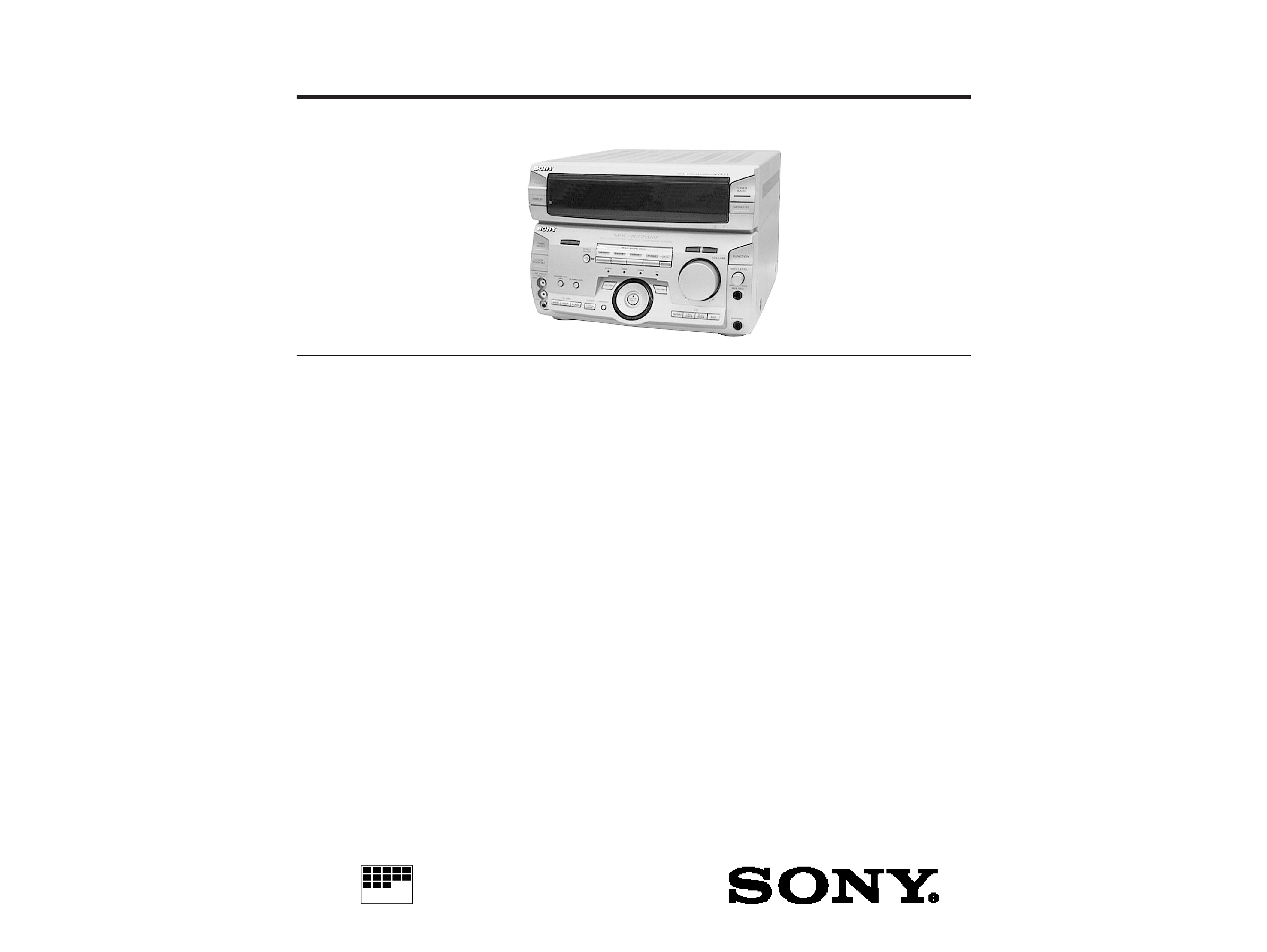
STR-W770
E Model
Australian Model
SERVICE MANUAL
FM STEREO/FM-AM RECEIVER
MICROFILM
STR-W770 is RECEIVER section in
MHC-W770AV.
SPECIFICATIONS
Tuner section
FM stereo, FM/AM superheterodyne tuner
FM tuner section
Tuning range
87.5-108.0MHz
Aerial
FM lead aerial
Aerial terminals
75 ohm unbalanced
Intermediate frequency 10.7MHz
AM tuner section
Tuning range
(Thai,Australian,E)
AM: 530-1,710kHz
(with interval set at 10kHz)
531-1,710kHz
(with interval set at 9kHz)
(EXCEPT Thai,Australian,E)
MW: 531-1,602kHz
(with interval set at 9kHz)
(EXCEPT Thai,Australian,E)
SW: 5.95-17.90MHz
(with interval set at 9kHz)
Intermediate frequency 450kHz
Aerial
AM loop aerial,
External aerial terminal
Video section
Inputs
AV INPUT VIDEO
(phone jack) :
1 Vp-p, 75 ohms
MONITOR OUT
(phone jack) :
1 Vp-p, 75 ohms
Amplifier section
DIN power output
80W +80W
(6 ohms at 1kHz, DIN)
Music power output
190W + 190W
(6 ohms at 1kHz, 10%, THD)
Inputs
MD/VIDEO 1 IN (phono jacks) : voltage 250 mV,
impedance 47 kilo ohms AV INPUT AUDIO
(phone jacks) : voltage 250 mV, impedance 47
kilo ohms
MIX/MIC (phone jack) :sensitivity 1mV,
impedance 10 kilo ohms
Outputs
MD/VIDEO 1 OUT
(phone jacks) : voltage 250
mV, impedance 1 kilo ohm
PHONES (stereo phone
jack) : accepts headphone
of 8 ohms or more.
SPEAKER : accepts
impedance of 6 to 16
ohms
SUPER WOOFER :
Voltage 1 V, impedance 1
kilo ohms
-- Continued on next page --
Manufactured under license from Dolby Laboratories
Licensing Corporation.
"DOLBY", "PRO LOGIC" and the double-D symbol
a are
trademarks of Dolby Laboratories Licensing Corporation.
-- 2 --
Notes on chip component replacement
· Never reuse a disconnected chip component.
· Notice that the minus side of a tentalum capacitor may be damaged
by heat.
SAFETY-RELATED COMPONENT WARNING!!
COMPONENTS IDENTIFIED BY MARK
! OR DOTTED LINE WITH
MARK
! ON THE SCHEMATIC DIAGRAMS AND IN THE PARTS
LIST ARE CRITICAL TO SAFE OPERATION. REPLACE THESE
COMPONENTS WITH SONY PARTS WHOSE PART NUMBERS
APPEAR AS SHOWN IN THIS MANUAL OR IN SUPPLEMENTS
PUBLISHED BY SONY.
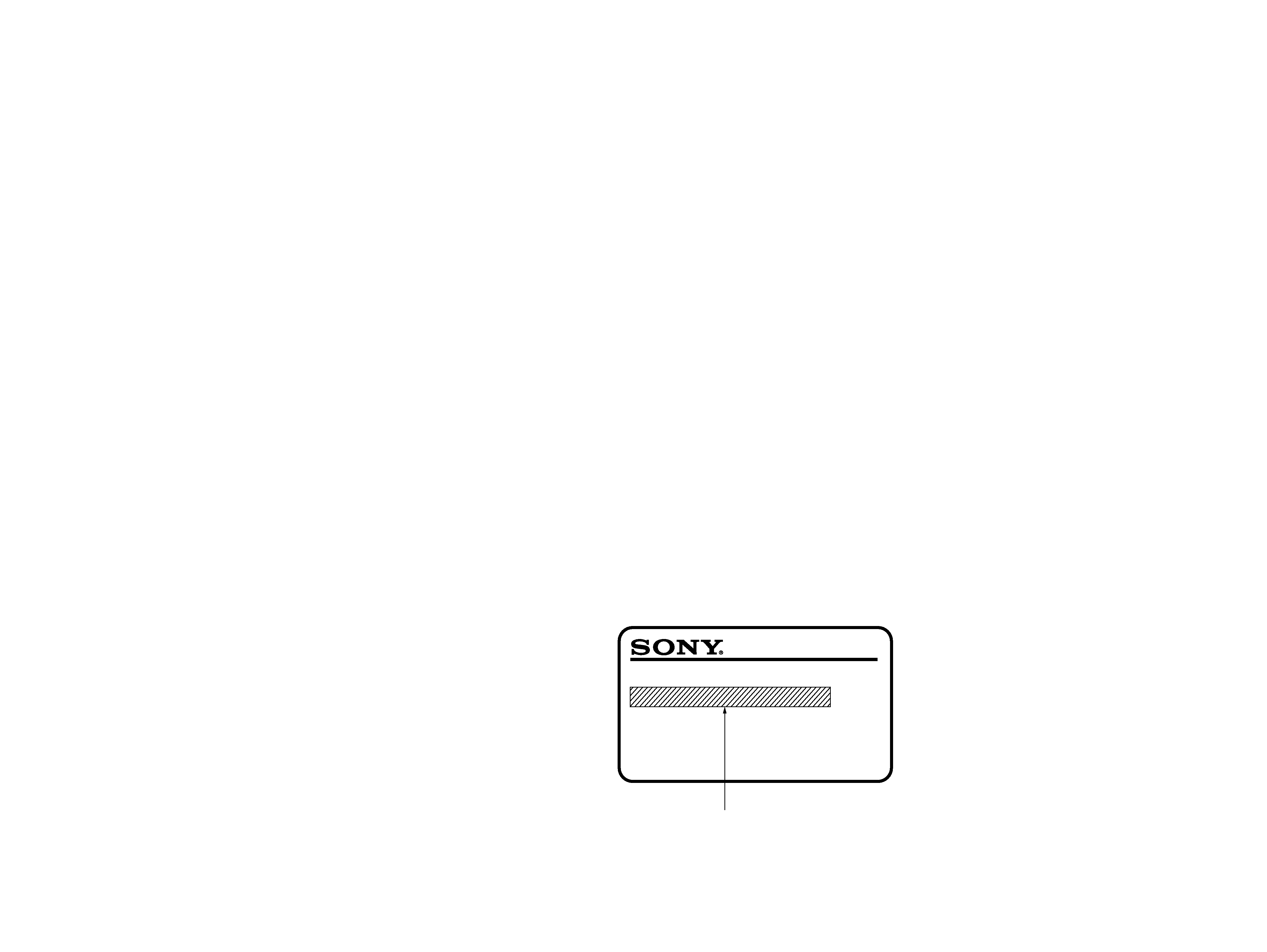
MODEL IDENTIFICATION
-- Model Number Label --
Australian : AC 240V AC, ~ 50/60Hz 170W
Thai : AC 220V AC, ~ 50/60Hz 170W
OTHER MODEL : AC 110-120V, 220-240V selectable
~ 50/60Hz 170W
MODEL IDENTIFICATION
MODEL No.STR-W770
FM STEREO/FM-AM RECEIVER
TABLE OF CONTENTS
1.
GENERAL ······································································ 3
2.
TEST MODE ·································································· 5
3.
DIAGRAMS ···································································· 6
3-1.
Circuit Boards Location ····················································· 6
3-2.
Printed Wiring Board -- Panel Section -- ························· 7
3-3.
Schematic Diagram -- Panel Section -- ··························· 9
3-4.
Printed Wiring Board -- Main Section -- ······················· 12
3-5.
Schematic Diagram -- Main Section -- ·························· 15
3-6.
Printed Wiring Board and Schematic Diagram
-- Power Section -- ························································ 19
3-7.
Printed Wiring Board and Schematic Diagram
-- Mic Echo/AV in Section -- ········································ 23
3-8.
Printed Wiring Board and Schematic Diagram
-- Power Section -- ························································ 26
3-9.
IC Pin Function ································································ 29
3-10. IC Block Diagrams ··························································· 31
4.
EXPLODED VIEWS
4-1.
Main Section ····································································· 33
4-2.
Panel Section ···································································· 34
5.
ELECTRICAL PARTS LIST ··································· 35
General
Power requirements
240V AC, 50/60 Hz (Australian)
220V AC, 50/60 Hz (Thai)
110 - 120V/220-240V AC adjustable, 50/60 Hz
(OTHER MODEL)
Power consumption
170 watts
Dimensions (w / h / d)
Approx. 280
× 205 × 336 mm
Mass
Approx. 7.0 kg
Design and specifications are subject to change without notice.
-- 3 --
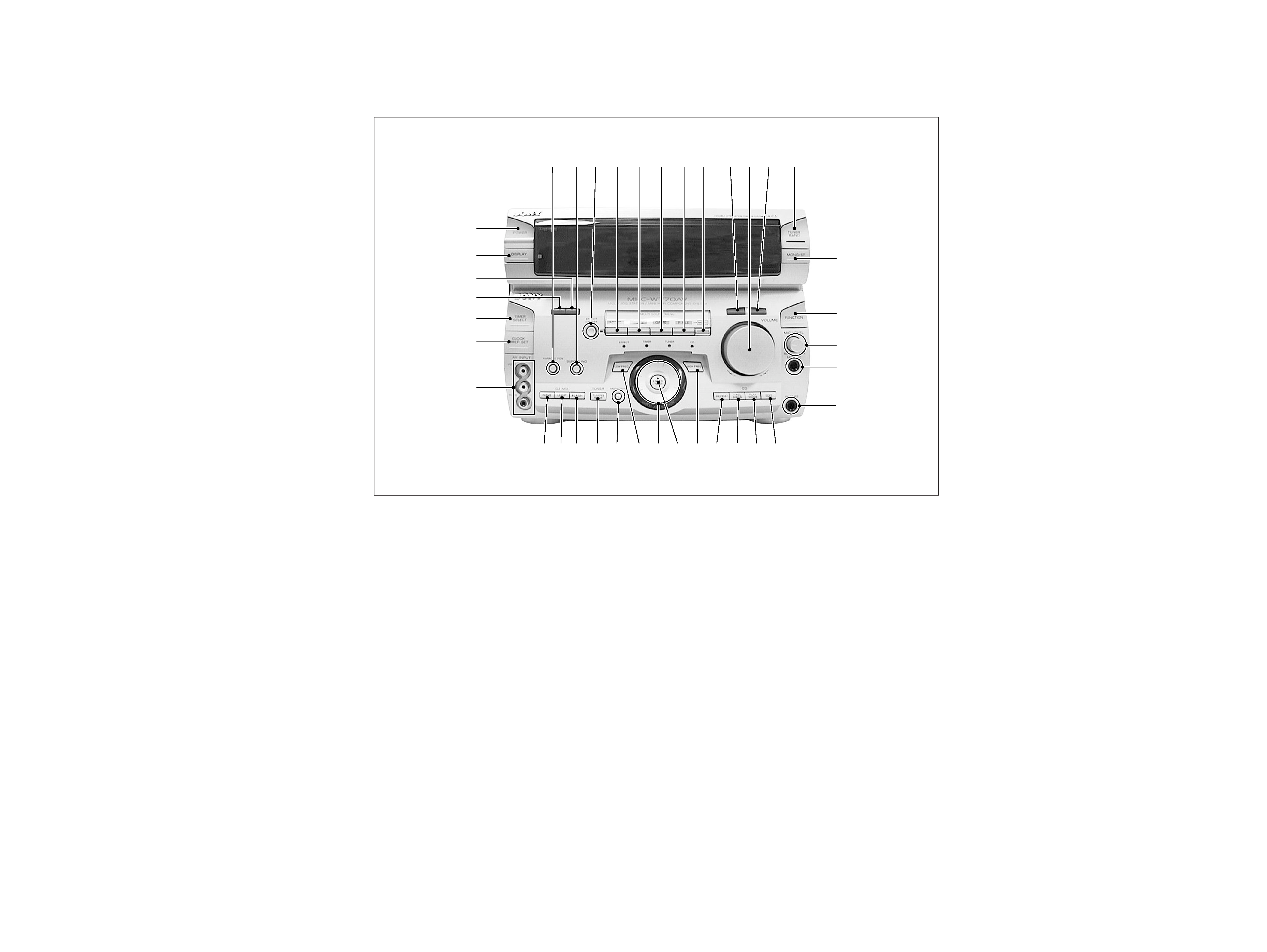
SECTION 1
GENERAL
-- FRONT PANEL --
1 KARAOKE PON/MPX button
2 SURROUND button
3 EFFECT ON/OFF button
4 MUSIC button
5 MOVIE button
6 GAME button
7 P FILE button
8 MEMO button
9 DBFB button
!º VOLUME
!¡ GROOVE button
!TM TUNER BAND button
!£ MONO/ST button
!¢ FUNCTION button
!
MIC LEVEL
!§ MIX MIC jack
!¶ PHONES jack
!· EDIT button
!ª PLAY MODE button
@º 1/ALL DISCS button
@¡ REPEAT button
@TM HIGH FREQ button
@£ ENTER/NEXT button
@¢ MULTI JOG STATION dial
@
LOW FREQ button
@§ MEMORY button
@¶ TUNING MODE button
@· FLASH button
@ª LOOP button
#º WAVE button
#¡ AV INPUT jack
#TM CLOCK TIMER SET button
#£ TIMER SELECT button
#¢ DOLBY PROLOGIC button
#
MODE button
#§ DISPLAY button
#¶ POWER button
1 2 3 4 5 6 7 8 9 !º !¡ !TM
!£
!¢
!
!§
!¶
!·
!ª
@º
@¡
@TM
@£
@§
@¢
@
@¶
@·
@ª
#º
#¡
#TM
#£
#§
#¶
#
#¢
-- 4 --
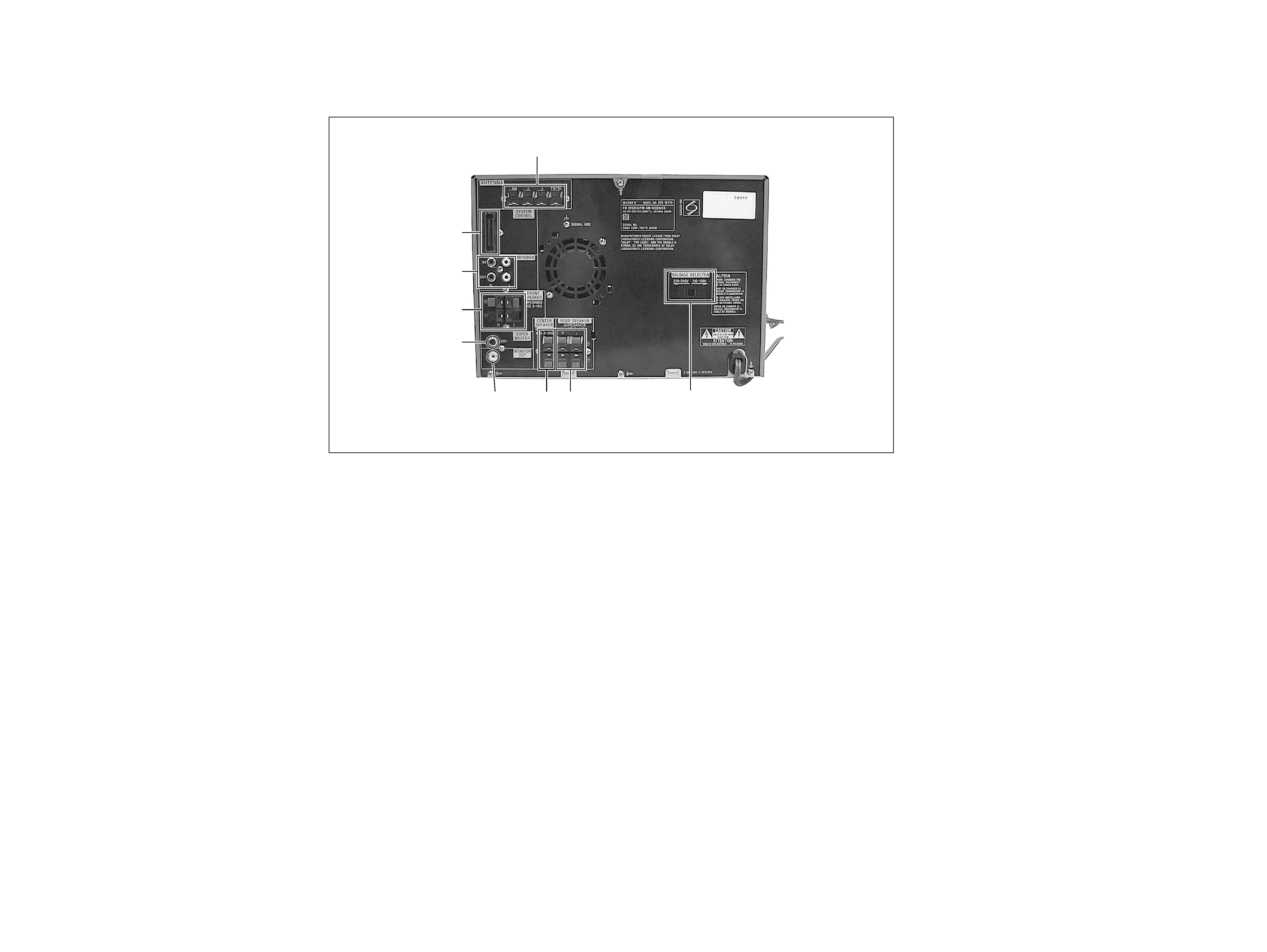
-- BACK PANEL --
#· SYSTEM CONTROL
#ª MD/VIDEO jack
$º FRONT SPEAKER terminal
$¡ SUPER WOOFER jack
$TM MONITOR OUT jack
$£ CENTER SPEAKER terminal
$¢ REAR SPEAKER terminal
$
VOLTAGE SELECTOR switch
(EXCEPT Thai, Australian model)
$§ ANTENNA terminal
Photo : E MODEL
$§
#·
#ª
$º
$¡
$TM
$
$£ $¢
FL DISPLAY/KEY LED TEST MODE
Press the REPEA
T, ENTER/NEXT and SURR OUND b uttons
sim ultaneousl y.
1.
AllFLsegmentsandallLEDsturnon.
2.
Toaccessthemicr
opr ocessorinf
ormation, pressthePFILE
ke y. Eac hpressingofthePFILEke
yad vancesthedispla
yon
theFLtubeinthef
ollo wingsequence
.
3.Toc hec ktheencoder
,presstheMUSICke
y.Thef ollo wingdispla y
appearsontheFLtube.
"K
0J
0V
0"
Then umberafterKindicatesthen
umberoftimesthattheke
yis
pressed.
Theke ywhic hwaspressedinthepast,
isnotcounted.
Theke ywhic hispressedhereafteriscounted.
Pressingan
yke y
increasesthenumberafterK.
ThenumberafterJindicatesthenumberofrotationsthattheJOG
dialisr otated. TurningtheJOGdialc
loc kwiseincreasesthen
umber
after J . Turning the JOG dial counter
-cloc kwise decreases the
numberafterJ.
The n umber after
V indicates the n
umber of r otations that the
VOLUME dial is r otated. Turning the VOLUME dial c loc kwise
increasesthen
umberafter V. Turningthe VOLUMEdialcounter
-
cloc kwisedecreasesthen
umberafter V.
Toe xitthismode ,perf ormthe"ColdReset"(resetc
learingmemor
y)
asdescribedbelo
w.
GENERAL TEST MODE
(INCLUDING AMPLIFIER AND TUNER)
Press the REPEA
T, ENTER/NEXT and CLOCK TIMER SET
buttonssim ultaneousl ywhilethemainpo
werison.
1.
Soundv olumedispla ysegmentstar
tsb linking.
2.
ThetuningentersthePRESETmode.
3.
Rotatingthe
VOLUMEcontr olc loc kwiseincreasesthev
olume
leveltomaxim um.
Rotatingthe
VOLUMEcontr olcounter -cloc kwisedecreases
thev olumele veltominim um.
4.
Pressing the MUSIC ke
y decreases the equaliz
er cur ve to
minim umand"EQCHECK"appear
sonthedispla
y.
Pressing the MO
VIE key increases the equaliz
er cur ve to
maximum.
PressingtheGAMEke
ymakestheequaliz
ercur veflat.
5.
Pressing an
y of the DBFB, GR OOVE or SURR OUND ke y
disappear s"EQCHECK"onthedispla
y.
Toe xitthismode ,perf ormthe"ColdReset"(resetc
learingmemor
y)
asdescribedbelo
w.
SECTION 2
TEST MODE
AGING MODE
1.
CDagingmode
Toe xecutetheCDa
ging, setthethreediscstotheCDtra
yand
set the function to CD
. REPEA T, ENTER/NEXT and LOOP
buttonssim ultaneousl y.TheCDa gingmodestar
tsandthedisc
calendarstartsblinking.
2.
Tapea gingmode
Toe xecutethetapea
ging, setthetw otapestothetapeAandB
drives. Setthefunctionto
TAPE. PresstheREPEA
T, ENTER/
NEXTandLOOPb uttonssim ultaneousl y.PresstheAf
orwar d
ke y to star t the tape a ging mode . "AGING" appear s on the
displa y.
CD SERVICE MODE
Turn on the main po
wer .Press the REPEA
T, ENTER/NEXT and
KARAOKEPON/MPXb uttonssim ultaneousl y.
VACStog glesbetweenONandOFF
.
VACS LEVEL DISPLAY
Turn on the main po
wer . Press the EDIT
, ENTER/NEXT and
KARAOKEPON/MPXb uttonssim ultaneousl y.
VACSle velappear sonthedispla
y.
CD SHIP MODE
Turn on the main po
wer . Press the PLA
Y MODE and PO WER
buttonssim ultaneousl y.
Themainpo weristurnedoffandLOCKappear
sonthedispla
y.
TUNER STEP CHANGE
Turnonthemainpo
wer . Setthefunctionto
TUNER. SelectMW
bandfromthepresenttuning.
Turn off the main po
wer . Press the ENTER/NEXT and PO
WER
buttons sim ultaneousl y. The main po wer is turned on and the
chang edstepappear
sonthedispla
y.
MD/VIDEO 1 FUNCTION CHANGE
PresstheFUNCTIONandPO
WERb uttonssim ultaneousl ywhile
the main po wer is on. When the function is set to
VIDEO 1, the
functionisc hang edtoMDandMDappear
sonthedispla
y.
WhenthefunctionissettoMD
,thefunctionisc
hang edto VIDEO
1and VIDEO1appear sonthedispla
y.
COLD RESET (Reset which clears memory.)
Press the REPEA
T, ENTER/NEXT and DISPLA Y buttons
sim ultaneousl y at an y time . The system is reset while c
learing
memor y.
HOT RESET
(Reset which does not clear memory.)
Press the REPEA
T,ENTER/NEXT and TIMER SELECT b uttons
sim ultaneousl yatan ytime . Thesystemisresetwithoutc
learing
memor y.
STR microprocessor version number
HCD microprocessor version number
VCD microprocessor version number (VCD model only)
Model name
Destination
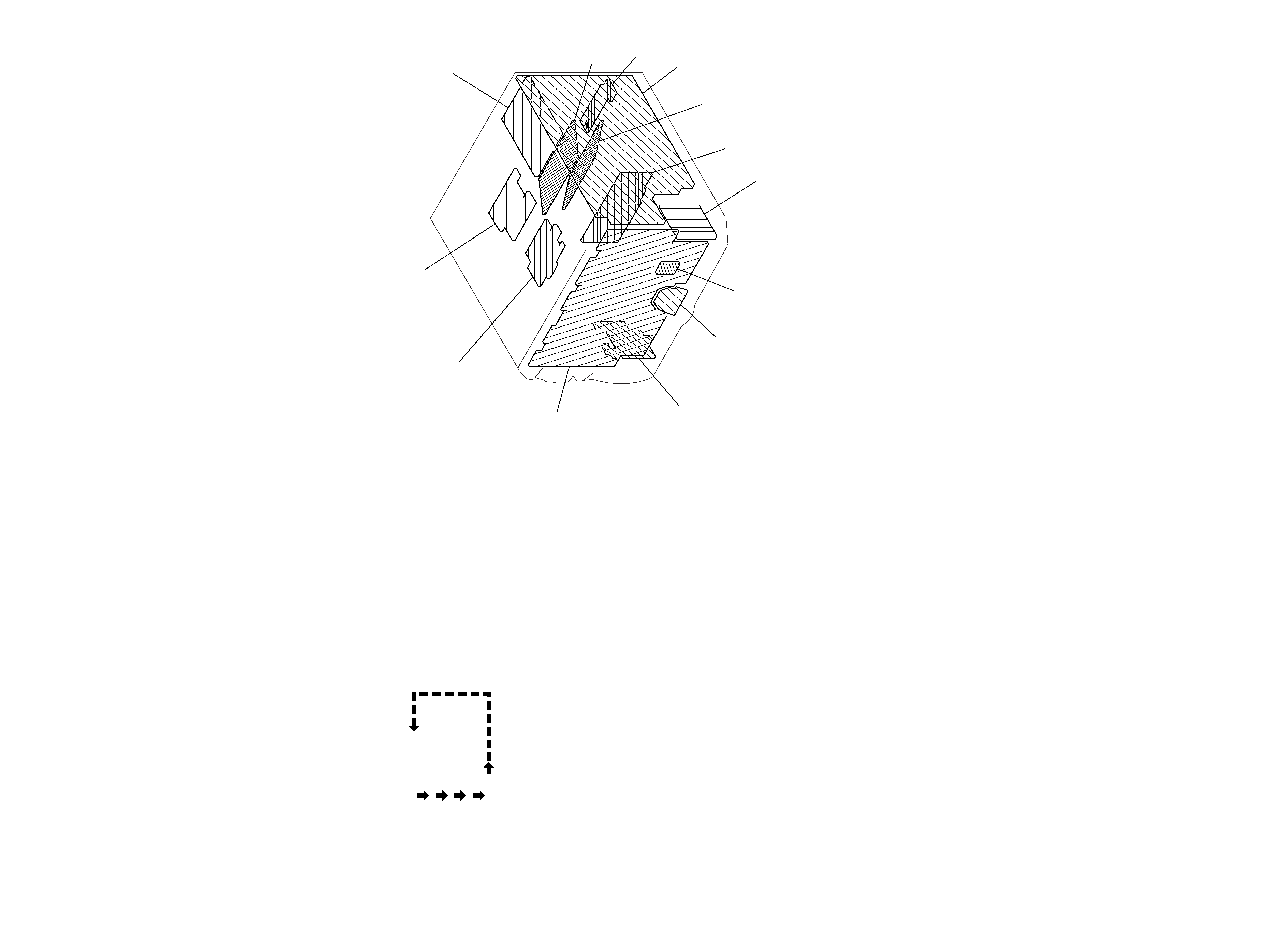
3-1.
CIRCUIT BOARDS LOCATION
SECTION 3
DIAGRAMS
PRI BOARD
SEC BOARD
PANEL BOARD
AVIN BOARD
JOG BOARD
VOLUME BOARD
MIC ECHO BOARD
AMP-A BOARD
MAIN BOARD
SUR BOARD
SURROUND
AMP BOARD
ENCAPSULATED
COMPONENT
-- 5 --
-- 6 --
SUPPLY BOARD