MICROFILM
SERVICE MANUAL
STR-W55 is RECEIVER section in
MHC-W55.
AEP Model
UK Model
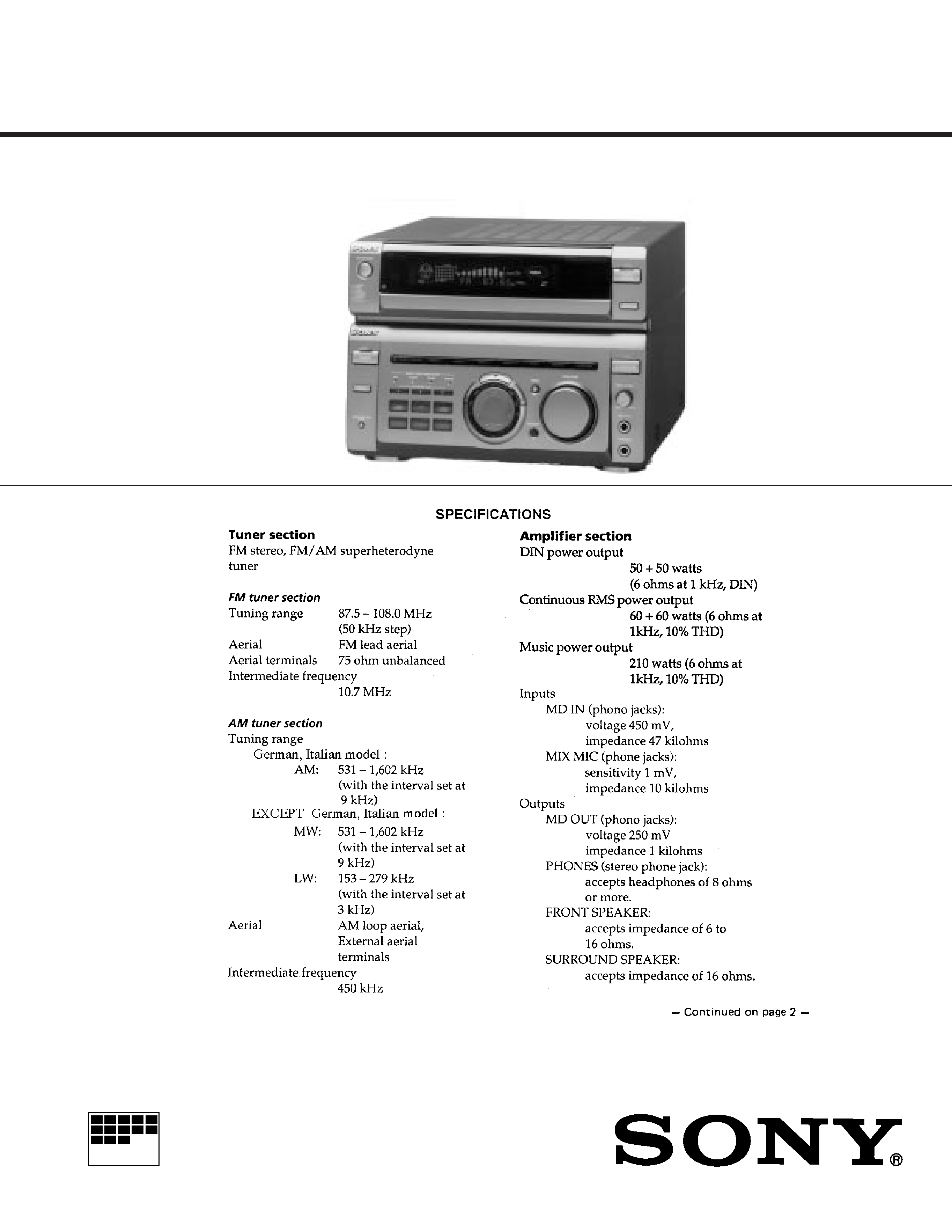
STR-W55
FM STEREO/FM-AM RECEIVER
2
Specifications ................................................................................... 1
1.
GENERAL ............................................................................... 3
2.
TEST MODE ........................................................................... 4
3.
ELECTRICAL ADJUSTMENTS .......................................... 5
4.
EXPLANATION OF IC TERMINALS .................................. 6
5.
DIAGRAMS
5-1. Printed Wiring Boards Main Section .......................... 10
5-2. Schematic Diagram Main Section .............................. 13
5-3. Schematic Diagram Panel Section ............................. 18
5-4. Printed Wiring Boards Panel Section ......................... 21
5-5. Schematic Diagram TCB Section ............................... 23
5-6. Printed Wiring Boards TCB Section .......................... 25
6.
EXPLODED VIEWS
6-1. Chassis Section ................................................................ 26
6-2. Front Panel Section ......................................................... 27
7.
ELECTRICAL PARTS LIST ............................................... 28
Section
Title
Page
TABLE OF CONTENTS
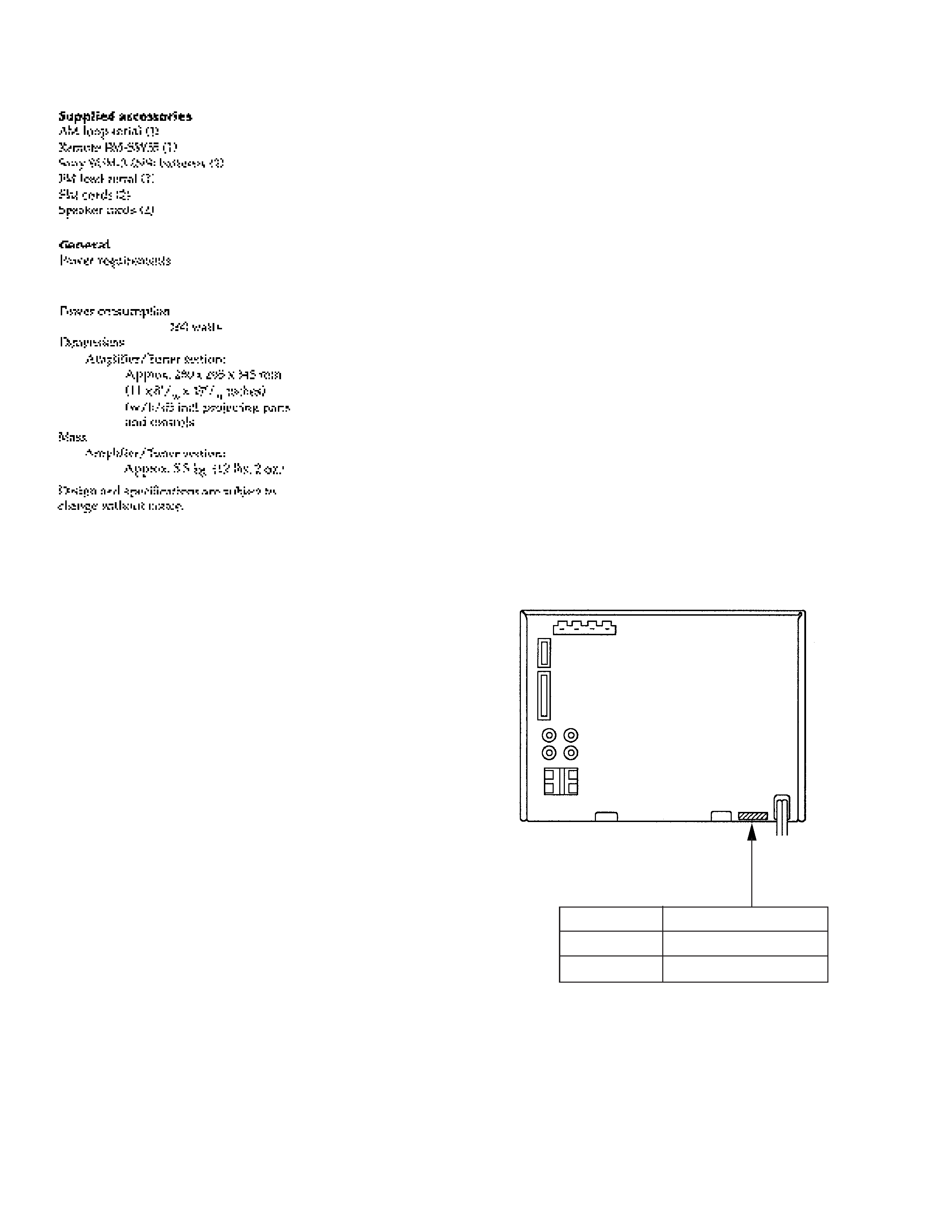
MODEL INDENTIFICATION
BACK PANEL
Parts No.
Model
4-978-033-6
UK
4-978-033-2
AEP, German, Italian, AED
r
Abbreviation
AED : Norway, Sweden, Finland, Denmark
Notes on chip component replacement
· Never reuse a disconnected chip component.
· Notice that the minus side of a tantalum capacitor may be damaged
by heat.
SAFETY-RELATED COMPONENT WARNING!!
COMPONENTS IDENTIFIED BY MARK
! OR DOTTED LINE WITH
MARK
! ONTHE SCHEMATIC DIAGRAMS AND INTHE PARTS LIST
ARE CRITICAL TO SAFE OPERATION.
REPLACE THESE COMPONENTSWITH SONY PARTS WHOSE PART
NUMBERS APPEAR AS SHOWN IN THIS MANUAL OR IN
SUPPLEMENTS PUBLISHED BY SONY.
220-230V AC, 50/60Hz (EXCEPT UK)
220-240V AC, 50/60Hz (UK)
3
SECTION 1
GENERAL
This section is extracted from
instruction manual.

4
SECTION 2
TEST MODE
DISPLAY / KEY TEST MODE
Press the ENTER/NEXT and FUNCTION buttons simultaneously.
Then press the MENU 1 button with the following 4 seconds to set the Test Mode.
1. The message "W1 J (destination) " appears on the screen and a 32 cycle square wave of the subcrystal oscillator is output from Pin 24
(AUB. OUT).
2. Press any key to rotate JOG and all FL indicators light up.
When you rotate JOG at this point, the display changes as follows.
N all FL indicators on Nn FL pattern 1 Nn FL pattern 2 n
The changes and all LED indicators light up.
3. Again press any key to set the key count check. The following display appears.
00
0
The numbers in order from left to right show ; the number of keys pressed, the JOG count (1 click per 4 counts), and the VOL count.
(1 cycle is a count of 96.)
4. Press the Power button to reset to the factory settings.
AMP TEST MODE
Press the ENTER/NEXT and FUNCTION buttons simultaneously.
Then press the MENU 2 button with the following 4 seconds to set the Test Mode.
1. The message "AMP TEST" appears on the screen. Press the MENU button to call up the Equalizer Curve for the Amp Test.
However when the function is set to the tuner, use the MENU button to call up each tuner preset from 1 through 5.
2. Press the Power button to reset to the factory settings.
MICROCOMPUTER COLD START
Press the ENTER/NEXT and FUNCTION buttons simultaneously.
Then press the MENU 3 button with the following 4 seconds to reset the microcomputer to the factory settings.
SUBCRYSTAL TEST MODE
Press the ENTER/NEXT and FUNCTION buttons simultaneously.
Then press the MENU 4 button with the following 4 seconds.
The message "XTAL TEST " appears on the screen and a 32 cycle square wave of the subcrystal oscillator is output from Pin 24 (AUB.OUT).
In addition, a square wave of the same frequency as the subcrystal oscillator, is output from 4PIN (POWER. ON/OFF).
Press the Power button to reset to the factory settings.
5
SECTION 3
ELECTRICAL ADJUSTMENTS
Precautions in Repairing
Note. 1 :
The adjustment should be performed in the publication.
(AM
nFM)
Note. 2 :
As a front-end (FE1) is difficult to repair if faulty, replace it
with new one.
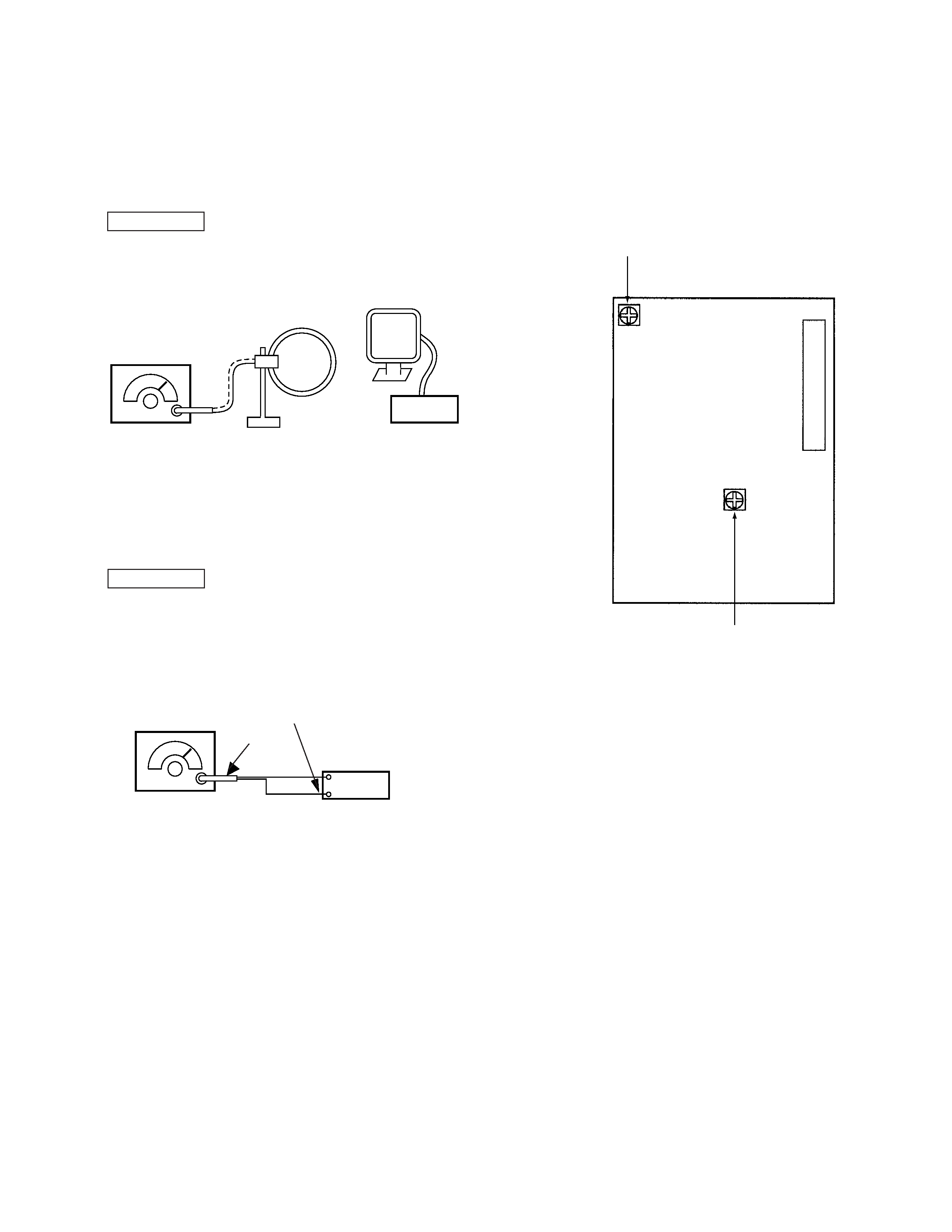
AM SECTION
AM Tuned Indication Lighting Level
Setting :
Band :AM ( MW)
set
AM RF signal
generator
Carrier frequency : 999kHz
loop antenna B
loop antenna A
Procedure :
1. Set loop antenna A so that the loop antenna B input level becomes
55dB
µ/m (0.6mV/m).
2. Tune the set to 999kHz .
3. Adjust RV41 so that the TUNED indicator goes on.
FM SECTION
FM Tuned Indication Lighting Level
Note :
Always make the tuning level adjustment first.
(Since it affects the FM tuning level.)
Setting :
Band : FM
set
FM RF stereo signal
generator
FM ANTENNA terminal
Carrier frequency : 98MHz
Modulation
: OFF
Output level
:0.018mV (25dB
µ)
75
coaxial
Procedure :
1. Tune the set to 98MHz.
2. Adjust RV42 so that the TUNED indicator goes on.
Adjustment Location : TCB board
Adjustment Location :
[ TCB BOARD ] Component side
RV42 : FM Tuned Indication Lighting Level
RV41 : AM Tuned Indication Lighting Level
FE1