3-864-512-51(1)
FM Stereo
FM-AM Receiver
© 1998 by Sony Corporation
STR-V55ES
Operating Instructions
GB
C2
C1

2GB
WARNING
To prevent fire or shock
hazard, do not expose the
unit to rain or moisture.
Precautions
On safety
Should any solid object or liquid fall into
the cabinet, unplug the receiver and have it
checked by qualified personnel before
operating it any further.
On power sources
· Before operating the receiver, check that
the operating voltage is identical with
your local power supply. The operating
voltage is indicated on the nameplate at
the rear of the receiver.
· The unit is not disconnected from the AC
power source (mains) as long as it is
connected to the wall outlet, even if the
unit itself has been turned off.
· If you are not going to use the receiver
for a long time, be sure to disconnect the
receiver from the wall outlet. To
disconnect the AC power cord, grasp the
plug itself; never pull the cord.
· AC power cord must be changed only at
the qualified service shop.
On placement
· Place the receiver in a location with
adequate ventilation to prevent heat
buildup and prolong the life of the
receiver.
· Do not place the receiver near heat
sources, or in a place subject to direct
sunlight, excessive dust or mechanical
shock.
· Do not place anything on top of the
cabinet that might block the ventilation
holes and cause malfunctions.
On operation
Before connecting other components, be
sure to turn off and unplug the receiver.
On cleaning
Clean the cabinet, panel and controls with
a soft cloth slightly moistened with a mild
detergent solution. Do not use any type of
abrasive pad, scouring powder or solvent
such as alcohol or benzine.
If you have any question or problem
concerning your receiver, please
consult your nearest Sony dealer.
3GB
About This Manual
The instructions in this manual are for model STR-V55ES.
Check your model number by looking at the upper right
corner of the front panel.
Conventions
· The instructions in this manual describe the controls on
the receiver. You can also use the controls on the
supplied remote if they have the same or similar names
as those on the receiver. For details on the use of your
remote, refer to the separate operating instructions
supplied with the remote.
· The following icon is used in this manual:
z Indicates hints and tips for making the task easier.
This receiver incorporates the Dolby
* Pro Logic Surround
system and the DTS** Digital Surround System.
* Manufactured under license from Dolby Laboratories Licensing
Corporation. DOLBY, the double-D symbol a, "PRO LOGIC,"
and Dolby Digital (AC-3) are trademarks of Dolby Laboratories
Licensing Corporation.
**Manufactured under license from Digital Theater Systems, Inc. US
Pat. No. 5,451,942 and other worldwide patents issues and pending.
"DTS" and "DTS Digital Surround" are trademarks of Digital
Theater Systems, Inc. © 1996 Digital Theater Systems, Inc. All
rights reserved.
TABLE OF CONTENTS
Hooking Up the Components
4
Unpacking 4
Antenna Hookups 5
Audio Component Hookups 6
Video Component Hookups 7
Digital Component Hookups 8
Other Hookups 10
Hooking Up and Setting Up the
Speaker System
12
Speaker System Hookup 13
Multi-Channel Surround Setup 14
Before You Use Your Receiver 19
Location of Parts and Basic Amplifier
Operations
22
Front Panel Parts Description 22
Enjoying Surround Sound
26
Selecting a Sound Field 27
Understanding the Multi-Channel Surround
Displays 31
Customizing Sound Fields 33
Receiving Broadcasts
37
Direct Tuning 38
Automatic Tuning 39
Preset Tuning 39
Other Operations
41
Indexing Preset Stations and Program Sources 42
Recording 42
Using the Sleep Timer 43
Adjustments Using the SET UP Button 43
Additional Information
44
Troubleshooting 44
Specifications 46
Glossary 48
Tables of Settings Using the CURSOR MODE and
SET UP buttons 49
Index 51
To view the demonstration
Hold down SET UP and press
1/u to turn on the power.
The following message appears in the display twice:
"Now Demonstration Mode!! If you finish
demonstration, please press POWER KEY while
this message appears in the display. Thank you!!"
To cancel the demonstration
Press
1/u to turn the receiver off during the previous
message. The next time you turn the receiver on, the
demonstration will not appear.
Note
Running the demonstration will clear the receiver's
memory. For details on what will be cleared, see "Clearing
the receiver's memory" on page 19.
GB

4GB
Hooking Up
the
Components
This chapter describes how to connect
various audio and video components
to the receiver. Be sure to read the
sections for the components you have
before you actually connect them to
the receiver.
Unpacking
Check that you received the following items with the
remote:
· FM wire antenna (1)
· AM loop antenna (1)
· Remote commander RM-TP501 (remote) (1)
· LR6 (size-AA) alkaline batteries (4)
Inserting batteries into the remote
Insert four size-AA (LR6) alkaline batteries with the + and
properly oriented in the battery compartment. When
using the remote, point it at the remote sensor g on the
receiver.
For details, refer to the operating instructions supplied
with your remote.
z When to replace batteries
Under normal conditions, the batteries should last for about 3
months. When the remote no longer operates the receiver,
replace all batteries with new ones.
Notes
· Do not leave the remote in an extremely hot or humid place.
· Do not use new batteries with old ones.
· Do not mix battery types. This remote is designed for use with
alkaline batteries only.
· Do not expose the remote sensor to direct sunlight or lighting
apparatuses. Doing so may cause a malfunction.
· If you don't use the remote for an extended period of time,
remove the batteries to avoid possible damage from battery
leakage and corrosion.
Before you get started
· Turn off the power to all components before making
any connections.
· Do not connect the AC power cords until all of the
connections are completed.
· Be sure to make connections firmly to avoid hum and
noise.
· When connecting an audio/video cord, be sure to
match the color-coded pins to the appropriate jacks on
the components: yellow (video) to yellow; white (left,
audio) to white; and red (right, audio) to red.
5GB
Hooking
Up
the
Components
+
RL
R
LRL
SPEAKERS
IMPEDANCE USE 416
CENTER
REAR
FRONT
BA
S-VIDEO
IN
VIDEO
S-VIDEO
OUT
VIDEO
S-VIDEO
OUT
VIDEO
S-VIDEO
IN
VIDEO
S-VIDEO
OUT
VIDEO
DVD
DVD IN
COAXIAL
S-VIDEO
IN
VIDEO
IN
L
R
REC OUT
SIGNAL GND
AM
AUDIO
IN
L
R
L
R
AUDIO
OUT
AUDIO
IN
AUDIO
OUT
AUDIO
IN
CTRL A1
FRONT
REAR
WOOFER
CENTER
y
y
ANTENNA
TAPE
VIDEO 2
TV/LD
DVD
S-LINK
S-VIDEO
IN
VIDEO
AUDIO
IN
DIGITAL
VIDEO 1
MONITOR
PRE OUT
AC OUTLET
IN
PHONO
IN
CD
IN
REC OUT
MD/DAT
FM
75
COAXIAL
TV/LD IN OPT
CD IN OPT
MD/DAT OUT OPT
MD/DAT IN OPT
4
8
IMPEDANCE
SELECTOR
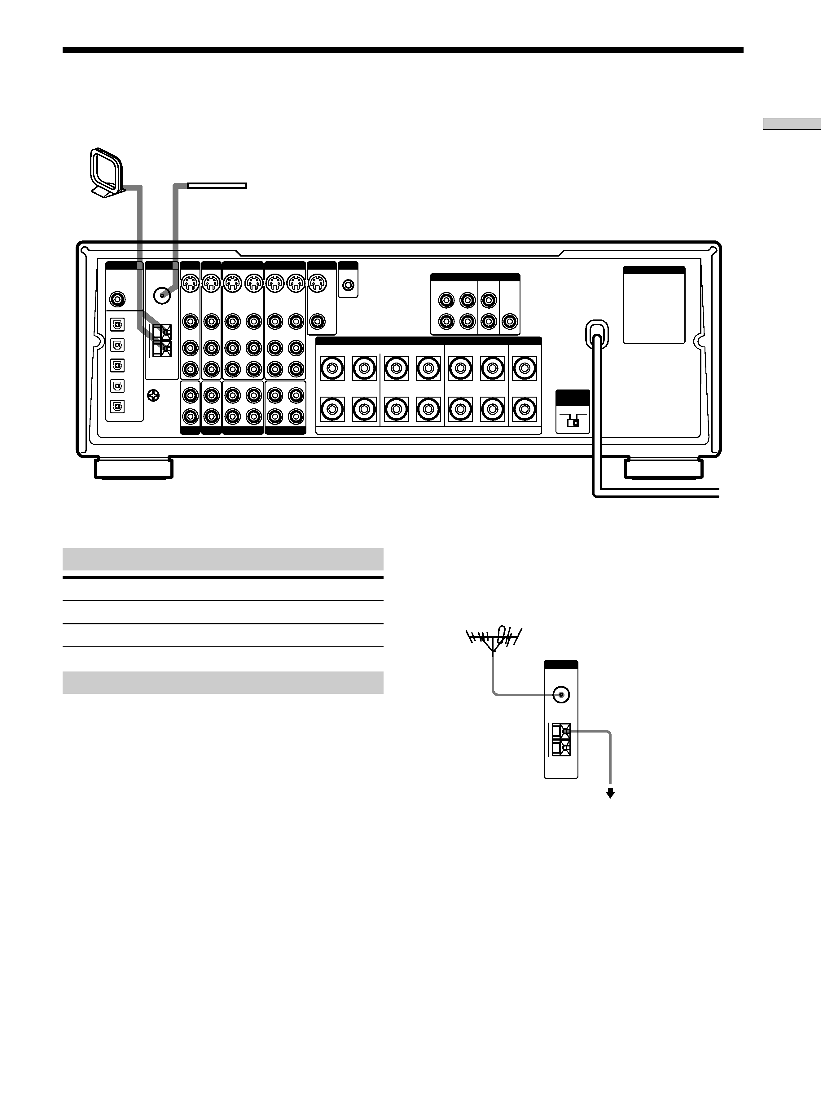
FM wire antenna
(supplied)
AM loop antenna
(supplied)
Important
If you connect the receiver to an outdoor antenna, ground
it against lightning. To prevent a gas explosion, do not
connect the ground wire to a gas pipe.
Note
Do not use the SIGNAL GND
y terminal for grounding the
receiver.
Terminals for connecting the antennas
Connect the
To the
AM loop antenna
AM terminals
FM wire antenna
FM 75
COAXIAL terminal
Notes on antenna hookups
· To prevent noise pickup, keep the AM loop antenna
away from the receiver and other components.
· Be sure to fully extend the FM wire antenna.
· After connecting the FM wire antenna, keep it as
horizontal as possible.
Antenna Hookups
Ground wire
(not supplied)
To ground
AM
y
ANTENNA
FM
75
COAXIAL
Receiver
Outdoor FM antenna
z If you have poor FM reception
Use a 75-ohm coaxial cable (not supplied) to connect the receiver
to an outdoor FM antenna as shown below.