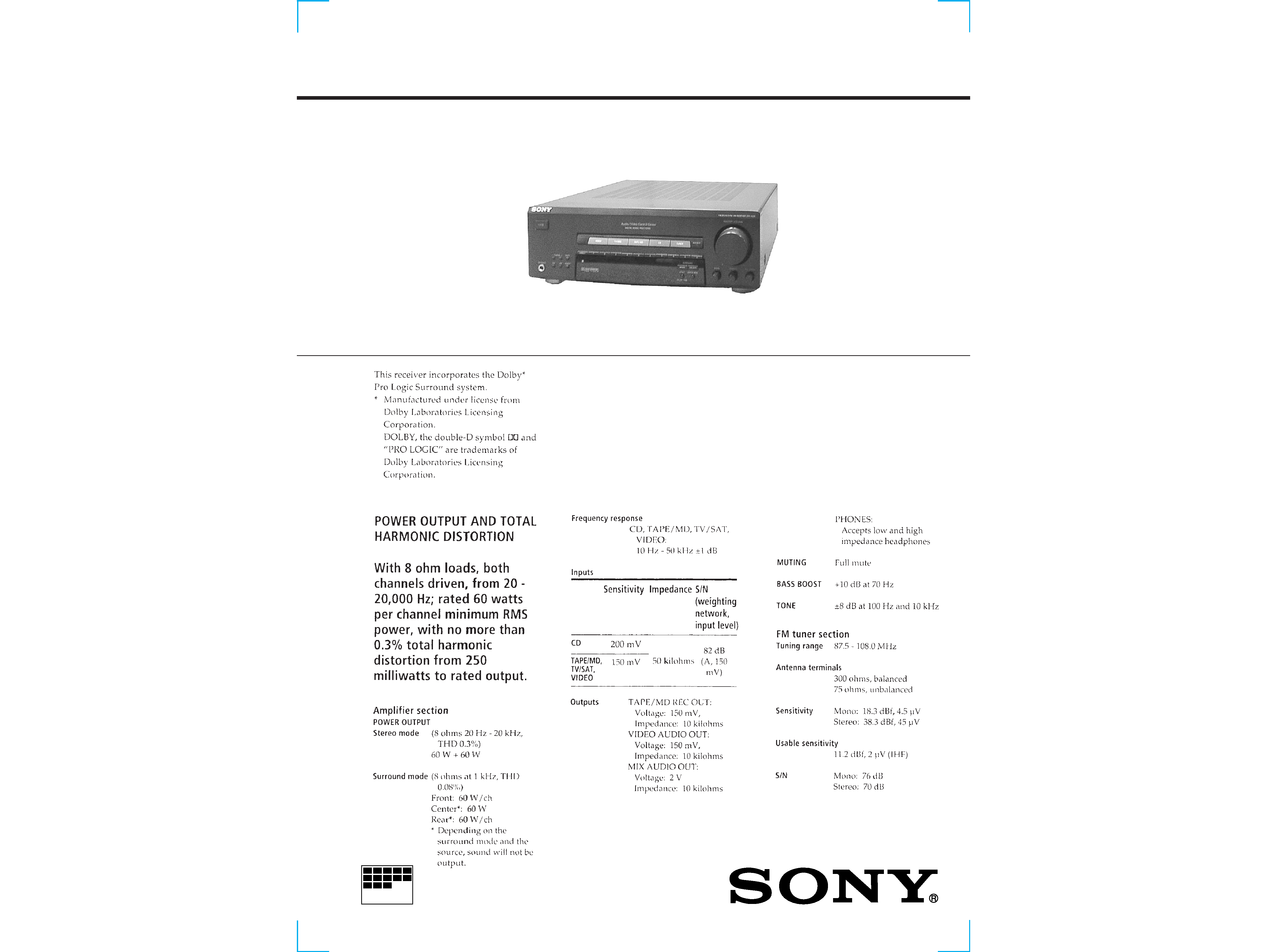
1
MICROFILM
US Model
SPECIFICATIONS
SERVICE MANUAL
FM STEREO/FM-AM RECEIVER
STR-V220
-- Continued on next page --
2
SAFETY-RELATED COMPONENT WARNING !!
COMPONENTS IDENTIFIED BY MARK
! OR DOTTED LINE
WITH MARK
! ON THE SCHEMATIC DIAGRAMS AND IN
THE PARTS LIST ARE CRITICAL TO SAFE OPERATION.
REPLACE THESE COMPONENTS WITH SONY PARTS
WHOSE PART NUMBERS APPEAR AS SHOWN IN THIS
MANUAL OR IN SUPPLEMENTS PUBLISHED BY SONY.
Notes on chip component replacement
· Never reuse a disconnected chip component.
· Notice that the minus side of a tantalum capacitor may be
damaged by heat.
SAFETY CHECK-OUT
After correcting the original service problem, perform the follow-
ing safety checks before releasing the set to the customer:
Check the antenna terminals, metal trim, "metallized" knobs, screws,
and all other exposed metal parts for AC leakage. Check leakage as
described below.
LEAKAGE
The AC leakage from any exposed metal part to earth Ground and
from all exposed metal parts to any exposed metal part having a
return to chassis, must not exceed 0.5 mA (500 microampers). Leak-
age current can be measured by any one of three methods.
1. A commercial leakage tester, such as the Simpson 229 or RCA
WT-540A. Follow the manufacturers' instructions to use these
instruments.
2. A battery-operated AC milliammeter. The Data Precision 245
digital multimeter is suitable for this job.
3. Measuring the voltage drop across a resistor by means of a VOM
or battery-operated AC voltmeter. The "limit" indication is 0.75
V, so analog meters must have an accurate low-voltage scale.
The Simpson 250 and Sanwa SH-63Trd are examples of a pas-
sive VOM that is suitable. Nearly all battery operated digital
multimeters that have a 2V AC range are suitable. (See Fig. A)
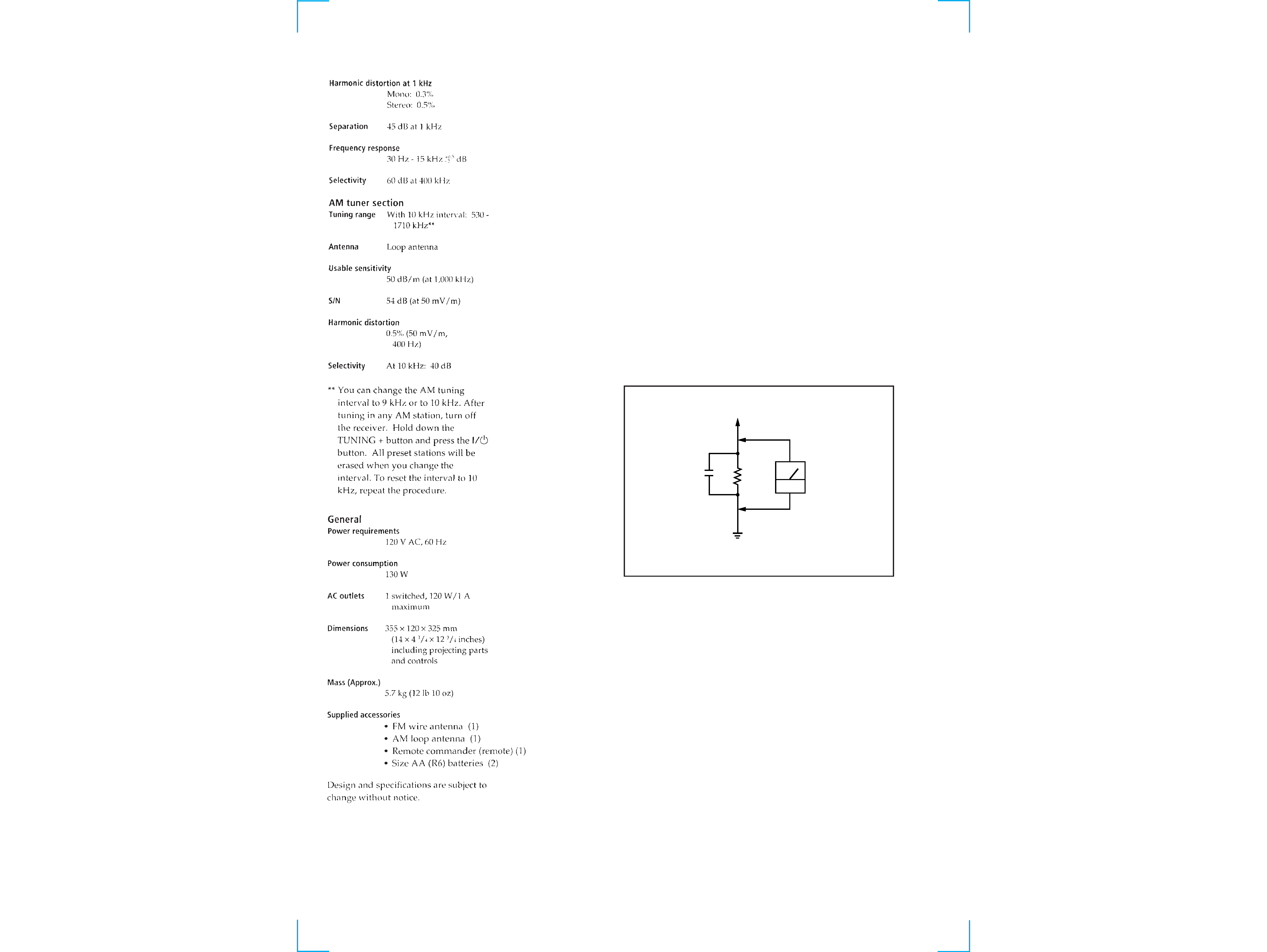
Fig. A. Using an AC voltmeter to check AC leakage.
0.15
µF
To Exposed Metal
Parts on Set
1.5k
AC
voltmeter
(0.75V)
Earth Ground

3
TABLE OF CONTENTS
SECTION 1
SERVICING NOTE
1. SERVICING NOTE .......................................................... 3
2. GENERAL .......................................................................... 4
3. ELECTRICAL BLOCK CHECKING ...................... 5
4. DIAGRAMS
4-1. Circuit Boards Location ........................................................ 6
4-2. Schematic Diagram Main (1/3) Section .......................... 7
4-3. Schematic Diagram Main (2/3) Section .......................... 9
4-4. Schematic Diagram Main (3/3) Section ........................ 11
4-5. Printed Wiring Board Main Section .............................. 13
FACTORY SET
Mode which sets the preset settings of the unit to that at shipment.
Procedure:
While pressing the VIDEO button and TV/SAT button together, press the
1/u button to turn on the power.
"FACTORY" will be displayed and factory settings executed.
INITIALIZATION
Mode which erases all the preset settings of the unit.
Use this mode when returning the unit to the customer.
Procedure:
While pressing the VIDEO button, TV/SAT button, and TAPE/MD button together, press the
1/u button to turn on the power.
"INITIAL" will be displayed and initialization executed.
FLUORESCENT INDICATOR TUBE LIGHTING CHECK
Mode which lights up the whole fluorescent indicator tube or partially.
Procedure:
While pressing the TV/SAT button and TAPE/MD button together, press the
1/u button to turn on the power.
The fluorescent indicator tube will light up in about 0.5 seconds, and then start to light up partially. After partial lighting completes, the
BASS BOOST indicator will light up, "FINISH" will be displayed, indicating that fluorescent indicator tube lighting check has completed.
SWITCHING OF 9 kHz/10 kHz AM CHANNEL STEP
The AM channels of this unit can be switched between 9 kHz and 10 kHz.
Procedure:
Set FUNCTION to AM and turn off the power.
While pressing the TUNING + button, press the
1/u button to turn on the power.
"9 k STEP" or "10 k STEP" will be displayed, and the channel step will be switched.
4-6. Printed Wiring Board Display Section .......................... 15
4-7. Schematic Diagram Display Section ............................ 17
4-8. Schematic Diagram Panel Section ................................ 19
4-9. Printed Wiring Board Panel Section .............................. 21
4-10. IC Block Diagrams ........................................................... 23
4-11. IC Pin Functions ............................................................... 26
5. EXPLODED VIEWS
5-1. Case Section ........................................................................ 28
5-2. Chassis Section ................................................................... 29
6. ELECTRICAL PARTS LIST ........................................ 30
4
Front Panel Descriptions
SECTION 2
GENERAL
Location of Parts and Controls
1
1/u button
2 VIDEO button
3 TV/SAT button
4 TAPE/MD button
5 CD button
6 TUNER button
7 BASS BOOST indicator
8 MASTER VOLUME knob
9 BALANCE knob
78
2
3
46
5
1
16
17
10
11
13
14
15
12
9
18
19
21
22
23
24
25
20
10 TREBLE knob
11 BASS knob
12 SURROUND ON/OFF button
13 CENTER MODE button
14 EFFECT/DELAY TIME button
15 SURROUND MODE button
16 Numeral (1 to 0) button
17 Display window
18 DIRECT button
19 SHIFT button
20 MEMORY button
21 AM button
22 TUNING + button
23 FM button
24 TUNING button
25 PHONES jack
This section is extracted from
instruction manual.
STR-V220
SECTION 4
DIAGRAMS
4-1. CIRCUIT BOARDS LOCATION
THIS NOTE IS COMMON FOR PRINTED WIRING
BOARDS AND SCHEMATIC DIAGRAMS.
(In addition to this, the necessary note is printed
in each block.)
For schematic diagrams.
Note:
· All capacitors are in µF unless otherwise noted. pF: µµF
50 WV or less are not indicated except for electrolytics
and tantalums.
· All resistors are in
and 1/4 W or less unless otherwise
specified.
·
¢
: internal component.
· 2 : nonflammable resistor.
· C : panel designation.
For printed wiring boards.
Note:
· X : parts extracted from the component side.
· b : Pattern of the conductor side.
· U : B+ Line.
· V : B Line.
· Voltages and waveforms are dc with respect to ground
under no-signal (detuned) conditions.
no mark : FM
WAVEFORMS
1
2
IC201 #¢ X1
IC301 #TM
Note: The components identified by mark
! or dotted line
with mark
! are critical for safety.
Replace only with part number specified.
· Indication of transistor
C
These are omitted
E
B
8MHz
4.8Vp-p
4.19MHz
5.4Vp-p
Caution:
Pattern face side:
Parts on the pattern face side seen from
(Conductor Side)
the pattern face are indicated.
Parts face side:
Parts on the parts face side seen from
(Component Side)
the parts face are indicated.
· Voltages are taken with a VOM (Input impedance 10 M
).
Voltage variations may be noted due to normal produc-
tion tolerances.
· Waveforms are taken with a oscilloscope.
Voltage variations may be noted due to normal produc-
tion tolerances.
· Circled numbers refer to waveforms.
· Signal path.
F
: FM
SECONDARY board
PRIMARY board
STANDBY board
MAIN board
VOL-TONE board
DISPLAY board
PHONE JACK board
KEY board
MAIN (1/3) SECTION
DISPLAY SECTION
5
6
SECTION 3
ELECTRICAL BLOCK CHECKING
ADJUSTING THE FM/SD SIGNAL SENSITIVITY
Setting:
oscilloscope
Main board
TP (IC501 6 pin)
Procedure:
1. Set the SSG output level to 26 dB and input the signal.
2. Adjust SFR501 so that the oscilloscope level becomes 0V.
3. Raise the SSG output level slightly (max. 35 dB) when the ad-
justment in step 2 fails, and repeat steps 1 and 2.
NOTE: If the adjustment cannot be performed even when set to 35
dB, the sensitivity may be faulty, etc. Check the antenna
terminal connection, FM front end and IF circuit, etc. and
perform adjustments again.
FM ANTENNA (75
)
FM RF SSG
Set
Carrier frequency: 98 MHz
Modulation:
AUDIO 1 kHz,
75 kHz deviation (100%)
Output level:
26 dB (at 75
open) (MAX 35 dB)