FM Stereo
FM-AM Receiver
Operating Instructions
4-235-542-11(1)
STR-SL7
© 2001 Sony Corporation
Owner's Record
The model and serial numbers are located on the rear panel. Record the serial number
in the space provided below. Refer to them whenever you call upon your Sony dealer
regarding this product.
Model No.
Serial No.
2
WARNING
To prevent fire or shock hazard, do not
expose the unit to rain or moisture.
Don't throw a battery, dispose it as
the injurious wastes.
This symbol is intended to alert the user to
the presence of uninsulated "dangerous
voltage" within the product's enclosure that
may be of sufficient magnitude to constitute
a risk of electric shock to persons.
This symbol is intended to alert the user to
the presence of important operating and
maintenance (servicing) instructions in the
literature accompanying the appliance.
WARNING
This equipment has been tested and found to comply
with the limits for a Class B digital device, pursuant
to Part 15 of the FCC Rules. These limits are
designed to provide reasonable protection against
harmful interference in a residential installation. This
equipment generates, uses, and can radiate radio
frequency energy and, if not installed and used in
accordance with the instructions, may cause harmful
interference to radio communications. However, there
is no guarantee that interference will not occur in a
particular installation. If this equipment does cause
harmful interference to radio or television reception,
which can be determined by turning the equipment
off and on, the user is encouraged to try to correct the
interference by one or more of the following
measures:
Reorient or relocate the receiving antenna.
Increase the separation between the equipment and
receiver.
Connect the equipment into an outlet on a circuit
different from that to which the receiver is
connected.
Consult the dealer or an experienced radio/TV
technician for help.
CAUTION
You are cautioned that any changes or modifications
not expressly approved in this manual could void
your authority to operate this equipment.
Demonstration Mode
The demonstration will activate the first time you
turn on the power. When the demonstration starts,
the following message appears in the display
twice:
"NOW DEMONSTRATION MODE IF YOU
FINISH DEMONSTRATION PLEASE PRESS
POWER KEY WHILE THIS MESSAGE
APPEARS IN THE DISPLAY THANK YOU"
To cancel the demonstration
Press ?/1 to turn the receiver off during the
previous message. The next time you turn the
receiver on, the demonstration will not appear.
To view the demonstration
Hold down SET UP and press ?/1 to turn on the
power.
Notes
· Running the demonstration will clear the
receiver's memory. For details on what will be
cleared, see "Clearing the receiver's memory"
on page 13.
· There will be no sound when the demonstration
mode is activated.
· You cannot cancel demonstration if you did not
press ?/1 while the above message is being
displayed. To cancel demonstration after the
above message appears, press ?/1 twice to
activate the demonstration again. Then, press
?/1 while the above message is being
displayed.
Note to CATV system installer
This reminder is provided to call the CATV system
installer's attention to Article 820-40 of the NEC that
provides guidelines for proper grounding and, in
particular, specifies that the cable ground shall be
connected to the grounding system of the building, as
close to the point of cable entry as practical.
This receiver incorporates Dolby* Digital and Pro
Logic Surround and the DTS** Digital Surround
System.
* Manufactured under license from Dolby
Laboratories.
"Dolby", "Pro Logic" and the double-D symbol are
trademarks of Dolby Laboratories.
** "DTS" and "DTS Digital Surround" are registered
trademarks of Digital Theater Systems, Inc.
Tip
The instructions in this manual describe the controls
on the receiver. You can also use the controls on the
supplied remote if they have the same or similar
names as those on the receiver. For details on the use
of your remote, see pages 3336.

3
Table of Contents
Parts Identification
Main unit ............................................... 4
Hooking Up the Components
Required cords ....................................... 5
Antenna hookups ................................... 6
Video component hookups .................... 7
Digital component hookups ................... 8
Multi channel input hookups ................. 9
Other hookups ..................................... 10
Hooking Up and Setting Up
the Speaker System
Speaker system hookups ..................... 11
Performing initial setup operations ..... 13
Multi channel surround setup .............. 13
Checking the connections .................... 18
Basic Operations
Selecting the component ..................... 18
Enjoying Surround Sound
Selecting a sound field ........................ 19
Understanding the multi channel
surround displays .......................... 21
Customizing sound fields .................... 22
Receiving Broadcasts
Manual memory .................................. 24
Automatic memory .............................. 24
Tuning to preset stations ...................... 25
Automatic tuning ................................. 25
Direct tuning ........................................ 25
Other Operations
Using the Sleep Timer ......................... 26
Adjustments using the SET UP button ... 26
Additional Information
Precautions .......................................... 27
Troubleshooting ................................... 27
Specifications ...................................... 29
Tables of settings using LEVEL/SURR
and SET UP buttons ...................... 31
Adjustable parameters for each sound
field ............................................... 32
Before you use your remote ................ 33
Remote button description ................... 33
Changing the factory setting of
a function button ............. Back cover
4
AUX 6 (18)
Cursor buttons (
U/u) qh (14, 22
26)
Display qk (21)
DVD 3 (18)
LEVEL/SURR qj (22, 23)
MASTER VOLUME qa (17, 18)
MEMORY/ENTER qf (24)
MULTI CH IN 8 (18)
MULTI CHANNEL DECODING
indicator 5
MUTING qd (18)
PHONES jack ql (18)
SET UP q; (14, 26)
SOUND FIELD +/ qs (19, 23)
TUNER 9 (25)
TUNER FM/AM 7 (18, 24, 25)
TV 4 (18)
VIDEO 2 (18)
?/1 (power) 1 (13, 17, 18, 23)
+/ qg (14, 2226)
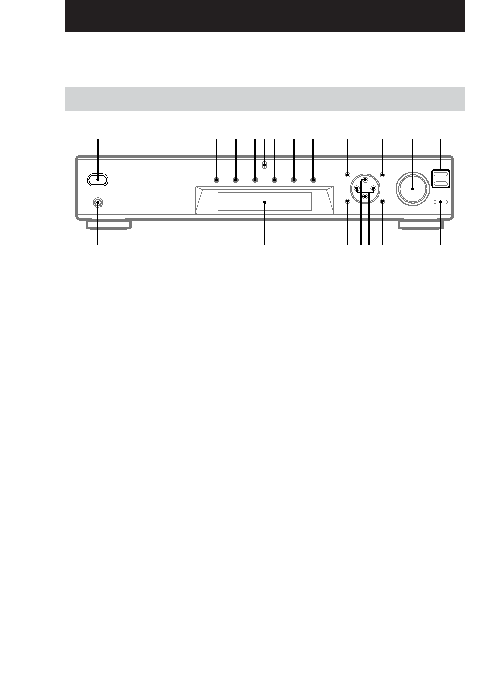
Parts Identification
Main unit
The items are arranged in alphabetical order.
Refer to the pages indicated in parentheses ( ) for details.
1
2
3 456 7
8
9
0
qa
qs
ql
qk
qj
qf
qg
qh
qd
5
Hooking
Up
the
Components
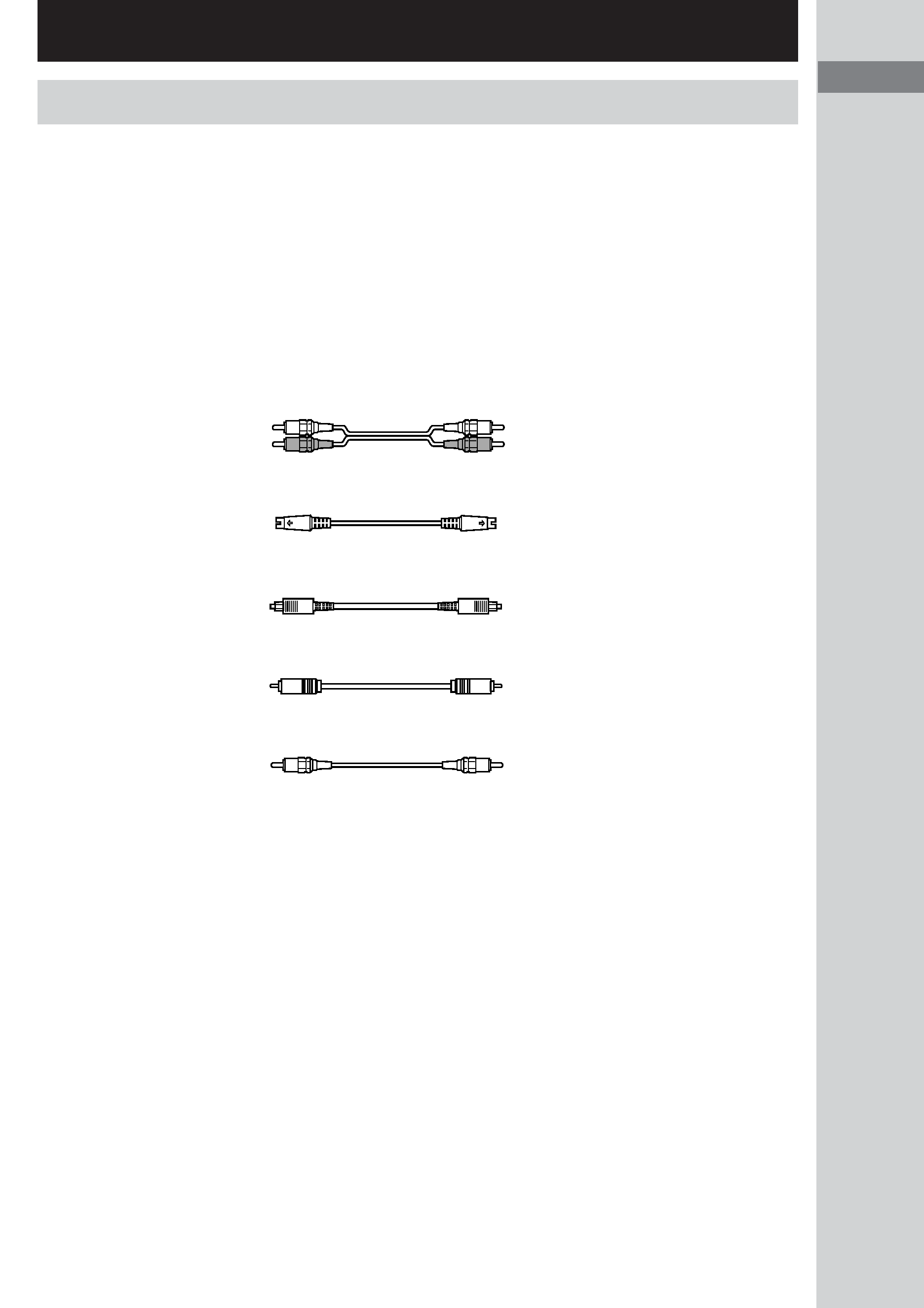
Required cords
Before you get started
· Turn off the power to all components before making any connections.
· Do not connect the AC power cord until all of the connections are completed.
· Be sure to make connections firmly to avoid hum and noise.
· When connecting optical digital cords, take the caps off the connectors and insert the cord plugs straight
in until they click into place.
· Do not bend or tie the optical digital cord.
A Audio cord (not supplied)
White (L)
White (L)
Red (R)
Red (R)
B S-video cord (not supplied)
Yellow (video)
Yellow (video)
C Optical digital cord (not supplied)
Black
Black
D Coaxial digital cord (supplied)
Orange
Orange
E Monaural audio cord (not supplied)
Black
Black
Hooking Up the Components
5
Parts
Identification/Hooking
Up
the
Components