1
SERVICE MANUAL
TUNER/AMPLIFIER
AEP Model
UK Model
E Model
SPECIFICATIONS
STR-NX5MD
STR-NX5MD is the
Tuner and Amplifier
Section in DHC-NX5MD.
Amplifier section
European model
DIN power output (rated) 80 + 80 watts
(6 ohms at 1 kHz, DIN)
Continuous RMS power output (reference)
100 + 100 watts
(6 ohms at 1 kHz, 10% THD)
Music power output (reference)
160 + 160 watts
(6 ohms at 1 kHz, 10% THD)
Other models
DIN power output (rated) 90 + 90 watts
(6 ohms at 1 kHz, DIN)
Continuous RMS power output (reference)
110 + 110 watts
(6 ohms at 1 kHz, 10% THD)
Inputs
VIDEO IN:
voltage 250 mV
(phono jacks)
impedance 47 kilohms
TAPE IN:
voltage 250 mV
(phono jacks)
impedance 47 kilohms
Outputs
TAPE OUT:
voltage 250 mV
(phono jacks)
impedance 1 kilohms
PHONES:
accepts headphones of 8 ohms or
(stereo mini jack)
more
FRONT SPEAKER:
accepts impedance of 6 to 16 ohms
REAR SPEAKER:
accepts impedance of 16 ohms
SUPER WOOFER:
voltage 1 V, impedance 1 kilohms
Tuner section
FM stereo, FM/AM superheterodyne tuner
FM tuner section
Tuning range
Tourist model:
76.0 108.0 MHz
Other models:
87.5 108.0 MHz
Aerial
FM lead aerial
Aerial terminals
75 ohm unbalanced
Intermediate frequency
10.7 MHz
AM tuner section
Tuning range
European models:
531 1,602 kHz
(with the interval set at 9 kHz)
Other models:
531 1,602 kHz
(with the interval set at 9 kHz)
530 1,710 kHz
(with the interval set at 10 kHz)
Aerial
AM loop aerial
Aerial terminals
External aerial terminal
Intermediate frequency
450 kHz
General
Power requirements
European models:
230 V AC, 50/60 Hz
Other models:
120 V, 220 V or 230 240 V AC,
50/60 Hz Adjustable with voltage
selector
Power consumption
European models:
190 watts
Other models:
220 watts
Dimensions (w/h/d)
Approx. 225
× 202 × 356 mm
Mass
European models:
Approx. 7.8 kg
Other models:
Approx. 7.6 kg
Supplied accessories:
AM loop aerial (1)
Remote Commander (1)
Batteries (2)
FM lead aerial (1)
Speaker cords (2)
Front speaker pads (8)
Design and specifications are subject to change
without notice.
2
TABLE OF CONTENTS
1. GENERAL .......................................................................... 3
2. DISASSEMBLY
2-1. Case ....................................................................................... 5
2-2. Front Panel Assy ................................................................... 5
2-3. Back Panel Assy .................................................................... 6
2-4. Main Board ........................................................................... 6
3. TEST MODE ........................................................................ 7
4. DIAGRAMS
4-1. Notes for Printed Wiring Boards and Schematic Diagrams .. 9
4-2. Schematic Diagram Main Board (1/3) .......................... 10
4-3. Schematic Diagram Main Board (2/3) .......................... 11
4-4. Schematic Diagram Main Board (3/3) .......................... 12
4-5. Printed Wiring Board Main Board ................................ 13
4-6. Printed Wiring Board PA Board .................................... 14
4-7. Schematic Diagram PA Board ...................................... 15
4-8. Printed Wiring Board Panel Section ............................. 16
4-9. Schematic Diagram Panel Section ................................ 17
4-10. Printed Wiring Board Transformer Section ................. 18
4-11. Schematic Diagram Transformer Section ................... 19
4-12. IC Pin Function Description ............................................. 20
5. EXPLODED VIEW
5-1. General Section ................................................................... 22
5-2. Front Panel Section ............................................................. 23
5-3. Chassis Section ................................................................... 24
6. ELECTRICAL PARTS LIST ........................................ 25
SAFETY-RELATED COMPONENT WARNING!!
COMPONENTS IDENTIFIED BY MARK 0 OR DOTTED
LINE WITH MARK 0 ON THE SCHEMATIC DIAGRAMS
AND IN THE PARTS LIST ARE CRITICAL TO SAFE
OPERATION. REPLACE THESE COMPONENTS WITH
SONY PARTS WHOSE PART NUMBERS APPEAR AS
SHOWN IN THIS MANUAL OR IN SUPPLEMENTS PUB-
LISHED BY SONY.
MODEL
PART No.
AEP, UK, G, AED and CIS models
4-221-391-8[]
Malaysia and Singapore models
4-221-391-9[]
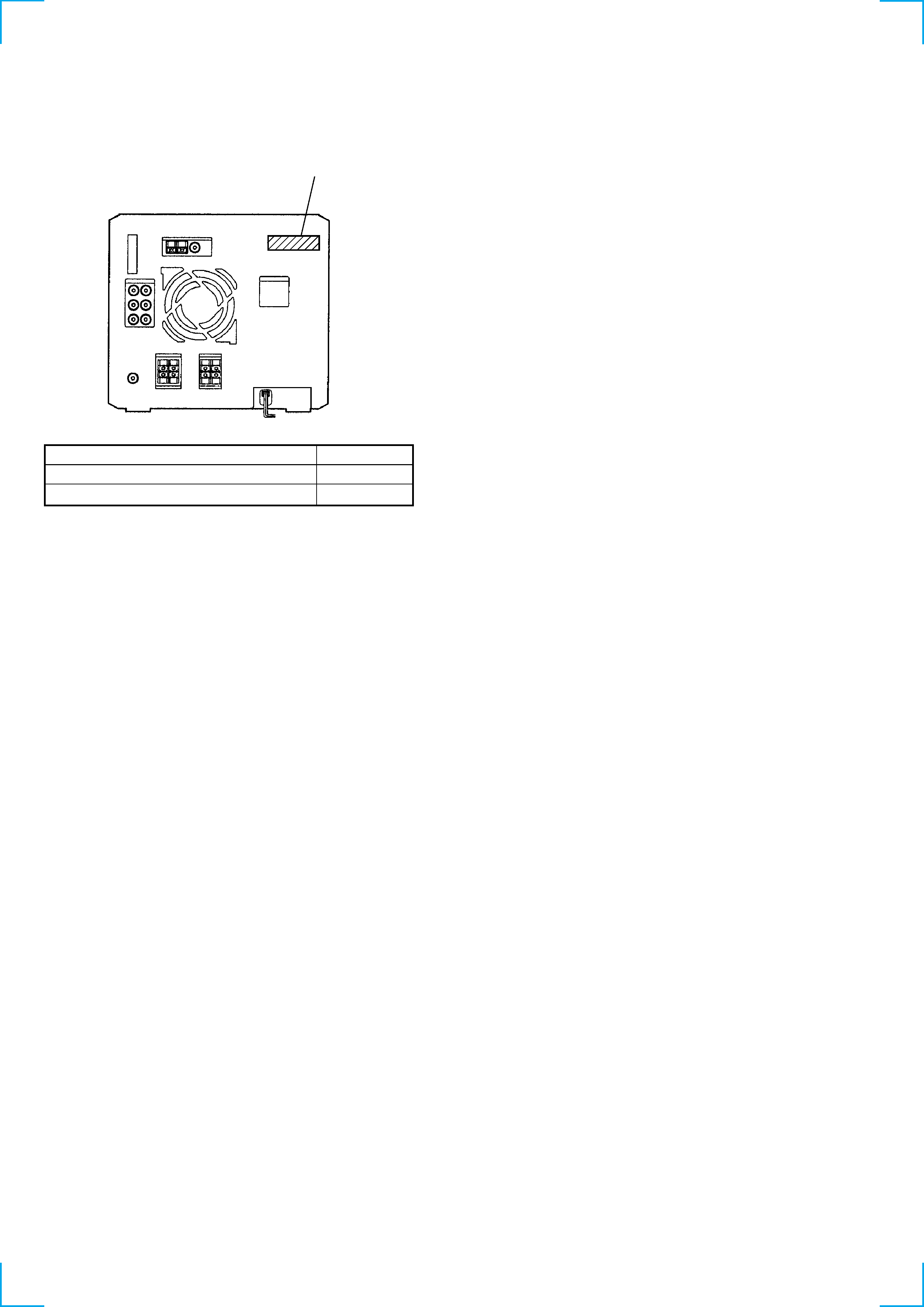
· MODEL IDENTIFICATION
Rear Panel
PART No.
· Abbreviation
G
: German model
AED
: North European model
3
SECTION 1
GENERAL
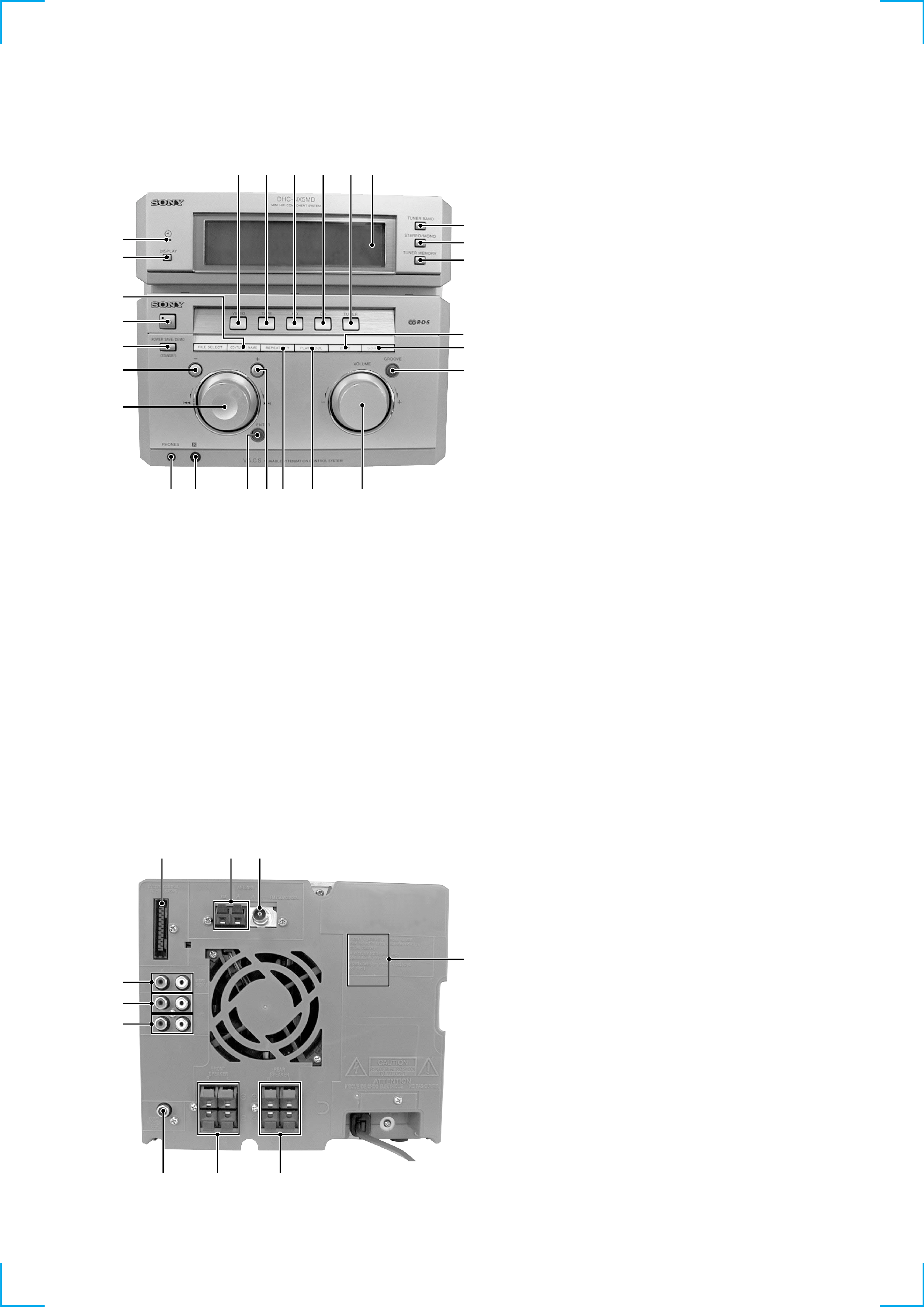
· LOCATION OF CONTROLS
Front Panel
Rear Panel
1 ?/1 (Power) button and indicator
2 CD/TUNER NAME button
3 DISPLAY button
4 TIMER indicator
(AEP, UK, German, AED and CIS models)
5 VIDEO button
6 TAPE button
7 MD button
8 CD button
9 TUNER button
q; Display window
qa TUNER BAND button
qs STEREO/MONO button
qd TUNER MEMORY button
qf DBFB button
qg SURROUND button
qh GROOVE button and indicator
qj VOLUME knob
qk PLAY MODE button
ql REPEAT/PTY button
w; + M button
wa ENTER button and indicator
ws Remote sensor
wd PHONES jack
wf Jog dial
wg m button
wh POWER SAVE/DEMO (STANDBY) button
wj FILE SELECT button
1 SYSTEM CONTROL terminals
2 AM ANTENNA terminals
3 FM ANTENNA terminal
4 VOLTAGE SELECTOR switch
(Malaysia and Singapore models)
5 REAR SPEAKER terminals
6 CENTER SPEAKER terminals
7 SUPER WOOFER OUT jack
8 MD OUT jacks
9 MD IN jacks
q; VIDEO (AUDIO) jacks
9
8
0
1
2
3
4
6
5
7
1
2
wh
wf
wg
4
qs
5
6
7
8
9 0
3
qa
qd
qh
qj
qk
ql
ws
wd
w;
wa
qf
qg
Photo: AEP model
· Abbreviation
AED : North European model
4
This section is extracted from
instruction manual.
7
Getting
Started
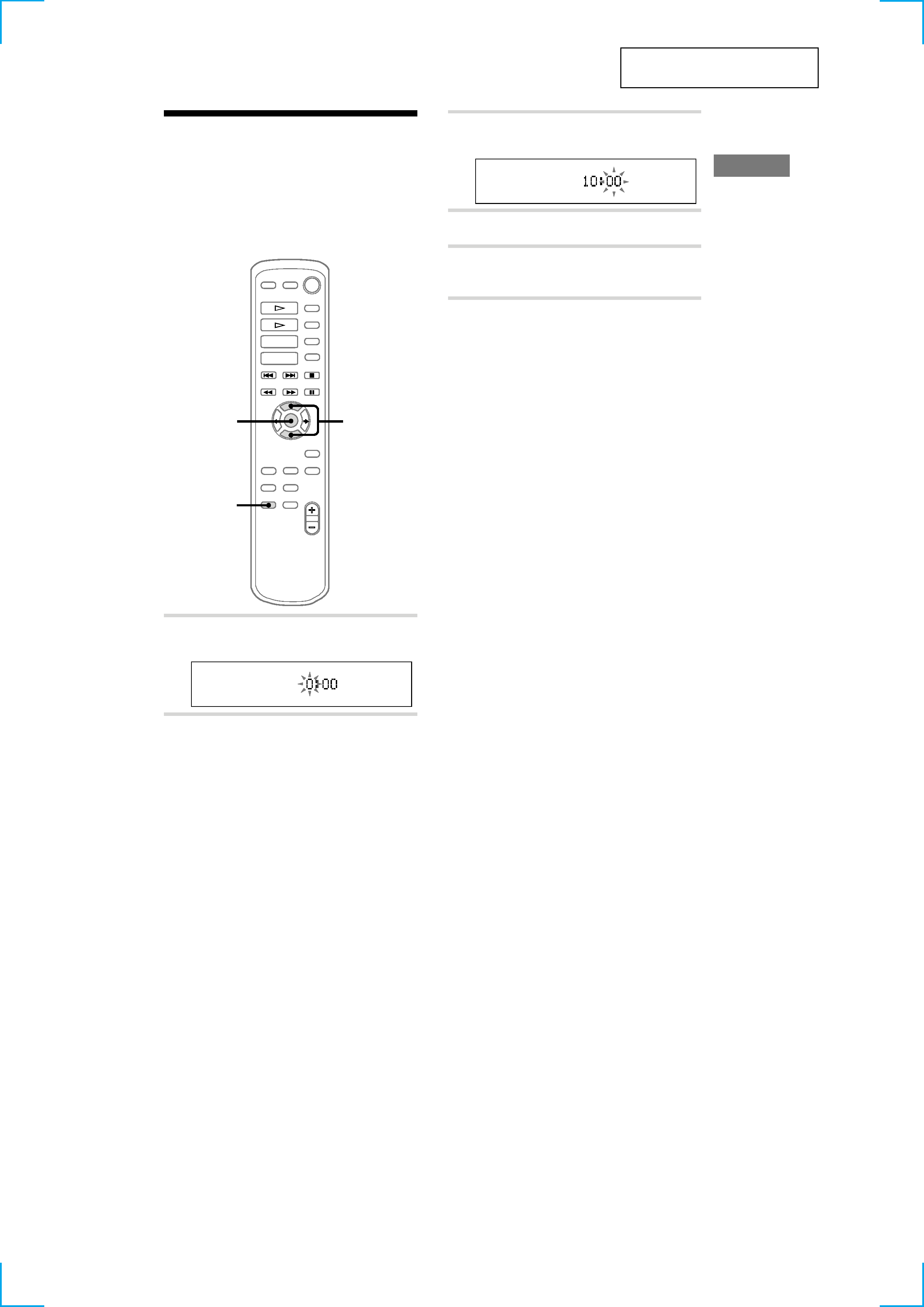
Step 2: Setting the time
You must set the time beforehand to use the timer
functions.
The clock is on a 24-hour system for the European
model, and a 12-hour system for other models.
The 24-hour system is used for illustration
purposes.
1
3,5
2,4
1 Press CLOCK/TIMER SET.
The hour indication flashes.
2 Press V or v to set the hour.
3 Press ENTER.
The minute indication flashes.
4 Press V or v to set the minute.
5 Press ENTER.
The clock starts.
Tips
· If you've made a mistake, start over from step 1.
· Setting the time deactivates the demo mode.
If you want to display the demo mode, press
DISPLAY (European model) or DEMO
(STANDBY) (other models) when the power is off.
To change the time
The previous explanation shows you how to set
the time while the power is off. To change the
time while the power is on, do the following:
1 Press CLOCK/TIMER SET.
2 Press V or v to select the SET CLOCK.
3 Press ENTER.
4 Perform steps 2 through 5 above.
Note
The clock settings are cancelled when you disconnect
the mains lead or if a power failure occurs.
5
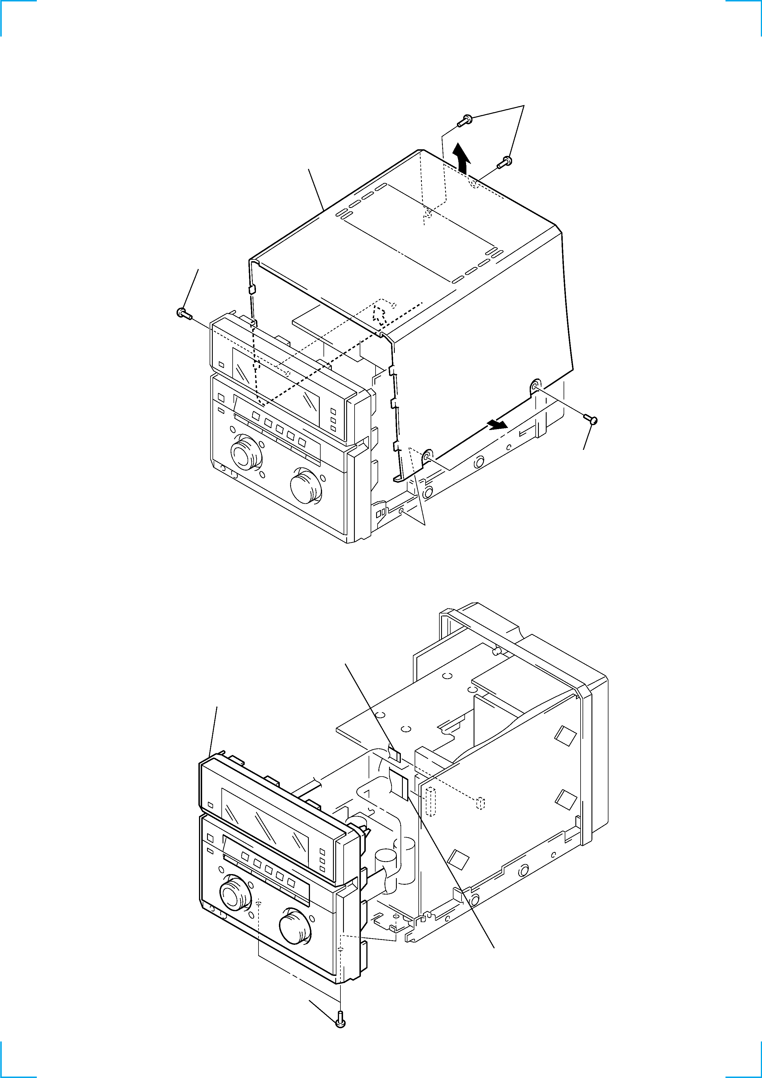
2-1. CASE
2-2. FRONT PANEL ASSY
Note: Follow the disassembly procedure in the numerical order given.
SECTION 2
DISASSEMBLY
3
case
1
two screws
(case 3 TP2)
2
two screws
(BVTP3
× 10)
1
two screws
(case 3 TP2)
3
two screws
(BVTT3
× 6)
4
front panel assy
1
flat cable (7 core)
(CN132)
2
flat cable (25 core)
(CN131)