MICROFILM
SERVICE MANUAL
TUNER/AMPLIFIER
US Model
Canadian Model
AEP Model
UK Model
E Model
Australian Model
Tourist Model
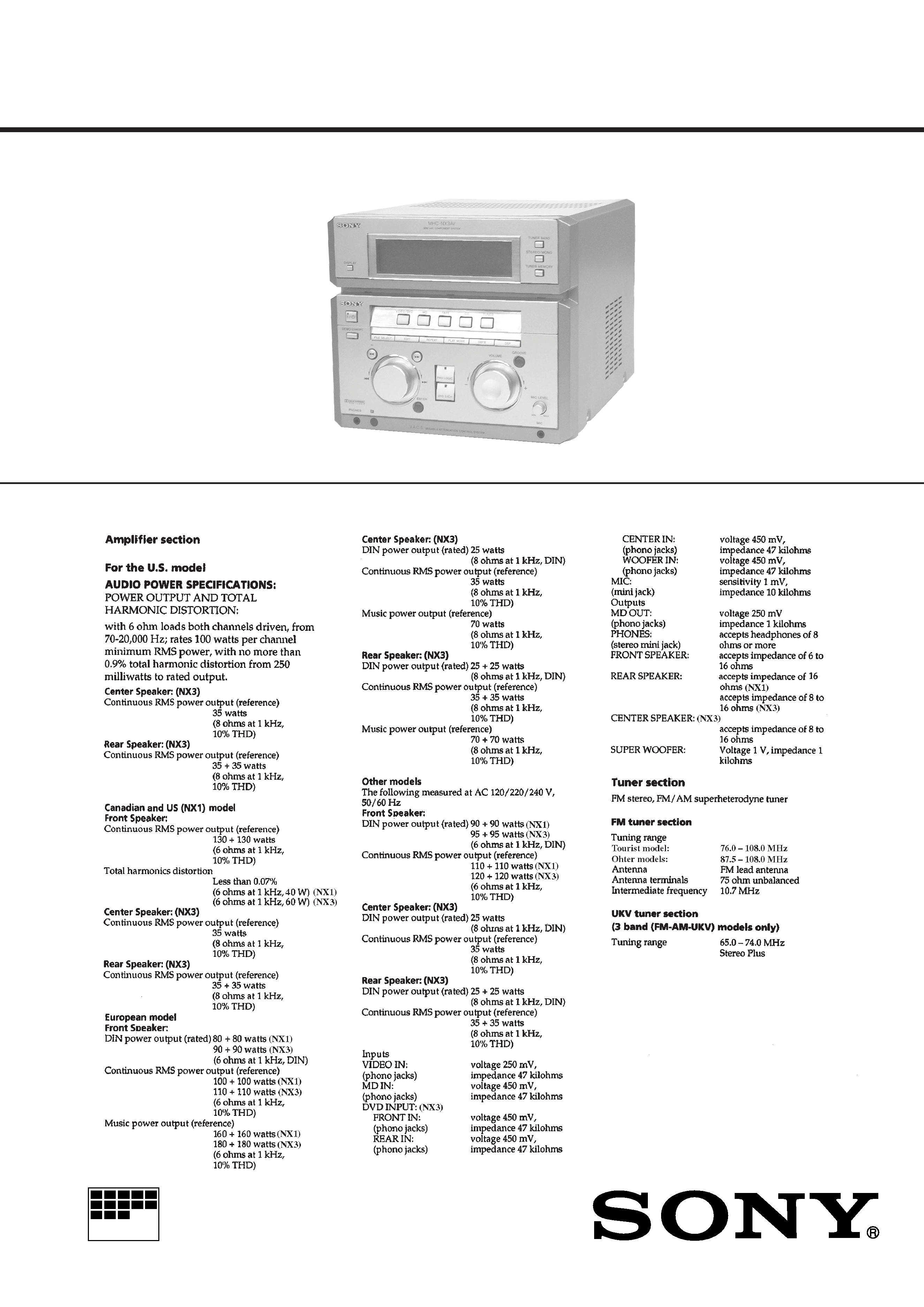
SPECIFICATIONS
STR-NX1/NX3
STR-NX1/NX3 are the
Tuner and Amplifier
Section in HMC-NX1/NX3AV.
Photo: STR-NX3 E model
Continued on next page
2
TABLE OF CONTENTS
1.
SERVICING NOTES ............................................... 3
2.
GENERAL ................................................................... 4
3.
DISASSEMBLY ......................................................... 6
4.
TEST MODE .............................................................. 8
5.
DIAGRAMS
5-1. Note for Printed Wiring Boards and
Schematic Diagrams ....................................................... 11
5-2. Schematic Diagram MAIN Board (1/3) ................... 12
5-3. Schematic Diagram MAIN Board (2/3) ................... 13
5-4. Schematic Diagram MAIN Board (3/3) ................... 14
5-5. Printed Wiring Board MAIN Board ........................ 15
5-6. Printed Wiring Board SURROUND AMP Board ... 16
5-7. Schematic Diagram SURROUND AMP Board ...... 17
5-8. Printed Wiring Board PA Board .............................. 18
5-9. Schematic Diagram PA Board ................................. 19
5-10. Printed Wiring Boards PANEL Section .................. 20
5-11. Schematic Diagram PANEL Section ....................... 21
5-12. Printed Wiring Boards
TRANSFORMER Section ........................................ 22
5-13. Schematic Diagram TRANSFORMER Section ...... 23
5-14. IC Pin Function Description ........................................... 24
6.
EXPLODED VIEWS ................................................ 26
7.
ELECTRICAL PARTS LIST ............................... 30
ATTENTION AU COMPOSANT AYANT RAPPORT
À LA SÉCURITÉ!
LES COMPOSANTS IDENTIFIÉS PAR UNE MARQUE 0
SUR LES DIAGRAMMES SCHÉMATIQUES ET LA LISTE
DES PIÈCES SONT CRITIQUES POUR LA SÉCURITÉ
DE FONCTIONNEMENT. NE REMPLACER CES COM-
POSANTS QUE PAR DES PIÈCES SONY DONT LES
NUMÉROS SONT DONNÉS DANS CE MANUEL OU
DANS LES SUPPLÉMENTS PUBLIÉS PAR SONY.
SAFETY-RELATED COMPONENT WARNING!!
COMPONENTS IDENTIFIED BY MARK 0 OR DOTTED
LINE WITH MARK 0 ON THE SCHEMATIC DIAGRAMS
AND IN THE PARTS LIST ARE CRITICAL TO SAFE
OPERATION. REPLACE THESE COMPONENTS WITH
SONY PARTS WHOSE PART NUMBERS APPEAR AS
SHOWN IN THIS MANUAL OR IN SUPPLEMENTS PUB-
LISHED BY SONY.
3
SECTION 1
SERVICING NOTES
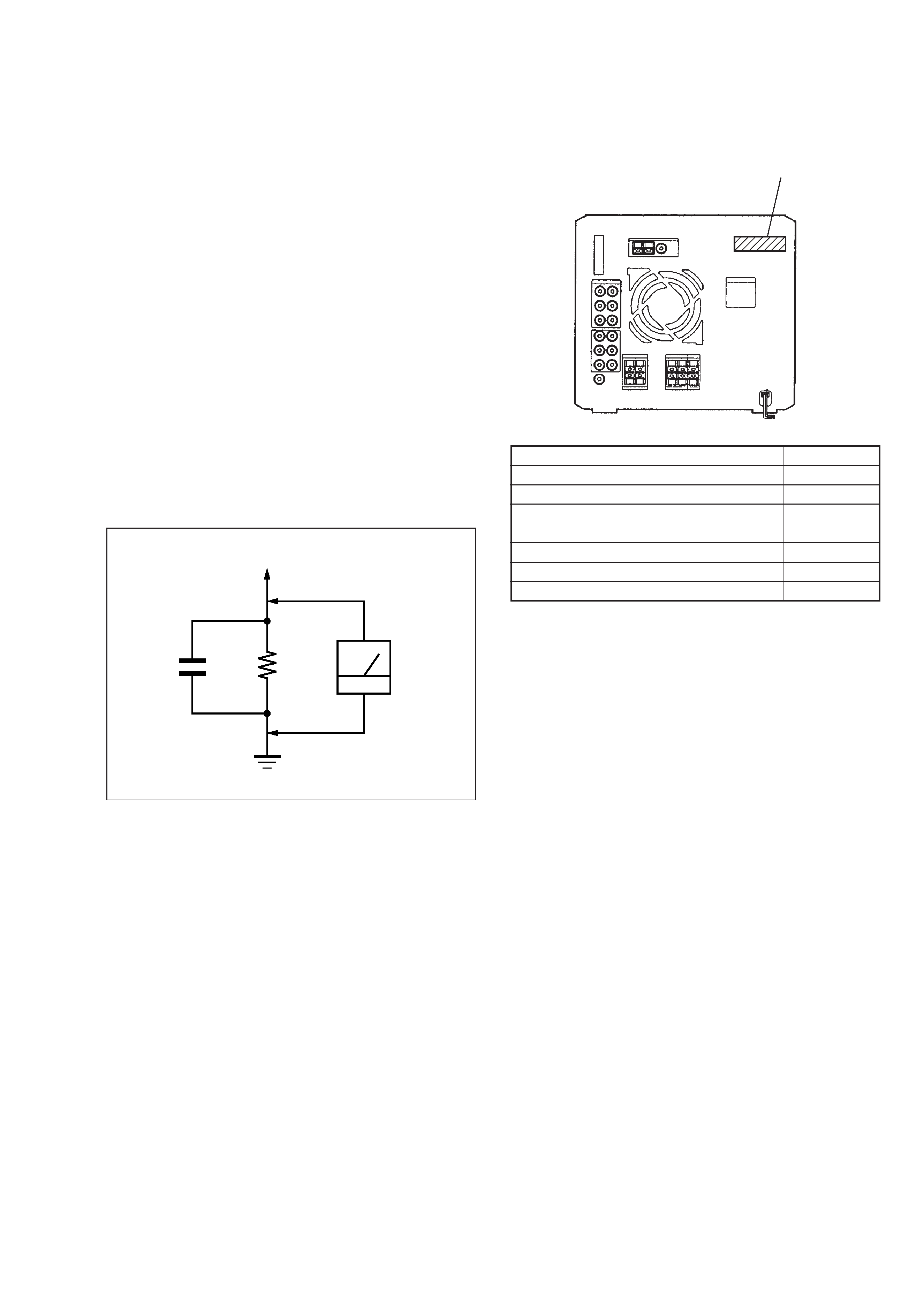
Fig. A.
Using an AC voltmeter to check AC leakage.
1.5 k
0.15
µF
AC
voltmeter
(0.75 V)
To Exposed Metal
Parts on Set
Earth Ground
SAFETY CHECK-OUT
After correcting the original service problem, perform the follow-
ing safety check before releasing the set to the customer:
Check the antenna terminals, metal trim, "metallized" knobs,
screws, and all other exposed metal parts for AC leakage.
Check leakage as described below.
LEAKAGE TEST
The AC leakage from any exposed metal part to earth ground and
from all exposed metal parts to any exposed metal part having a
return to chassis, must not exceed 0.5 mA (500 microamperes).
Leakage current can be measured by any one of three methods.
1. A commercial leakage tester, such as the Simpson 229 or RCA
WT-540A. Follow the manufacturers' instructions to use these
instruments.
2. A battery-operated AC milliammeter. The Data Precision 245
digital multimeter is suitable for this job.
3. Measuring the voltage drop across a resistor by means of a
VOM or battery-operated AC voltmeter. The "limit" indica-
tion is 0.75 V, so analog meters must have an accurate low-
voltage scale. The Simpson 250 and Sanwa SH-63Trd are ex-
amples of a passive VOM that is suitable. Nearly all battery
operated digital multimeters that have a 2 V AC range are suit-
able. (See Fig. A)
MODEL
PART No.
NX1: AEP, UK and Korean models
4-221-391-0[]
NX1: US and Canadian models
4-221-391-1[]
NX1: Malaysia, Singapore, Thai and
Tourist models
4-221-391-2[]
NX3: AEP, UK, Korean and Australian models
4-221-391-3[]
NX3: US and Canadian models
4-221-391-4[]
NX3: Malaysia and Singapore models
4-221-391-5[]
· MODEL IDENTIFICATION
Rear Panel
PART No.
4
SECTION 2
GENERAL
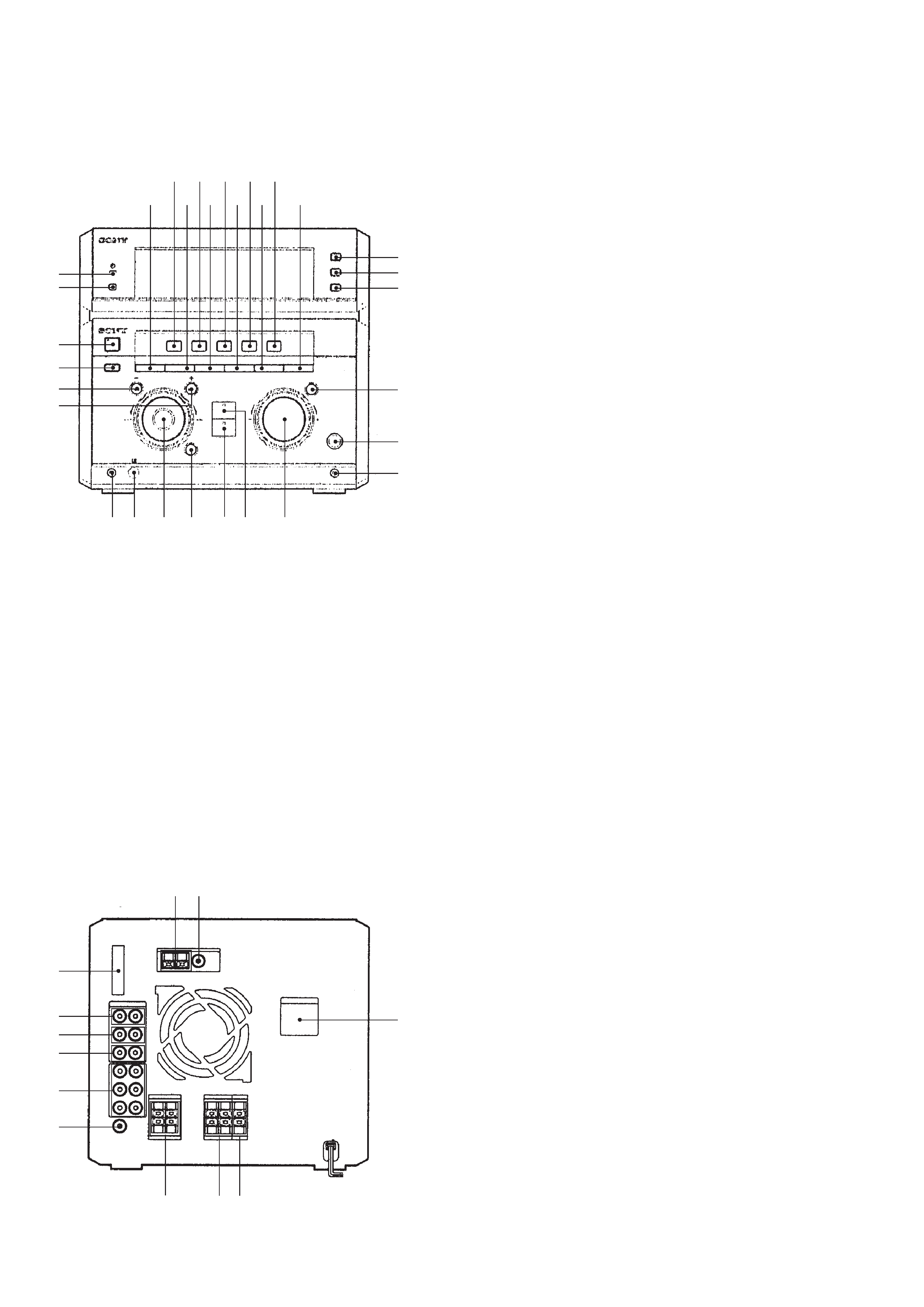
· LOCATION OF CONTROLS
Front Panel
Rear Panel
1 TIMER indicator (US, Canadian, AEP and UK models)
2 DISPLAY button
3 ?/1 button and indicator
4 POWER SAVE/DEMO (STANDBY) button
5 m button
6 + M button
7 FILE SELECT button
8 VIDEO/DVD button
9 EDIT button
q; MD button
qa REPEAT button
qs TAPE button
qd PLAY MODE button
qf CD button
qg DBFB button
qh TUNER button
qj DSP button
qk TUNER BAND button
ql STEREO/MONO button
w; TUNER MEMORY button
wa GROOVE button and indicator
ws MIC LEVEL knob
wd MIC jack
wf PHONES jack
wg Remote sensor
wh Jog dial
wj ENTER button and indicator
wk DVD 5.1CH button and indicator (STR-NX3)
wl PRO LOGIC button and indicator (STR-NX3)
e; VOLUME knob
1 AM ANTENNA terminals
2 FM ANTENNA terminal
3 SYSTEM CONTROL connector
4 VIDEO (AUDIO) IN jacks
5 MD IN jacks
6 MD OUT jacks
7 DVD 5.1CH INPUT jacks (STR-NX3)
8 SUPER WOOFER OUT jack
9 VOLTAGE SELECTOR switch
(Malaysia, Singapore and Tourist models)
q; FRONT SPEAKER terminals
qa REAR SPEAKER terminals
qs CENTER SPEAKER terminals (STR-NX3)
12
3
4
5
6
7
8
q;
qa qs
9
7
9 qa qd qg
qj
8 q; qsqfqh
1
2
3
4
5
6
qk
ql
w;
wa
ws
wd
wf wg
wh
wj
wk wl
e;
5
This section is extracted from
instruction manual.