1
SERVICE MANUAL
US Model
STR-K5900P/K9900P
Canadian Model
STR-K5900P
STR-K5900P/K9900P
FM STEREO/FM-AM RECEIVER
AUDIO POWER SPECIFICATIONS
POWER OUTPUT AND TOTAL HARMONIC
DISTORTION:
(Models of area code US only)
With 6 ohm loads, both channels driven, from
120 20,000 Hz; rated 90 watts (STR-K9900P)/
70 watts (STR-K5900P) per channel minimum
RMS power, with no more than 0.7 % total
harmonic distortion from 250 milliwatts to rated
output.
Amplifier section
Power Output 1)
Model of area code US
(6 ohms 1 kHz, THD 10 %)
STR-K9900P:
FRONT 2) : 140 W/ch
CENTER 2) : 140 W
SURR 2) : 140 W/ch
SURR BACK 2) : 140 W
STR-K5900P:
FRONT 2) : 110 W/ch
CENTER 2) : 110 W
SURR 2) : 110 W/ch
SURR BACK 2) : 110 W
SPECIFICATIONS
Model of area code Canadian
(6 ohms 1 kHz, THD 0.7 %)
STR-K5900P:
FRONT 2) : 70 W/ch
CENTER 2) : 70 W
SURR 2) : 70 W/ch
SURR BACK 2) : 70 W
(6 ohms 1 kHz, THD 10 %)
STR-K5900P:
FRONT 2) : 110 W/ch
CENTER 2) : 110 W
SURR 2) : 110 W/ch
SURR BACK 2) : 110 W
1) Measured under the following conditions:
Area code
Power requirements
US, Canadian
120 V AC, 60 Hz
2) Depending on the sound field settings and the
source, there may be no sound output.
Ver. 1.0 2005. 03
9-879-562-01
2005C04-1
© 2005. 03
Sony Corporation
Audio Group
Published by Sony Engineering Corporation
Manufactured under license from Dolby Laboratories.
"Dolby", "Pro Logic" and the double-D symbol are
trademarks of Dolby Laboratories.
"DTS", "DTS-ES", "Neo:6" and "DTS 96/24" are
trademarks of Digital Theater Systems, Inc.
Continued on next page
Photo: STR-K9900P
· STR-K5900P/K9900P are the
FM/AM receiver section in
HT-5950DP/6900DP/9900M.

2
STR-K5900P/K9900P
Inputs (Analog)
MULTI CH IN*,
Sensitivity: 800 mV
SA-CD/CD, MD/TAPE,
Impedance: 50 k ohms
DVD, VIDEO 1, 2, 3
* STR-K9900P only.
Inputs (Digital)
DVD (Coaxial)
Sensitivity:
Impedance: 75 ohms
VIDEO 2, SA-CD/CD
Sensitivity:
(Optical)
Impedance:
Outputs (Analog)
MD/TAPE (OUT),
Voltage: 800 mV
VIDEO 1 (AUDIO OUT)
Impedance: 10 k ohms
SUB WOOFER
Voltage: 2 V
Impedance: 1 k ohm
Reproduction frequency range:
28 20,000 Hz
Tone
Gain levels
±6 dB, 1 dB step
FM tuner section
Tuning range
87.5 108.0 MHz
Antenna
FM wire antenna
Antenna terminals
75 ohms, unbalanced
Intermediate frequency
10.7 MHz
AM tuner section
Tuning range
Model of area code US, Canadian
With 10-kHz tuning scale:
530 1,710 kHz 3)
With 9-kHz tuning scale:
531 1,710 kHz 3)
Antenna
Loop antenna
Intermediate frequency
450 kHz
3) You can change the AM tuning scale to 9 kHz or 10 kHz.
After tuning in any AM station, turn off the receiver. While
holding down PRESET TUNING + or TUNING +, press
?/1. All preset stations will be erased when you change
the tuning scale. To reset the scale to 10 kHz (or 9 kHz),
repeat the procedure.
Video section
Inputs/Outputs
Video:
1 Vp-p, 75 ohms
COMPONENT VIDEO:
Y: 1 Vp-p, 75 ohms
PB/CB/B-Y: 0.7 Vp-p,
75 ohms
PR/CR/R-Y: 0.7 Vp-p,
75 ohms
80 MHz HD Pass Through
General
Power requirements
Area code
Power requirements
US, Canadian
120 V AC, 60 Hz
Power consumption
Area code
Power consumption
US (STR-K9900P)
190 W
US (STR-K5900P)
140 W
Canadian
200 VA
Power consumption (during standby mode)
0.2 W
Dimensions (w/h/d) (Approx.)
430
× 157.5 × 310 mm
(16 7/8
× 6 2/8 × 12 2/8
inches) including
projecting parts and
controls
Mass (Approx.)
8.0 kg (17 lb 11 oz)
Design and specifications are subject to change
without notice.
3
STR-K5900P/K9900P
SAFETY-RELATED COMPONENT WARNING!!
COMPONENTS IDENTIFIED BY MARK 0 OR DOTTED LINE
WITH MARK 0 ON THE SCHEMATIC DIAGRAMS AND IN
THE PARTS LIST ARE CRITICAL TO SAFE OPERATION.
REPLACE THESE COMPONENTS WITH SONY PARTS WHOSE
PART NUMBERS APPEAR AS SHOWN IN THIS MANUAL OR
IN SUPPLEMENTS PUBLISHED BY SONY.
ATTENTION AU COMPOSANT AYANT RAPPORT
À LA SÉCURITÉ!!
LES COMPOSANTS IDENTIFIÉS PAR UNE MARQUE 0 SUR LES
DIAGRAMMES SCHÉMATIQUES ET LA LISTE DES PIÈCES
SONT CRITIQUES POUR LA SÉCURITÉ DE FONCTIONNEMENT.
NE REMPLACER CES COMPOSANTS QUE PAR DES PIÈCES
SONY DONT LES NUMÉROS SONT DONNÉS DANS CE MANUEL
OU DANS LES SUPPLÉMENTS PUBLIÉS PAR SONY.
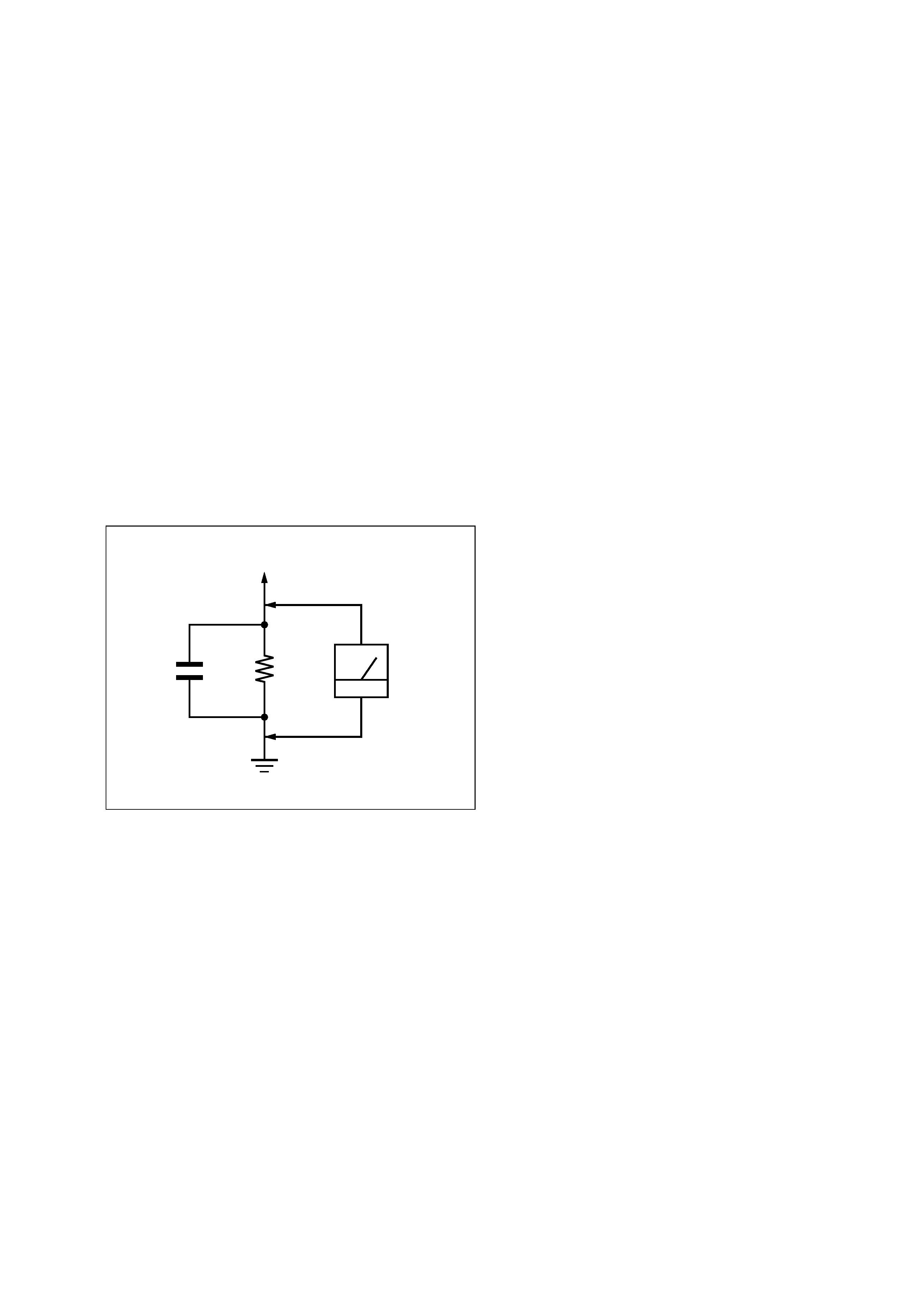
1.5 k
0.15 µF
AC
voltmeter
(0.75 V)
To Exposed Metal
Parts on Set
Earth Ground
SAFETY CHECK-OUT (US MODEL)
After correcting the original service problem, perform the follow-
ing safety check before releasing the set to the customer:
Check the antenna terminals, metal trim, "metallized" knobs, screws,
and all other exposed metal parts for AC leakage.
Check leakage as described below.
LEAKAGE TEST
The AC leakage from any exposed metal part to earth ground and
from all exposed metal parts to any exposed metal part having a
return to chassis, must not exceed 0.5 mA (500 microampers.).
Leakage current can be measured by any one of three methods.
1. A commercial leakage tester, such as the Simpson 229 or RCA
WT-540A. Follow the manufacturers' instructions to use these
instruments.
2. A battery-operated AC milliammeter. The Data Precision 245
digital multimeter is suitable for this job.
3. Measuring the voltage drop across a resistor by means of a
VOM or battery-operated AC voltmeter. The "limit" indica-
tion is 0.75 V, so analog meters must have an accurate low-
voltage scale. The Simpson 250 and Sanwa SH-63Trd are ex-
amples of a passive VOM that is suitable. Nearly all battery
operated digital multimeters that have a 2 V AC range are suit-
able. (See Fig. A)
Fig. A. Using an AC voltmeter to check AC leakage.
4
STR-K5900P/K9900P
TABLE OF CONTENTS
1. GENERAL
Main unit ................................................................................. 5
Remote button description ....................................................... 6
2. DISASSEMBLY
2-1. Case ..................................................................................... 7
2-2. Front Panel Section ............................................................. 8
2-3. Back Panel Section .............................................................. 8
2-4. Digital Board ....................................................................... 9
2-5. Standby Board ..................................................................... 9
2-6. Main Board ....................................................................... 10
3. TEST MODE ..................................................................... 11
4. DIAGRAMS
4-1. Circuit Boards Location .................................................... 12
4-2. Block Diagram Tuner/Audio Section .......................... 13
4-3. Block Diagram Digital Section ................................... 14
4-4. Block Diagram Video Section ..................................... 15
4-5. Block Diagram Key/Display Section .......................... 16
4-6. Block Diagram Power Section .................................... 17
4-7. Printed Wiring Boards Main Section .......................... 19
4-8. Schematic Diagram Main Section (1/2) ...................... 20
4-9. Schematic Diagram Main Section (2/2) ...................... 21
4-10. Printed Wiring Board Digital Section (1/2) ................ 22
4-11. Printed Wiring Board Digital Section (2/2) ................ 23
4-12. Schematic Diagram Digital Section (1/4) ................... 24
4-13. Schematic Diagram Digital Section (2/4) ................... 25
4-14. Schematic Diagram Digital Section (3/4) ................... 26
4-15. Schematic Diagram Digital Section (4/4) ................... 27
4-16. Printed Wiring Boards Speaker Section ...................... 28
4-17. Schematic Diagram Speaker Section .......................... 29
4-18. Printed Wiring Boards Video Section ......................... 30
4-19. Schematic Diagram Video Section .............................. 31
4-20. Printed Wiring Boards Panel Section .......................... 32
4-21. Schematic Diagram Panel Section .............................. 33
4-22. Printed Wiring Board Power Section .......................... 34
4-23. Schematic Diagram Power Section ............................. 35
5. EXPLODED VIEWS
5-1. Case Section ...................................................................... 42
5-2. Front Panel Section ........................................................... 43
5-3. Back Panel Section ............................................................ 44
5-4. Chassis Section ................................................................. 45
6. ELECTRICAL PARTS LIST ........................................ 46
MODEL IDENTIFICATION
-- BACK PANEL --
Part No.
MODEL
PART No.
STR-K5900P: US
2-546-121-0s
STR-K9900P: US
2-546-121-1s
STR-K5900P: CND
2-546-121-7s
·Abbreviation
CND : Canadian model
5
STR-K5900P/K9900P
SECTION 1
GENERAL
This section is extracted
from instruction manual.
59US
Ad
dition
al
I
n
fo
rm
atio
n
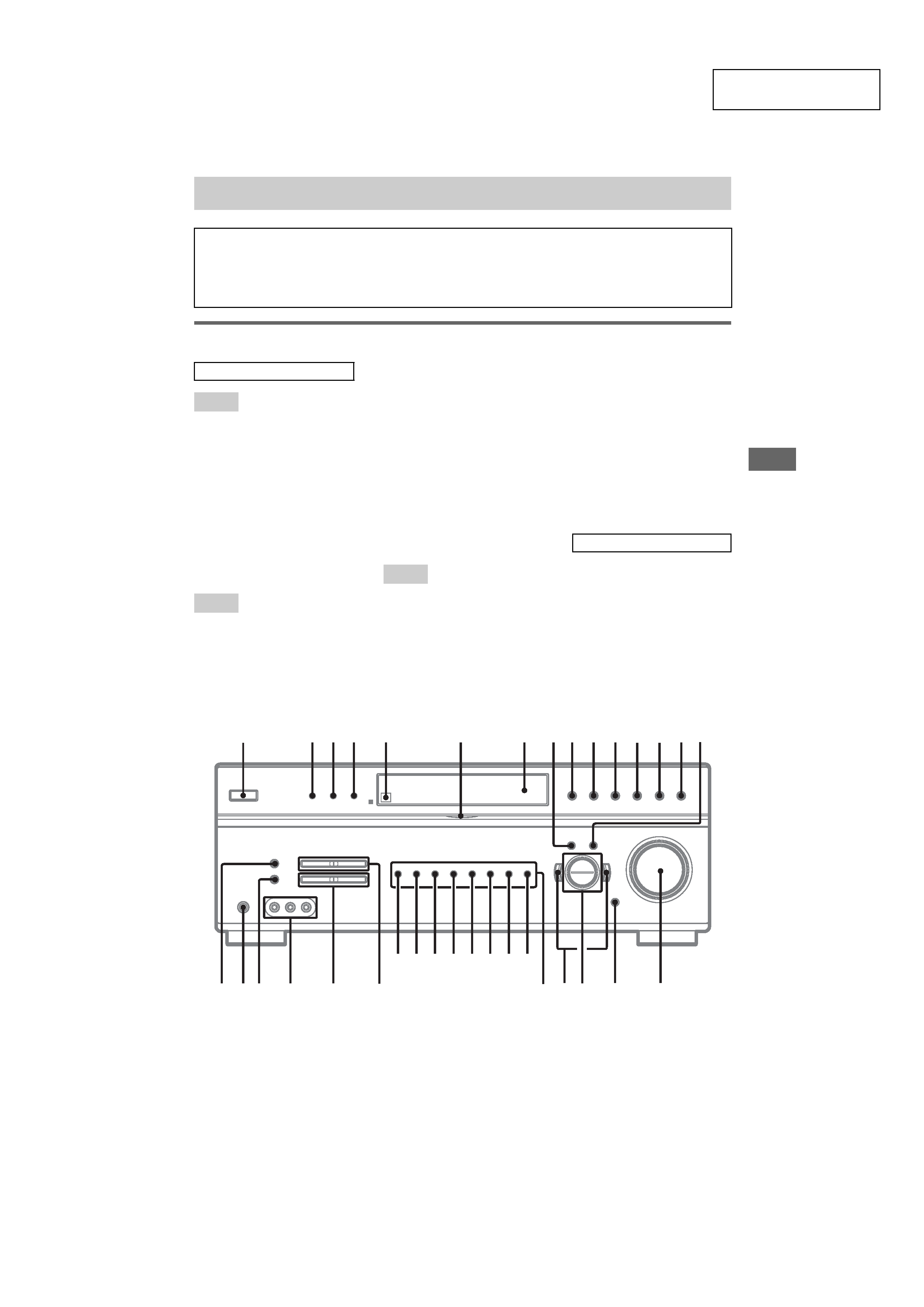
Main unit
A.F.D. (button/indicator) qa (30,
32, 53)
AM wa (23, 24, 25, 40)
DIMMER 4 (26)
DISPLAY 3 (26, 54)
Display 7 (27)
DVD wg (23)
ENTER qg (18, 40)
FM ws (23, 24, 25, 40)
FM MODE es (24)
Input buttons w; (23, 35, 39, 40,
54)
INPUT MODE qj (35)
IR (receptor) 5 (43, 54)
MAIN MENU 8 (19, 36, 37, 40)
MASTER VOLUME /+ qh (18,
22, 23, 53)
MD/TAPE wf (23)
MEMORY ef (25)
MOVIE (button/indicator) qs
(31, 32, 53)
MULTI CHANNEL DECODING
(indicator) 6 (24)
MULTI CH IN* 9 (24)
MUSIC (button/indicator) qd (32,
53)
PHONES (jack) ed (23, 53)
PRESET TUNING /+ wl (25,
56)
SA-CD/CD wd (23)
SLEEP** 9 (40)
SPEAKERS (OFF/A/B/A+B)*
2 (16, 41, 53)
SPEAKERS (ON/OFF)** 2 (16,
41, 53)
SURR BACK DECODING qf
(33)
TUNING /+ e; (24, 56)
VIDEO 1 wk (23)
VIDEO 2 wj (23)
VIDEO 3 wh (23)
VIDEO 3 IN/PORTABLE AV IN
(jacks) ea (13)
2CH (button/indicator) q; (29,
32, 37)
?/1 (power) 1 (18, 19, 37, 56)
</> ql (19, 36, 37, 40)
+/ qk (19, 36, 38, 40)
*HT-9900M and HT-6900DP
only.
** HT-5950DP only.
List of button locations and reference pages
How to use this page
Use this page to find the location of buttons that are
mentioned in the text.
Illustration number
r
DISPLAY 3 (26, 54)
RR
Name of button/part
Reference page
ALPHABETICAL ORDER
A - H
I - O
P - Z
NUMBERS AND SYMBOLS
2
8
6
5
34
7
1
wa
ws
wd
wf
wg
wh
wj
wk
qj
ql
qh
9q; qa qs
qf
qd
qg
w;
wl
e;
ed es
ef
ea
qk