SERVICE MANUAL
Sony Corporation
Audio Group
Published by Sony Engineering Corporation
US Model
FM STEREO FM-AM RECEIVER
9-879-446-01
2005C1678-1
© 2005.03
Ver. 1.0 2005.03
SPECIFICATIONS
STR-K675P
· STR-K675P is the tuner and the amplifier
section in HT-DDW675.
Manufactured under license from Dolby Laboratories.
"Dolby", "Pro Logic" and the double-D symbol are trademarks
of Dolby Laboratories.
"DTS" and "DTS Digital Surround" are registered trademarks of
Digital Theater Systems, Inc.
AUDIO POWER SPECIFICATIONS
POWER OUTPUT AND TOTAL HARMONIC
DISTORTION:
(Models of area code US only)
With 6 ohm loads, both channels driven, from
120 20,000 Hz; rated 70 watts per channel
minimum RMS power, with no more than 0.7%
total harmonic distortion from 250 milliwatts to
rated output.
Amplifier section
Power Output1)
(6 ohms 1 kHz, THD 10%)
FRONT2):
110 W/ch
CENTER2):
110 W
SURR2):
110 W/ch
FM tuner section
Tuning range
87.5 - 108.0 MHz
Antenna
FM wire antenna
Antenna terminals
75 ohms, unbalanced
Intermediate frequency
10.7 MHz
AM tuner section
Tuning range
With 10-kHz tuning scale: 530 - 1,710 kHz3)
With 9-kHz tuning scale: 531 - 1,710 kHz3)
Antenna
Loop antenna
Intermediate frequency
450 kHz
3) You can change the AM tuning scale to 9 kHz or
10 kHz. After tuning in any AM station, turn off the
receiver. While holding down PRESET TUNING +
or TUNING +, press ?/1. All preset stations will be
erased when you change the tuning scale. To reset
the scale to 10 kHz (or 9 kHz), repeat the procedure.
1) Measured under the following conditions:
2) Depending on the sound field settings and the
source, there may be no sound output.
Inputs (Analog)
Inputs (Digital)
Output (Analog)
Reproduction frequency range:
28 20,000 Hz
Tone
120 V AC, 60 Hz
SA-CD/CD, DVD
VIDEO 1, 2
Sensitivity: 800 mV
Impedance: 50 k ohms
DVD (Coaxial)
Sensitivity:
Impedance: 75 ohms
SA-CD/CD (Optical)
Sensitivity:
Impedance:
SUB WOOFER
Voltage: 2 V
Impedance: 1 k ohm
Gain levels
±6 dB, 1 dB step
General
Power requirements
120 V AC, 60 Hz
Power consumption
Power consumption (during standby mode)
0.2 W
Dimensions (w/h/d) (Approx.)
430
× 145 × 301.5 mm
(17
× 5 6/8 × 11 7/8 inches)
including projecting parts
and controls
Mass (Approx.)
6.5 kg (14 lb 6 oz)
170 W
Design and specifications are subject to change
without notice
2
STR-K675P
TABLE OF CONTENTS
1.
GENERAL ................................................................... 3
2.
TEST MODE ............................................................... 7
3.
DIAGRAMS
3-1.
Block Diagram -- MAIN Section -- .............................. 10
3-2.
Block Diagram -- DISPLAY/POWER Section -- ........ 11
3-3.
Printed Wiring Board
-- DIGITAL Board (Side A) -- ...................................... 12
3-4.
Printed Wiring Board
-- DIGITAL Board (Side B) -- ...................................... 13
3-5.
Schematic Diagram -- DIGITAL Board (1/4) -- .......... 14
3-6.
Schematic Diagram -- DIGITAL Board (2/4) -- .......... 15
3-7.
Schematic Diagram -- DIGITAL Board (3/4) -- .......... 16
3-8.
Schematic Diagram -- DIGITAL Board (4/4) -- .......... 17
3-9.
Printed Wiring Board -- MAIN Section -- ................... 18
3-10. Schematic Diagram -- MAIN Section (1/3) -- ............. 19
3-11. Schematic Diagram -- MAIN Section (2/3) -- ............. 20
3-12. Schematic Diagram -- MAIN Section (3/3) -- ............. 21
3-13. Printed Wiring Board -- STANDBY Section -- ........... 22
3-14. Printed Wiring Board -- DISPLAY Section -- ............. 23
3-15. Schematic Diagram -- DISPLAY Section -- ................ 24
3-16. Printed Wiring Board -- VIDEO Board -- .................... 25
3-17. Schematic Diagram -- VIDEO Board -- ...................... 26
4.
EXPLODED VIEWS
4-1.
Front Panel Section ......................................................... 34
4-2.
Chassis Section ................................................................ 35
5.
ELECTRICAL PARTS LIST .................................. 36
SAFETY CHECK-OUT
After correcting the original service problem, perform the following
safety check before releasing the set to the customer:
Check the antenna terminals, metal trim, "metallized" knobs, screws,
and all other exposed metal parts for AC leakage.
Check leakage as described below.
LEAKAGE TEST
The AC leakage from any exposed metal part to earth ground and
from all exposed metal parts to any exposed metal part having a
return to chassis, must not exceed 0.5 mA (500 microamperes.).
Leakage current can be measured by any one of three methods.
1. A commercial leakage tester, such as the Simpson 229 or RCA
WT-540A. Follow the manufacturers' instructions to use these
instruments.
2. A battery-operated AC milliammeter. The Data Precision 245
digital multimeter is suitable for this job.
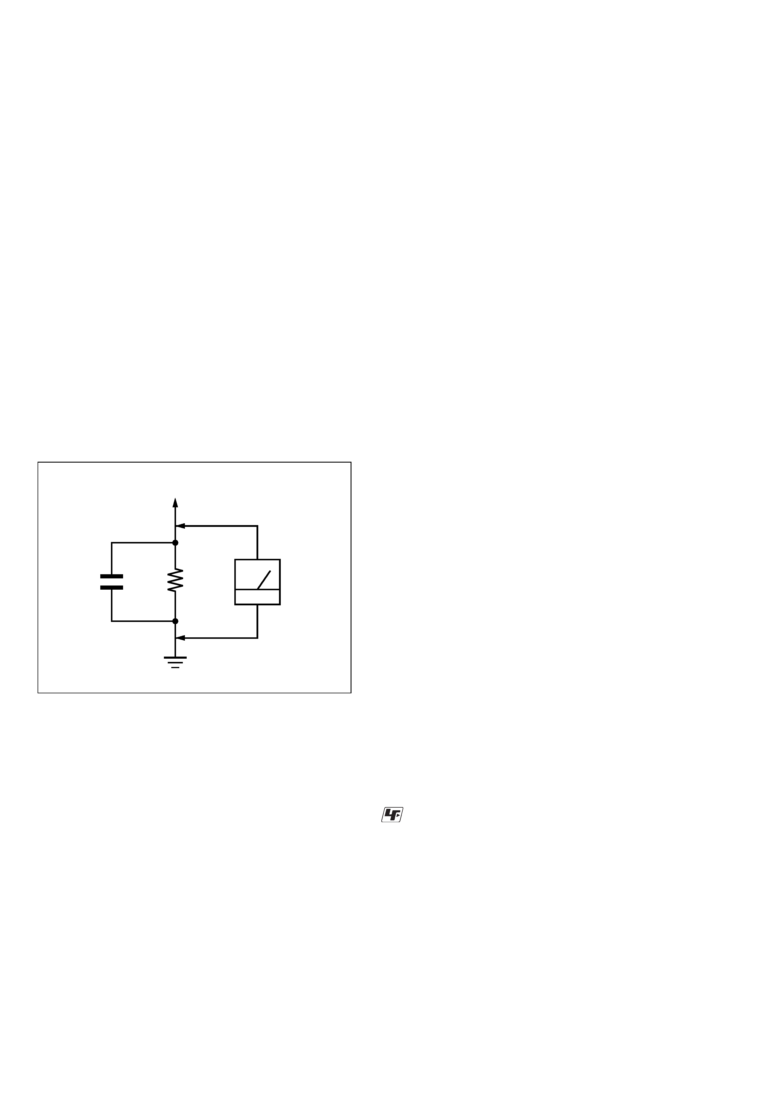
3. Measuring the voltage drop across a resistor by means of a
VOM or battery-operated AC voltmeter. The "limit" indication
is 0.75 V, so analog meters must have an accurate low-voltage
scale. The Simpson 250 and Sanwa SH-63Trd are examples
of a passive VOM that is suitable. Nearly all battery operated
digital multimeters that have a 2 V AC range are suitable. (See
Fig. A)
Fig. A.
Using an AC voltmeter to check AC leakage.
1.5 k
0.15
µF
AC
voltmeter
(0.75 V)
To Exposed Metal
Parts on Set
Earth Ground
Notes on chip component replacement
· Never reuse a disconnected chip component.
· Notice that the minus side of a tantalum capacitor may be
damaged by heat.
UNLEADED SOLDER
Boards requiring use of unleaded solder are printed with the lead-
free mark (LF) indicating the solder contains no lead.
(Caution: Some printed circuit boards may not come printed with
the lead free mark due to their particular size)
: LEAD FREE MARK
Unleaded solder has the following characteristics.
· Unleaded solder melts at a temperature about 40 °C higher
than ordinary solder.
Ordinary soldering irons can be used but the iron tip has to be
applied to the solder joint for a slightly longer time.
Soldering irons using a temperature regulator should be set to
about 350
°C.
Caution: The printed pattern (copper foil) may peel away if
the heated tip is applied for too long, so be careful!
· Strong viscosity
Unleaded solder is more viscou-s (sticky, less prone to flow)
than ordinary solder so use caution not to let solder bridges
occur such as on IC pins, etc.
· Usable with ordinary solder
It is best to use only unleaded solder but unleaded solder may
also be added to ordinary solder.
SAFETY-RELATED COMPONENT WARNING!!
COMPONENTS IDENTIFIED BY MARK 0 OR DOTTED LINE
WITH MARK 0 ON THE SCHEMATIC DIAGRAMS AND IN
THE PARTS LIST ARE CRITICAL TO SAFE OPERATION.
REPLACE THESE COMPONENTS WITH SONY PARTS WHOSE
PART NUMBERS APPEAR AS SHOWN IN THIS MANUAL OR
IN SUPPLEMENTS PUBLISHED BY SONY.
3
STR-K675P
SECTION 1
GENERAL
This section is extracted
from instruction manual.
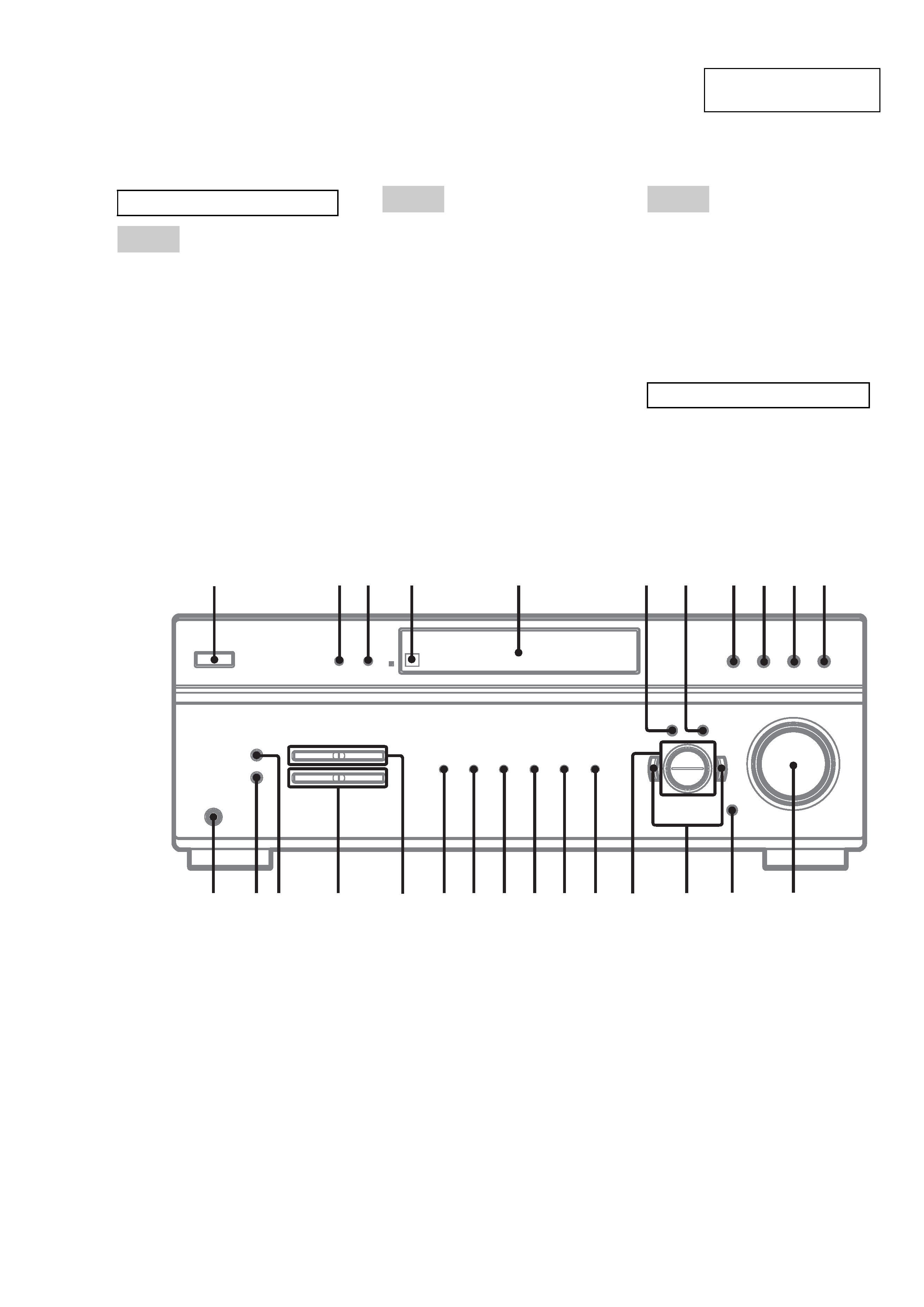
Main unit
$)' 9
$0 qh
',00(5 3
',63/$< 2
'LVSOD\ 5
'9' ql
(17(5 7
)0 qj
)0 02'( wg
,1387 02'( qd
,5 UHFHSWRU
4
0$,1 0(18 6
0$67(5 92/80( ± qs
0(025< wf
029,( 0
086,& qa
3+21(6 MDFN
wh
35(6(7 781,1* ± ws
6$&'&' qk
781,1*± wd
9,'(2 wa
9,'(2 w;
&+ 8
?/1
SRZHU
1
! qf
± qg
$/3+$%(7,&$/25'(5
$ +
,2
3 =
180%(56 $1'6<0%2/6
6
4
23
1
qh
qj
qk
ql
w;
wa
qd
qf
qs
5
7
89
qa
q;
qg
ws
wd
wh
wgwf
4
STR-K675P
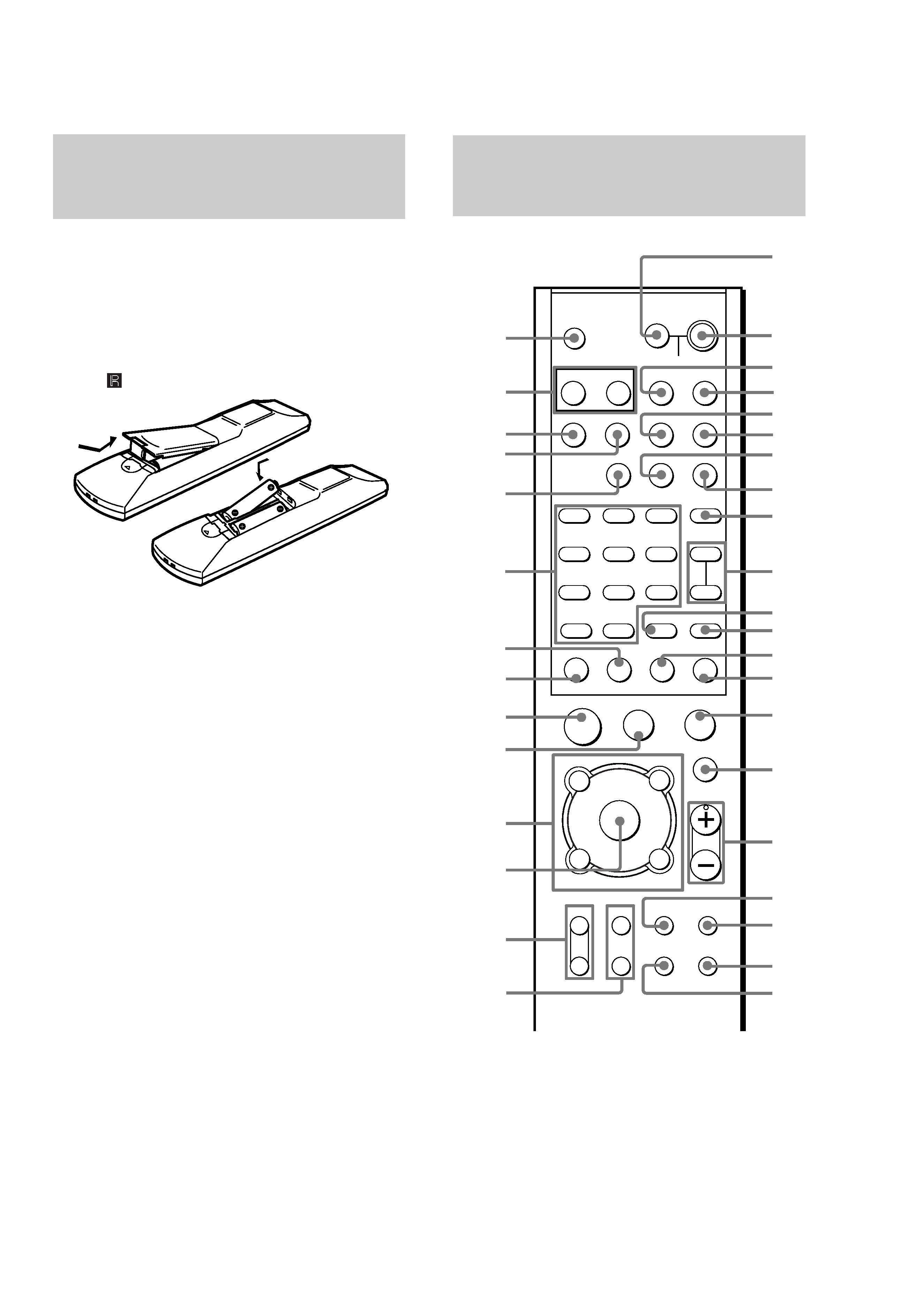
Inserting batteries into the
remote
,QVHUW 5 VL]H$$
EDWWHULHVZLWKWKHDQG±
SURSHUO\ RULHQWHGLQWKHEDWWHU\FRPSDUWPHQW
:KHQXVLQJWKHUHPRWH SRLQWLWDWWKHUHPRWH
VHQVRU
RQWKHUHFHLYHU
Tip
8QGHU QRUPDO FRQGLWLRQVWKH EDWWHULHV VKRXOG ODVW IRU
DERXWPRQWKV :KHQWKHUHPRWH QR ORQJHU RSHUDWHV
WKH UHFHLYHUUHSODFH DOO EDWWHULHV ZLWKQHZ RQHV
Notes
'R QRW OHDYH WKH UHPRWH LQ DQ H[WUHPHO\ KRW RU KXPLG
SODFH
'R QRW XVHD QHZEDWWHU\ ZLWK DQROGRQH
'R QRW H[SRVH WKH UHPRWH VHQVRU WR GLUHFW VXQOLJKW RU
OLJKWLQJDSSDUDWXVHV 'RLQJ VRPD\ FDXVHD
PDOIXQFWLRQ
,I \RX GRQ¶W XVH WKH UHPRWH IRU DQ H[WHQGHG SHULRG RI
WLPH UHPRYHWKH EDWWHULHV WR DYRLGSRVVLEOH GDPDJH
IURPEDWWHU\OHDNDJHDQGFRUURVLRQ
Before you use your
remote
v
V
b
B
v
V
b
B
7KH H 0$67(5 92/ 79 &+ DQG
79 92/ EXWWRQVKDYHD WDFWLOHGRW 8VH WKH WDFWLOH
GRWDV D UHIHUHQFH ZKHQ RSHUDWLQJ WKH UHFHLYHU DQG
RWKHUDXGLRYLGHRFRPSRQHQWV
Remote button
description
T
m
M
Xx
.
>
0/10
SYSTEM STANDBY
SELECT
DVD
FM
AM
ANT
AUDIO
ENTER
SCAN/SLOW
CLEAR
SHUTTLE
SHIFT
TOP MENU
MENU
DISPLAY
ENTER
RETURN
TV VOL
TV /
VIDEO
MAIN
MENU
WIDE
SET UP
TV CH
MUTING
MASTER
VOL
D. TUNING
MOVIE/MUSIC
T. TONE
2CH
A.F.D.
VIDEO 1
VIDEO 2
SA-CD/00
AV ?/1
TV ?/1
?/1
H
>10/11
7
89
12
45
6
12
3
+
++
CH/PRESET/
TRACKING
O
v
V
b
B
v
V
b
B
1
2
3
4
5
7
6
8
9
0
qa
qs
qd
qf
qg
qh
qj
qk
ql
w;
wa
ef
ed
es
ea
e;
wl
wk
wj
wh
wg
wf
wd
ws
*
**
*
*
*

5
STR-K675P
7KHWDEOHVEHORZVKRZ WKHVHWWLQJV RIHDFK
EXWWRQ
5HPRWH
%XWWRQ
2SHUDWLRQV
)XQFWLRQ
$)' 6 5HFHLYHU
6HOHFWVWKHGHFRGLQJ
PRGH IRU DXGLR VRXQG
$0 ea
5HFHLYHU
7R VHOHFW WKH $0 EDQG
$17 e;
'9' 3/$<(5
9,'(2
&$66(77(
5(&25'(5
9,'(2 PRGH
6HOHFWV RXWSXW VLJQDO
IURP WKHDQWHQQD
WHUPLQDO79 VLJQDORU
9&5 SURJUDP
$8',2
9
'9' 3/$<(5
9,'(2
&$66(77(
5(&25'(5
&KDQJHV WKH VRXQG WR
0XOWLSOH[ RU%LOLQJXDO
$9 ?/1
1
9&5
&' 3/$<(5
'9'
3/$<(5
7XUQV WKH DXGLRDQG
YLGHRFRPSRQHQWV RQRU
RII
&+
5HFHLYHU
6HOHFWV SUHVHW VWDWLRQV
35(6(7
75$&.,1*
± q;
'9' 3/$<(5
9,'(2
&$66(77(
5(&25'(5
9,'(2
PRGH
6HOHFWV SUHVHW FKDQQHO
'9' 3/$<(5
9,'(2
&$66(77(
5(&25'(5
9,'(2
PRGH
$GMXVW WKHWUDFNLQJ
ZKHQ GLVWRUWLRQ RFFXUV
&/($5
qs
'9' 3/$<(5
&' 3/$<(5
9,'(2
&$66(77(
5(&25'(5
'9' PRGH
&OHDUV D PLVWDNH ZKHQ
\RX SUHVVWKH LQFRUUHFW
QXPHULFEXWWRQV RU
UHWXUQVWR FRQWLQXRXV
SOD\EDFNHWF
',63/$<
wf
9,'(2
&$66(77(
5(&25'(5
'9' 3/$<(5
6HOHFWV LQIRUPDWLRQ
GLVSOD\HG RQ WKH 79
VFUHHQ
'781,1*
qd
5HFHLYHU
(QWHUVGLUHFWWXQLQJ
PRGH
'9' ed
5HFHLYHU
7RZDWFK '9' SOD\HU
9LGHRFDVVHWWH UHFRUGHU
'9' PRGH
5HPRWH
%XWWRQ
2SHUDWLRQV
)XQFWLRQ
(17(5 qa 799,'(2
&$66(77(
5(&25'(5
&' 3/$<(5
(QWHUV WKH VHOHFWLRQ
(17(5 wf 5HFHLYHU
9,'(2
&$66(77(
5(&25'(5
'9'3/$<(5
(QWHUV WKH VHOHFWLRQ
)0 es
5HFHLYHU
7R VHOHFWWKH)0
EDQG
0$,1
0(18 ql
5HFHLYHU
6HOHFWV WKHPHQX RI
WKHUHFHLYHU
0(18 wf
9&5
'9'3/$<(5
'LVSOD\V PHQX
0$67(5
92/ ±
qj
5HFHLYHU79 $GMXVWV WKH PDVWHU
YROXPH RI WKH
UHFHLYHU
029,(
086,& 7
5HFHLYHU
6HOHFWV WKH
SUHSURJUDPPHG
VRXQG ILHOGV
087,1* qh 5HFHLYHU
0XWHV WKH VRXQG IURP
WKHUHFHLYHU
5(7851
O wf
'9'3/$<(5
9,'(2
&$66(77(
5(&25'(5
'9' PRGH
5HWXUQV WR WKH
SUHYLRXV PHQX RU
H[LWV WKH PHQX
6&$1
6/2: y
qd
'9'3/$<(5
9,'(2
&$66(77(
5(&25'(5
3OD\EDFN LQVORZ
PRWLRQ
6(783 w; '9' 3/$<(5
9,'(2
&$66(77(
5(&25'(5
6HOHFWV WKH6(7 83
0(18
6+,)7 wj
5HFHLYHU
6HOHFWV DPHPRU\
SDJH IRU SUHVHWWLQJ
UDGLRVWDWLRQV RU
WXQLQJ WRSUHVHW
VWDWLRQV
6+877/(
wk wl
'9' 3/$<(5
9,'(2
&$66(77(
5(&25'(5
&KDQJHV WKH SOD\EDFN
VSHHG