STR-K402
US Model
SERVICE MANUAL
FM STEREO FM-AM RECEIVER
-- Continued on next page --
SPECIFICATIONS
Ver 1.0 2001. 04
Manufactured under license from Dolby Laboratories Licensing
Corporation.
"DOLBY" the double-D symbol ; "AC-3" and "Pro Logic" are
trademarks of Dolby Laboratories Licensing Corporation.
Outputs
MD/TAPE (OUT):
VIDEO (AUDIO OUT):
Voltages: 250 mV,
Impedance:
10 kilohms
SUB WOOFER:
Voltage: 2 V
Impedance :
1 kilohms
PHONES:
Accepts low and
high-impedance
headphones
TONE
±6 dB at 100 Hz
and 10 kHz
Sampling frequency
48 kHz (OPTICAL IN)
96 kHz (COAXIAL IN)
FM tuner section
Tuning range
87.5 - 108.0 MHz
Antenna terminals
75 ohms, unbalanced
Intermediate
frequency
10.7 MHz
Sensitivity
Mono: 18.3 dBf,
2.2
µV/75 ohms
Stereo: 38.3 dBf,
22.5
µV/75 ohms
Usable sensitivity
11.2 dBf, 1
µV/75 ohms
S/N
Mono: 76 dB
Stereo: 70 dB
Harmonic distortion at 1 kHz
Mono: 0.3%
Stereo: 0.5%
Separation
45 dB at 1 kHz
Frequency response
30 Hz - 15 kHz
+0.5/-2 dB
Selectivity
60 dB at 400 kHz
AUDIO POWER
SPECIFICATIONS
POWER OUTPUT AND
TOTAL HARMONIC
DISTORTION:
With 8 ohm loads, both
channels driven, from 40 -
20,000 Hz; rated 80 watts
per channel minimum RMS
power, with no more than
0.09% total harmonic
distortion from 250
milliwatts to rated output
Amplifier section
POWER OUTPUT
Rated Power Output at Stereo mode
(8 ohms 40 Hz - 20 kHz, THD 0.09%)
80 W + 80 W
Reference Power Output
(8 ohms 1 kHz, THD 0.7%)
Front1): 80 W/ch
Center1): 80 W
Surround1): 80 W/ch
1) Depending on the sound field settings and
the sources, there may be no sound output.
Frequency response
MULTI CH IN, CD,
MD/TAPE, DVD/LD,
TV/SAT, VIDEO:
20 Hz 20 kHz
0/ 0.5 dB (sound field,
and tone bypassed)
Inputs (Analog)
MULTI CH IN, CD,
MD/TAPE, DVD/LD,
TV/SAT, VIDEO:
Sensitivity: 250 mV
Impedance:
50 kilohms
S/N2): 85 dB
(A, 250 mV3))
2) INPUT SHORT
3) Weighted network, input level
Inputs (Digital)
DVD/LD (coaxial):
Sensitivity:
Impedance: 75 ohms
S/N: 100 dB
(A, 20 kHz LPF)
TV/SAT (Optical):
Sensitivity:
Impedance:
S/N: 100 dB
(A, 20 kHz LPF)
Sony Corporation
Home Audio Company
Shinagawa Tec Service Manual Production Group
9-873-895-11
2001D1600-1
© 2001.4
2
STR-K402
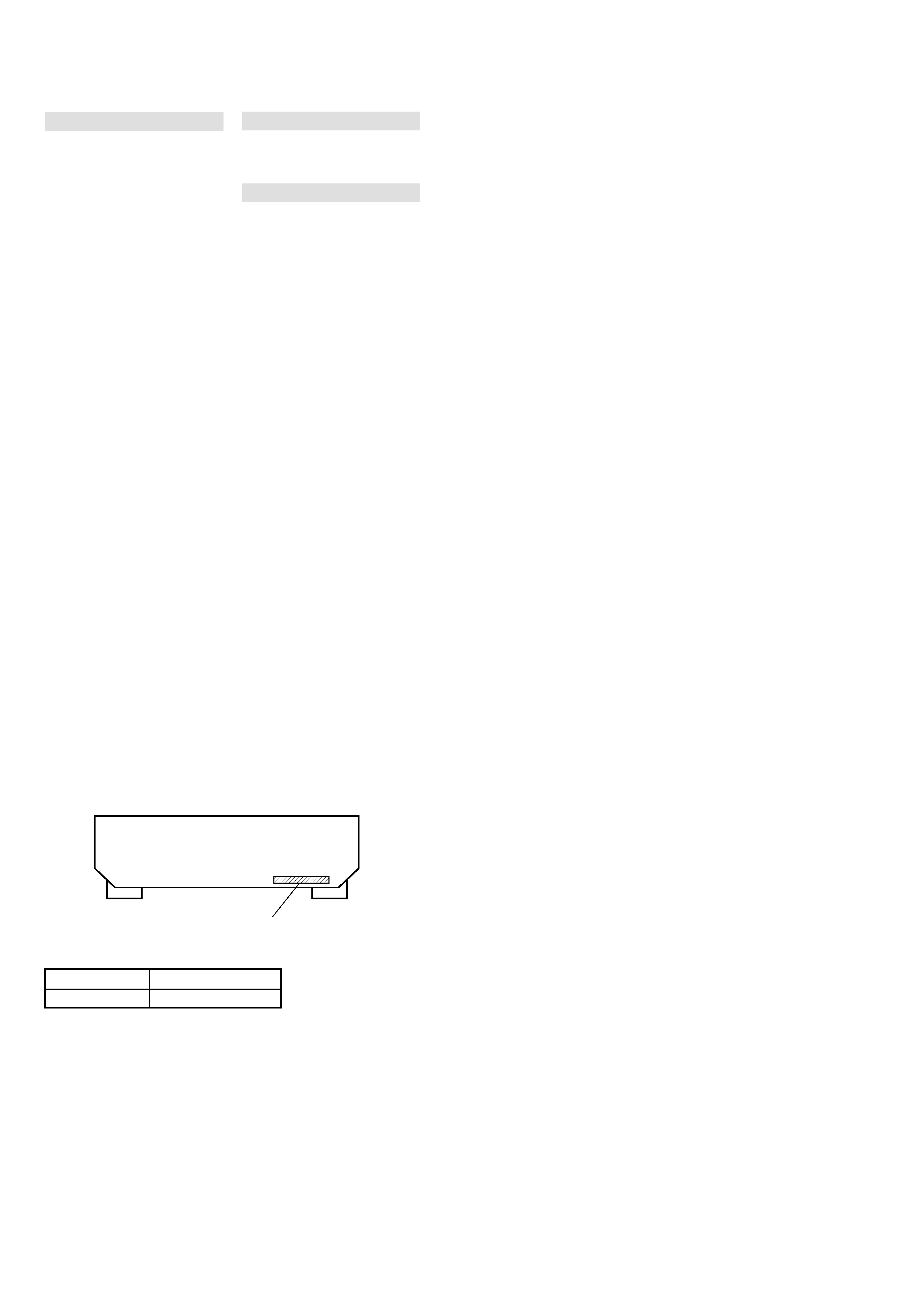
MODEL IDENTIFICATION
-- BACK PANEL --
AM tuner section
Tuning range
With 10-kHz tuning
scale:
530 - 1710 kHz4)
With 9-kHz tuning
scale:
531 - 1710 kHz4)
Antenna
Loop antenna
Intermediate
450 kHz
frequency
Usable sensitivity
50 dB/m (at 1,000 kHz
or 999 kHz)
S/N
54 dB (at 50mV/m)
Harmonic distortion
0.5% (50mV/m, 400
kHz)
Selectivity:
At 9 kHz: 35 dB
At 10 kHz: 40 dB
4) You can change the AM tuning scale to 9
kHz
10 kHz. After tuning in any AM
station, turn off the receiver. Hold down the
TUNING + button and press the
button. All preset stations will be erased
when you change the tuning scale. To reset
the scale to 10 kHz (or 9 kHz), repeat the
procedure.
Video section
Inputs
Video: 1 Vp-p 75 ohms
Outputs
Video: 1 Vp-p 75 ohms
General
System
Tuner section:
PLL quartz-locked
digital synthesizer
system
Preamplifier section:
Low-noise NF type
equalizer
Power amplifier
section:
Pure-complementary
SEPP
Power requirements
120 V AC, 60 Hz
Power consumption
185 W
In Standby
Condition:
1 W
Dimensions
430
× 145 × 298 mm
(17
7 7/8
19 5/8 in.)
including projecting
parts and controls
Mass (Approx.)
7.2 kg (15 lb 14 oz)
Supplied accessories
Design and specifications are subject
to change without notice.
· FM wire antenna (1)
· AM loop antenna (1)
· R6 (size-AA) batteries (2)
· Remote Commander (remote) (1)
××
Parts No.
MODEL
PARTS No.
US
4-235-014-0s
3
STR-K402
SAFETY-RELATED COMPONENT WARNING!!
COMPONENTS IDENTIFIED BY MARK 0 OR DOTTED LINE WITH
MARK 0 ON THE SCHEMATIC DIAGRAMS AND IN THE PARTS
LIST ARE CRITICAL TO SAFE OPERATION. REPLACE THESE
COMPONENTS WITH SONY PARTS WHOSE PART NUMBERS
APPEAR AS SHOWN IN THIS MANUAL OR IN SUPPLEMENTS
PUBLISHED BY SONY.
After correcting the original service problem, perform the
following safety checks before releasing the set to the customer:
Check the antenna terminals, metal trim, "metallized" knobs, screws,
and all other exposed metal parts for AC leakage. Check leakage as
described below.
LEAKAGE
The AC leakage from any exposed metal part to earth ground and
from all exposed metal parts to any exposed metal part having a
return to chassis, must not exceed 0.5 mA (500 microamperes).
Leakage current can be measured by any one of three methods.
1.
A commercial leakage tester, such as the Simpson 229 or RCA
WT-540A. Follow the manufacturers' instructions to use these
instruments.
2.
A battery-operated AC milliammeter. The Data Precision 245
digital multimeter is suitable for this job.
3.
Measuring the voltage drop across a resistor by means of a
VOM or battery-operated AC voltmeter. The "limit" indication
is 0.75 V, so analog meters must have an accurate low-voltage
scale. The Simpson 250 and Sanwa SH-63Trd are examples of
a passive VOM that is suitable. Nearly all battery operated
digital multimeters that have a 2V AC range are suitable. (See
Fig. A)
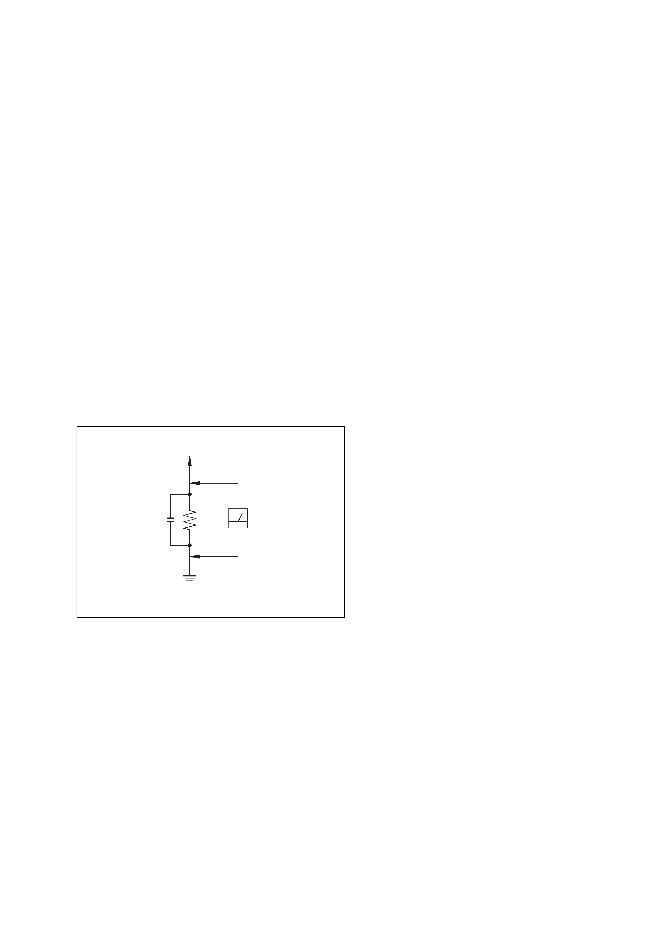
SAFETY CHECK-OUT
To Exposed Metal
Parts on Set
0.15
µF
1.5 k
AC
Voltmeter
(0.75 V)
Earth Ground
Fig. A. Using an AC voltmeter to check AC leakage.
TABLE OF CONTENTS
1. GENERAL ·········································································· 4
2. TEST MODE ······································································ 6
3. DIAGRAMS
3-1.
Circuit Boards Location ··············································· 8
3-2.
Block Diagram Main Section ····································· 9
3-3.
Block Diagram Display Section ······························· 10
3-4.
Schematic Diagram Main Section (1/3) ··················· 11
3-5.
Schematic Diagram Main Section (2/3) ··················· 12
3-6.
Schematic Diagram Main Section (3/3) ··················· 13
3-7.
Printed Wiring Board Main Section ························· 14
3-8.
Schematic Diagram
Digital Section ························ 15
3-9.
Printed Wiring Board Digital Section ······················ 16
3-10. Schematic Diagram
Display Section ······················· 17
3-11. Printed Wiring Board Display Section ····················· 18
3-12. Schematic Diagram
Video Section ·························· 19
3-13. Printed Wiring Board Power Section ······················· 19
3-14. Printed Wiring Board Video Section ························ 19
3-15. IC Block Diagrams ····················································· 20
3-16. IC Pin Function Description ······································ 21
4. EXPLODED VIEWS ······················································ 23
4-1.
Front Panel Section ···················································· 23
4-2.
Chassis Section ·························································· 24
5. ELECTRICAL PARTS LIST ······································· 25
4
STR-K402
SECTION 1
GENERAL
This section is extracted
from instruction manual.
5
STR-K402