STR-DE835/DE935/SE591/V828
US Model
STR-DE835/DE935/SE591
Canadian Model
STR-DE835/DE935
E Model
Australian Model
PX Model
STR-DE835
Chinese Model
STR-V828
SERVICE MANUAL
FM STEREO FM-AM RECEIVER
SPECIFICATIONS
Manufactured under license from Dolby Laboratories
Licensing Corporation.
"DOLBY" and the double-D symbol
a are trademarks
of Dolby Laboratories Licensing Corporation.
Ver 1.1 2002. 02
Sony Corporation
Home Audio Company
Published by Sony Engineering Corporation
9-928-901-12
2002B1600-1
© 2002.02
AUDIO POWER SPECIFICATIONS:
POWER OUTPUT AND TOTAL
HARMONIC DISTORTION:
With 8
loads, both channels driven, from 20 20,000 Hz; rated 110
W(STR-DE935) and 100 W(STR-DE835/SE591) per channel minimum
RMS power, with no more than 0.09% toral harmonic distortion from 250
mW to rated output (USA model only).
Amplifier section
POWER OUTPUT
Stereo mode
(8
20Hz 20kHz, THD 0.09%)
USA, Canadian models
STR-DE935 : 110W + 110W
STR-DE835/SE591 : 100W + 100W
Other models
95W + 95W
(8
20Hz-20kHz, THD 0.09%)
135W + 135W
(8
at 1kHz, THD 10%)
Surround mode
USA, Canadian models
(8
at 1kHz, THD 0.8%)
STR-DE935
Front: 110W + 110W
Centera): 110W
Reara): 110W + 110W
STR-DE835/SE591
Front: 100W + 100W
Centera): 100W
Reara): 100W + 100W
Other models
Rated power
(8
at 1kHz, THD 0.7%)
Front: 100W + 100W
Centera): 100W
Reara): 100W + 100W
Reference
(8
20Hz-20Hz, THD 0.9%)
Front: 95W + 95W
Centera): 95W
Reara): 95W + 95W
(8
at 1kHz, THD 10%)
Front: 135W + 135W
Centera): 135W
Reara): 135W + 135W
a) Depending on the sound field settings and the source, there may be no
sound output.
Dynamic power output
STR-DE935 :
165W + 165W, 8
250W + 250W, 4
STR-DE835/SE591 :
155W + 155W, 8
240W + 240W, 4
Frequency response
PHONO: RIAA
equalization curve ±0.5 dB
CD, TAPE, MD/DAT, TAPE/MD, DVD/LD,
TV/SAT, VIDEO 1, 2, and VIDEO 3(STR-
DE935 only):
10Hz 50kHz + 0.5/2dB (with sound field,
equalizer, and bass boost bypassed)
Photo : STR-DE935
-- Continued on next page --
-- 2 --
Inputs (Analog)
PHONO:
Sensitivity: 2.5mV
Impedance: 50k
S/Nb): 86dB (A, 2.5mVc))
5.1CH INPUT, CD,DVD/LD,TAPE,MD/
DAT,TAPE/MD,TV/SAT,VIDEO1,2 and
VIDEO3(STR-DE935 only):
Sensitivity: 150mV
Impedance: 50k
S/Nb): 96dB (A, 150mVc))
b) Input short
c) Weighted network, input level
Inputs (Digital)
DVD/LD (coaxial):
Sensitivity:
Impedance: 75
S/N: 100dB (A, 20kHz LPF)
DVD/LD, TV/SAT, MD/TAPE (Optical):
Sensitivity:
Impedance:
S/N: 100dB (A, 20kHz LPF)
Outputs
TAPE,MD/DAT,TAPE/MD, (REC OUT);
VIDEO1,2 (AUDIO OUT):
Voltage: 150mV,
Impedance: 10k
SUB WOOFER:
Voltage:2V
Impedance: 1k
PHONES:
Accepts low-and high-impedance headphones
BASS BOOST
+6dB at 70Hz
Sampling Frequency
48kHz
EQ
BASS: 100Hz 1.0kHz (21steps)
MID: 500Hz 5.0kHz (21steps)
TREBLE:1.0kHz 10kHz (21steps)
Gain levels: ±10dB, 1dB step
FM tuner section
Tuning range
87.5 108.0MHz
Antenna terminals
75
, unbalanced
Sensitivity
Mono: 18.3dBf, 2.2µV/75
Stereo: 38.3dBf, 22.5µV/75
Usable sensitivity
11.2dBf, 1µV/75
S/N
Mono: 76dB
Stereo: 70dB
Harmonic destortion at 1kHz
Mono: 0.3%
Stereo: 0.5%
Separetion
45dB at 1kHz
Frequency response
30Hz 15kHz + 0.5/2dB
Selectivity
60dB at 400kHz
AM tuner section
Tuning range
USA, Canadian, E, PX models
With 10-kHz tuning scale:
530 1,710kHzd)
With 9-kHz tuning scale:
531 1,710kHzd)
Other models
531 1,620kHz
Antenna
Loop antenna
Usable sensitivity
50dB/m (at 1,000kHz or 999kHz)
S/N
54dB (at 50mV/m)
Harmonic destortion
0.5% (50mV/m, 400kHz)
Selectivity
At 9kHz: 35dB
At 10kHz: 40dB
d) You can change the AM tuning scale to 9kHz. After tuning in any AM
station, turn off the receiver. Hold down the TUNING + button and
press the 1/u button. All preset stations will be erased when you
change the tuning scale. To reset the scale to 10kHz, repeat the
procedure.
Video section
Inputs
VIDEO : 1Vp-p 75
S-video : Y : 1Vp-p 75
C : 0.286Vp-p 75
Outputs
VIDEO : 1Vp-p 75
S-video : Y : 1Vp-p 75
C : 0.286Vp-p 75
General
System
Tuner section:
PLL quartz-locked digital synthesizer system
Preamplifier section:
Low-noise NF type equalizer
Power amplifier section:
Pure-complementary SEPP
Power requirements USA, Canadian models
120V AC, 60Hz
Australian model
240V AC, 50Hz
Chinese model
220 230V AC 50/60Hz
E, PX models
120 or 220 or 240V AC 50/60Hz
(adjustable with the voltage selector)
Power consumption
STR-DE935
USA: 290W
Canada: 345VA
STR-DE835/SE591
USA: 280W
Canada: 335VA
Australian: 230W
E, PX: 300W
Chinese: 200W
AC outlets
USA, Canadian models
2switched, total 120W/1A
Other models
1switched, max 100W
Dimensions
430
× 376 × 157.5mm
(17
× 147/
8
× 61/
4
in.)
including projecting parts and controls
Mass (Approx.)
10.2kg (22 lbs. 8 oz.)
Supplied accessories
FM wire antenna (1)
AM loop antenna (1)
Audio/video/control S connecting cord (1)
Control S connecting cord (1)
FM antenna adapter (1)
STR-DE935 only
Remote commander RM-LJ302 (remote) (1)
R6 (size-AA) alkaline batteries (3)
Other models
Remote commander RM-PP402 (remote) (1)
R6 (size-AA) batteries (2)
Design and specifications are subject to change without notice.
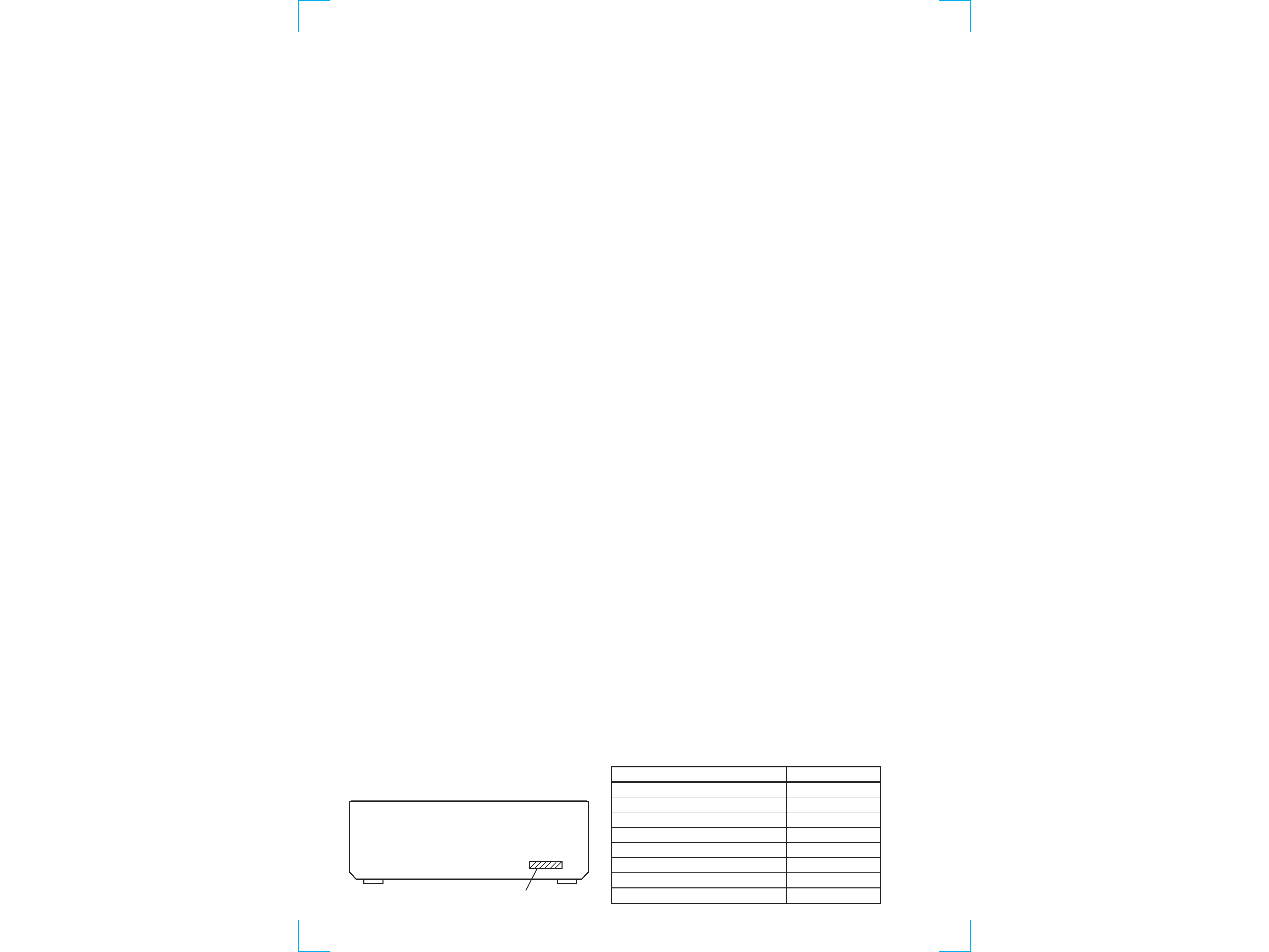
MODEL IDENTIFICATION
BACK PANEL
MODEL
DE835:
US model
DE835:
Singapore, Malaysia models
V828
DE835:
Australian model
DE835:
E, PX models
DE935
SE591
DE835:
Canadian model
PARTS No.
4-217-900-3
4-217-900-4
4-217-900-5
4-217-900-6
4-217-900-7
4-217-900-8
4-217-900-9
4-218-334-11
PART NO.
-- 3 --
SAFETY-RELATED COMPONENT WARNING!!
COMPONENTS IDENTIFIED BY MARK
! OR DOTTED LINE WITH
MARK
! ON THE SCHEMATIC DIAGRAMS AND IN THE PARTS
LIST ARE CRITICAL TO SAFE OPERATION. REPLACE THESE
COMPONENTS WITH SONY PARTS WHOSE PART NUMBERS
APPEAR AS SHOWN IN THIS MANUAL OR IN SUPPLEMENTS
PUBLISHED BY SONY.
ATTENTION AU COMPOSANT AYANT RAPPORT
À LA SÉCURITÉ!
LES COMPOSANTS IDENTIFÉS PAR UNE MARQUE
! SUR LES
DIAGRAMMES SCHÉMATIQUES ET LA LISTE DES PIÈCES SONT
CRITIQUES POUR LA SÉCURITÉ DE FONCTIONNEMENT. NE
REMPLACER CES COMPOSANTS QUE PAR DES PIÈSES SONY
DONT LES NUMÉROS SONT DONNÉS DANS CE MANUEL OU
DANS LES SUPPÉMENTS PUBLIÉS PAR SONY.
TABLE OF CONTENTS
SAFETY CHECK-OUT
(US model only)
After correcting the original service problem, perform the
following safety checks before releasing the set to the customer:
Check the antenna terminals, metal trim, "metallized" knobs, screws,
and all other exposed metal parts for AC leakage. Check leakage as
described below.
LEAKAGE
The AC leakage from any exposed metal part to earth ground
and from all exposed metal parts to any exposed metal part having
a return to chassis, must not exceed 0.5 mA (500 microampers).
Leakage current can be measured by any one of three methods.
1.
A commercial leakage tester, such as the Simpson 229 or RCA
WT-540A. Follow the manufacturers' instructions to use these
instruments.
2.
A battery-operated AC milliammeter. The Data Precision 245
digital multimeter is suitable for this job.
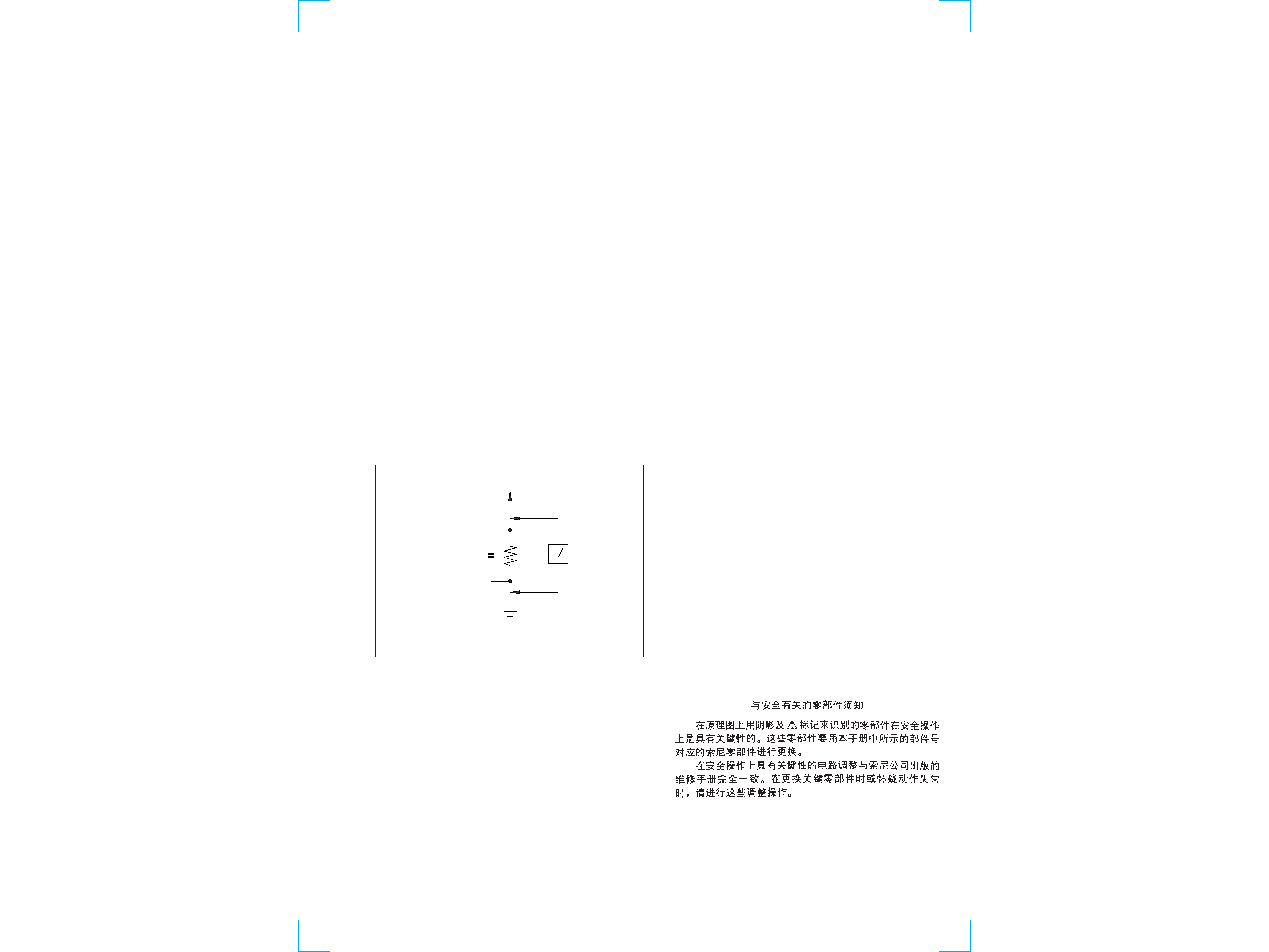
3.
Measuring the voltage drop across a resistor by means of a
VOM or battery-operated AC voltmeter. The "limit" indication
is 0.75 V, so analog meters must have an accurate low-voltage
scale. The Simpson 250 and Sanwa SH-63Trd are examples of
a passive VOM that is suitable. Nearly all battery operated
digital multimeters that have a 2V AC range are suitable. (See
Fig. A)
Earth Ground
AC
voltmeter
(0.75V)
1.5k
0.15
µF
Fig. A. Using an AC voltmeter to check AC leakage.
To Exposed Metal
Parts on Set
1. GENERAL ·········································································· 4
2. TEST MODE ······································································ 6
3. DIAGRAMS
3-1.
Block Diagram Main Section ··········································· 7
3-2.
Block Diagram Power Section ········································· 9
3-3.
Circuit Board Location ····················································· 11
3-4.
Schematic Diagram Digital Section(1/3) ······················· 13
3-5.
Schematic Diagram Digital Section(2/3) ······················· 15
3-6.
Schematic Diagram Digital Section(3/3) ······················· 17
3-7.
Printed Wiring Board Digital Section(1/2) ····················· 19
3-8.
Printed Wiring Board Digital Section(2/2) ····················· 21
3-9.
Printed Wiring Board Display Section ··························· 23
3-10. Schematic Diagram Display Section ······························ 25
3-11. Printed Wiring Board Surround Section ························· 27
3-12. Schematic Diagram Surround Section ··························· 29
3-13. Printed Wiring Board Rear AMP Section ······················· 31
3-14. Schematic Diagram Rear AMP Section ························· 33
3-15. Printed Wiring Board Power Section ····························· 35
3-16. Schematic Diagram Power Section ································ 37
3-17. Printed Wiring Board Video Section ······························ 39
3-18. Schematic Diagram Video Section ································· 41
3-19. Printed Wiring Board Main Section ······························· 43
3-20. Schematic Diagram Main Section(1/2) ·························· 45
3-21. Schematic Diagram Main Section(2/2) ·························· 47
3-22. IC Pin Function ································································ 49
3-23. IC Block Diagrams ··························································· 59
4. EXPLODED VIEWS
4-1.
Front Panel Section ·························································· 62
4-2.
Chassis Section ································································· 64
5. ELECTRICAL PARTS LIST ······································· 66
-- 4 --
SECTION 1
GENERAL
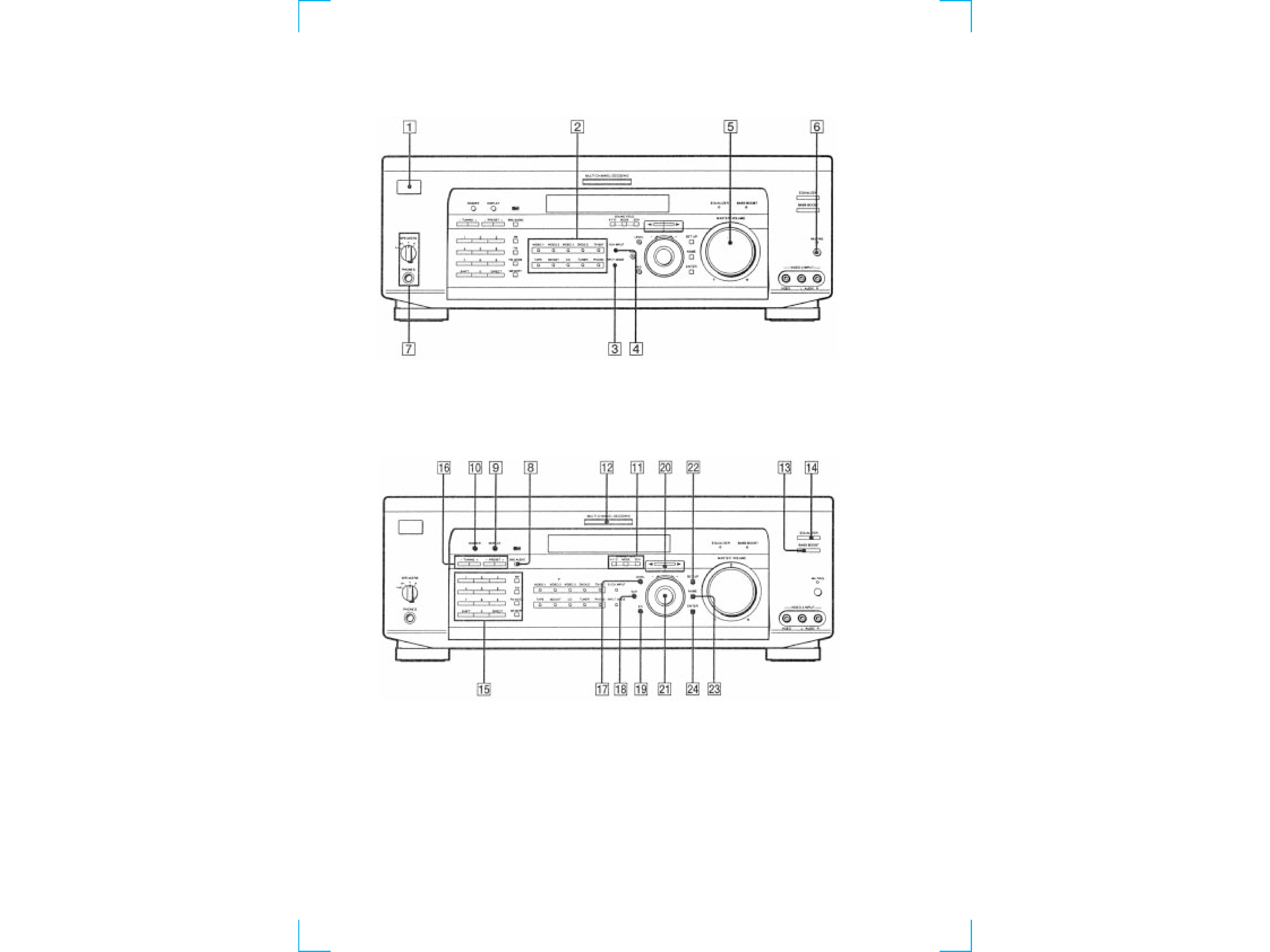
Identifying the Parts
Front Panel
1
1/u switch
2
Function buttons
3
INPUT MODE button
4
5.1CH INPUT button
5
MASTER VOLUME control
6
MUTING button
7
SPEAKERS selector
PHONES jack
8
2ND AUDIO button (DE935 MODEL)
9
DISPLAY button
0
DIMMER button
!¡
A.F.D button/indicator
MODE button/indicator
2CH button/indicator
!TM
MULTI CHANNEL DECODING indicator
!£
BASS BOOST button
!¢
EQUALIZER button
!
DIRECT button
SHIFT button
Numeric buttons (1 to 0)
AM button
FM button
FM MODE button
MEMORY button
!§
TUNNIG +/- buttons
PRESET +/- buttons
!¶
LEVEL button
!·
SUR button
!ª
EQ button
@º
Cursor buttons(</>)
@¡
Jog dial
@TM
SET UP button
@£
NAME button
@¢
ENTER button
-- 5 --
-- 6 --
SECTION 3
TEST MODE
FLUORESCENT INDICATOR TUBE TEST MODE
* All fluorescent segments are tested. When this test is activated,
all segments turn on at the same time, then each segment turns on
one after another.
* Procedure:
While depressing the ENTER, the LEVEL and the EQ buttons
simultaneously, press the power [
1/u] button to turn on the main
power. All segments turn on at the same time, then each segment
turns on press the ENTER button.
FACTORY SET MODE
* All preset contents are reset to the default setting.
* Procedure:
While depressing the SET UP, the LEVEL and the ENTER buttons
simultaneously, press the power [
1/u] button to turn on the main
power. The message Factry Set appears and the present contents
are reset to the default values.
ALL CLEAR MODE
* All preset contents are cleared when this mode is activated. Use
this mode before returning the product to clients upon completion
of repair.
* Procedure:
While depressing the SET UP button simultaneously, press the
power [
1/u] button to turn on the main power. The machine enters
the DEMO mode.DEMO mode: Wait a while, then the
demonstration starts. If the power [
1/u] button is pressed often
the demonstration has started, the power is turned off, and the
demonstration resumes if the power [
1/u] button is pressed again.
ALL CLEAR mode; If the power [
1/u] button is pressed often
the machine enters the DEMO mode, but before the demonstration
starts, the display is turned off. Press [
1/u] again. No response is
returned. The press [
1/u] again. The preset data is cleared and
the machine enters the normal power-on state.
SOUND FIELD CLEAR MODE
* The preset sound field is cleared when this mode is activated.
Use this mode before returning the product to clients upon
completion of repair.
* Procedure:
While depressing the SOUND FIELD MODE button, press the
power [
1/u] button to turn on the main power. The message S.F
Initialize appears and initialization is performed.
AM CHANNEL STEP 9 kHz/10 kHz
SELECTION MODE (US,Canadian Model)
* Either the 9 kHz step or 10 kHz step can be selected for the AM
channel step.
* Procedure:
Set the FUNCTION to AM. Turn off the main power.
While depressing the TUNING+ button or the PRESET TUNING
+ button, press the power [
1/u] button to turn on the main power.
Either the message AM 9kHz Step or AM 10kHz Step appears.
Select the desired step.
DSP TEST MODE
* It tests whether the DSP works correctly or not. When the DSP
test is activated, the test data is output from the DSP (IC1401:
CXD2712R) of the DIGITAL board and is written in the RAM
(IC1402: IDT71V016S). When the test data is read from the RAM
by the DSP, the data output must be equivalent to the original
data. If they disagree, an error is triggered. Errors can be caused
by the broken data line or defective soldering.
* Procedure
While pressing the SETUP, LEVEL and SUR buttons, press the
POWER button to enter the DSP test mode. The message DSP
TEST MODE appears. When an error occurs, the message DSP2
ERROR is displayed. When there is no error, the message DSP2
NO ERROR appears and the 1 kHz signal is output to all channels.
Then, the mode can be switched the (SIGN WAVE) (THROUGH)
and (INPULSE) mode.
VERSION MODE
* When this mode is used, the microprocessor version number is
displayed.
* Procedure:
Press the POWER button while pressing the ENTER, LEVEL,
and SUR buttons to turn on the power. The microprocessor version
number appears as follows.
SECTION 2
SERVICING NOTE
1. When the front panel is removed, the VR board is removed at the
same time. Consequently the LEDs cannot be turned on and the
sound volume cannot be increased or decreased from the remote
control.
2. When servicing the DIGITAL board, be sure to connect the earth
land of the DIGITAL board with the chassis frame so that the
earth potential of the DIGITAL board must not be floated from
the chassis frame.
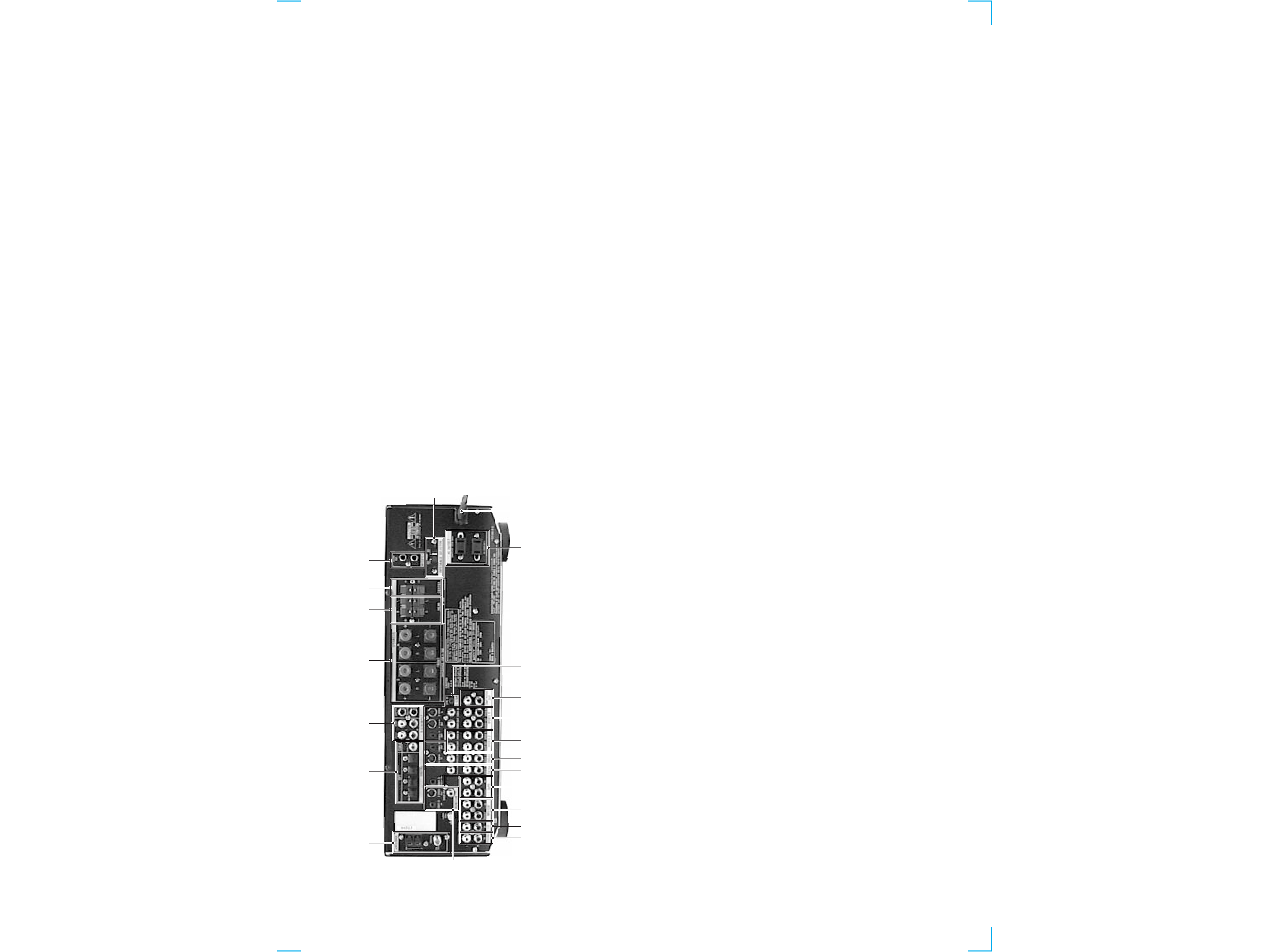
Rear Panel
1
2
3
4
5
6
7
9
0
8
!¡
!TM
!£
!¢
!
!§
!¶
!·
!ª
@º
@¡
1
ANTENNA
2
DIGITAL
3
5.1 CH INPUT
4
SPEAKERS (FRONT)
5
SPEAKERS (REAR)
6
SPEAKERS (CENTER)
7
WOOFER
8
INPEDANCE SELECTOR
9
AC power cord
!º
AC OUTLET
!¡
S-LINK
!TM
2ND AUDIO OUT
!£
VIDEO 1
!¢
VIDEO 2
!
DVD/LD
(US, Canadian, Australian models)
DVD
(EXCEPT US, Canadian, Australian models)
!§
TV/SAT
(US, Canadian, Australian models)
TV/LD
(EXCEPT US, Canadian, Australian models)
!¶
TAPE (DE935 MODEL)
!·
MD/DAT (DE935 MODEL)
MD/TAPE (EXCEPT DE935)
!ª
CD
@º
PHONO
@¡
MONITOR