
model name1[STR-DE597]
[4-252-271-12(1)]
lename[C:\Data\Sony SEM_Janet\STR-
DE597_Data\J904000_4252271121DE597UCA\4252271121\4252271121DE597UCA\GB01CO
V_STR-DE597-UCA.fm]
masterpage:Right
©2004 Sony Corporation
4-252-271-12(1)
FM Stereo
FM/AM Receiver
Operating Instructions
Owner's Record
The model and serial numbers are located on the rear of the unit. Record the serial
number in the space provided below. Refer to them whenever you call upon your
Sony dealer regarding this product.
Model No.
Serial No.
STR-DE597
GB01COV_STR-DE597-UCA.book Page 1 Monday, March 8, 2004 12:15 PM
masterpage:Left
lename[C:\Data\Sony SEM_Janet\STR-
DE597_Data\J904000_4252271121DE597UCA\4252271121\4252271121DE597UCA\GB02RE
G_STR-DE597-UCA.fm]
model name1[STR-DE597]
[4-252-271-12(1)]
2GB
To prevent fire or shock hazard, do not
expose the unit to rain or moisture.
To prevent fire, do not cover the ventilation of the
apparatus with newspapers, table-cloths, curtains, etc.
And don't place lighted candles on the apparatus.
To prevent fire or shock hazard, do not place objects
filled with liquids, such as vases, on the apparatus.
Don't throw away batteries with
general house waste; dispose of
them correctly as chemical waste.
For customers in the United States
This symbol is intended to alert
the user to the presence of
uninsulated "dangerous voltage"
within the product's enclosure
that may be of sufficient
magnitude to constitute a risk of
electric shock to persons.
This symbol is intended to alert
the user to the presence of
important operating and
maintenance (servicing)
instructions in the literature
accompanying the appliance.
WARNING
This equipment has been tested and found to comply with the
limits for a Class B digital device, pursuant to Part 15 of the
FCC Rules. These limits are designed to provide reasonable
protection against harmful interference in a residential
installation. This equipment generates, uses, and can radiate
radio frequency energy and, if not installed and used in
accordance with the instructions, may cause harmful
interference to radio communications. However, there is no
guarantee that interference will not occur in a particular
installation. If this equipment does cause harmful
interference to radio or television reception, which can be
determined by turning the equipment off and on, the user is
encouraged to try to correct the interference by one or more
of the following measures:
Reorient or relocate the receiving antenna.
Increase the separation between the equipment and
receiver.
Connect the equipment into an outlet on a circuit
different from that to which the receiver is
connected.
Consult the dealer or an experienced radio/TV
technician for help.
CAUTION
You are cautioned that any changes or modification not
expressly approved in this manual could void your
authority to operate this equipment.
Note to CATV system installer:
This reminder is provided to call CATV system
installer's attention to Article 820-40 of the NEC that
provides guidelines for proper grounding and, in
particular, specifies that the cable ground shall be
connected to the grounding system of the building, as
close to the point of cable entry as practical.
For customers in Canada
CAUTION
TO PREVENT ELECTRIC SHOCK, MATCH WIDE
BLADE OF PLUG TO WIDE SLOT, FULLY
INSERT.
Except for customers in Europe
ENERGY STAR® is a U.S.
registered mark. As an ENERGY
STAR® partner, Sony Corporation
has determined that this product
meets the ENERGY STAR®
guidelines for energy efficiency.
WARNING
Do not install the appliance in a confined space,
such as a bookcase or built-in cabinet.
GB01COV_STR-DE597-UCA.book Page 2 Monday, March 8, 2004 12:15 PM
masterpage:Right
lename[C:\Data\Sony SEM_Janet\STR-
DE597_Data\J904000_4252271121DE597UCA\4252271121\4252271121DE597UCA\GB02RE
G_STR-DE597-UCA.fm]
model name1[STR-DE597]
[4-252-271-12(1)]
3GB
About This Manual
· The instructions in this manual are for model
STR-DE597. Check your model number by looking
at the lower right corner of the front panel.
· The instructions in this manual describe the controls
on the receiver. You can also use the controls on the
supplied remote if they have the same or similar
names as those on the receiver. For details on the use
of your remote, see pages 4245.
This receiver incorporates Dolby* Digital and Pro
Logic Surround and the DTS** Digital Surround
System.
* Manufactured under license from Dolby
Laboratories.
"Dolby", "Pro Logic" and the double-D symbol are
trademarks of Dolby Laboratories.
**"DTS", "DTS-ES", "Neo:6" and "DTS 96/24" are
trademarks of Digital Theater Systems, Inc.
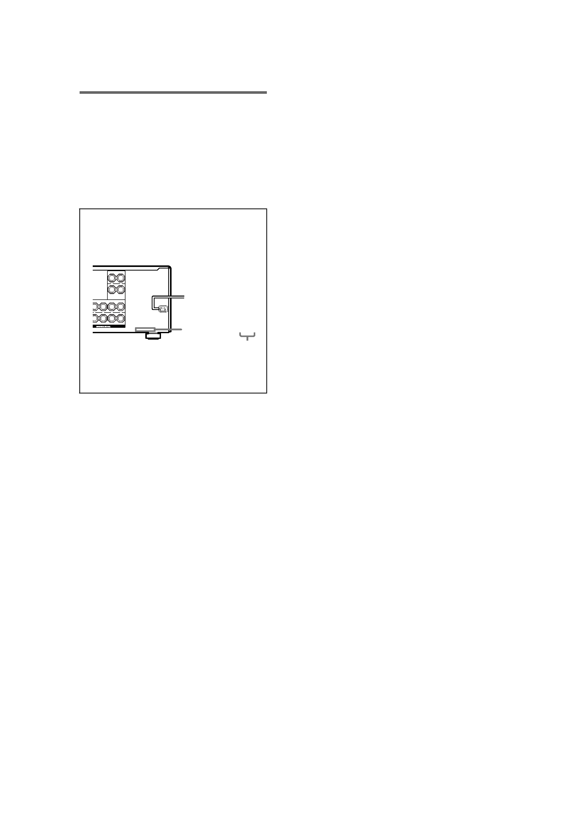
About area codes
The area code of the receiver you purchased is
shown on the lower portion of the rear panel (see
the illustration below).
Any differences in operation, according to the area
code, are clearly indicated in the text, for example,
"Models of area code AA only".
SURROUND
FRONT A
CENTER
RS
L
R
L
R
SURROUND BACK
+
+
+
AC OUTLET
4-XXX-XXX-XX AA
Area code
GB01COV_STR-DE597-UCA.book Page 3 Monday, March 8, 2004 12:15 PM
masterpage:Left
lename[C:\Data\Sony SEM_Janet\STR-
DE597_Data\J904000_4252271121DE597UCA\4252271121\4252271121DE597UCA\GB01CO
V_STR-DE597-UCATOC.fm]
model name1[STR-DE597]
[4-252-271-12(1)]
4GB
Getting Started
1: Check how to hookup your
components ....................................... 5
1a: Connecting components with
digital audio output jacks ........... 7
1b: Connecting components with
multi channel output jacks........ 10
1c: Connecting components with
only analog audio jacks ............ 12
2: Connecting the antennas ................... 14
3: Connecting speakers ......................... 15
4: Connecting the AC power cord ........ 17
5: Setting up the speakers ..................... 18
6: Adjusting the speaker levels and
balance ............................................ 21
-- TEST TONE
Amplifier Operation
Selecting the component ....................... 22
Listening to multi channel sound.......... 23
-- MULTI CH IN
Listening to FM/AM radio.................... 23
Storing FM stations automatically ........ 24
-- AUTOBETICAL
(Models of area code CEL, CEK
only)
Presetting radio stations ........................ 25
Using the Radio Data System (RDS).... 26
(Models of area code CEL, CEK
only)
Changing the display............................. 27
About the indications in the display...... 28
Enjoying Surround Sound
Using only the front speakers ............... 30
Enjoying higher fidelity sound.............. 30
-- AUTO FORMAT DIRECT
Selecting a sound field .......................... 31
Selecting the surround back decoding
mode ............................................... 33
-- SURR BACK DECODING
Advanced Adjustments and
Settings
Switching the audio input mode for
digital components ......................... 35
-- INPUT MODE
Customizing sound fields ..................... 35
Adjusting the tone................................. 37
Advanced settings................................. 37
Other Operations
Naming preset stations and inputs ........ 39
Using the Sleep Timer .......................... 40
Selecting the speaker system ................ 40
Recording ............................................. 41
Operations Using the Remote
RM-U306B
Before you use your remote.................. 42
Remote button description.................... 42
Changing the factory setting of an
input button .................................... 45
Additional Information
Precautions ........................................... 46
Troubleshooting.................................... 47
Specifications ....................................... 49
List of button locations and reference
pages............................................... 52
Index ..................................................... 53
Table of Contents
GB01COV_STR-DE597-UCA.book Page 4 Monday, March 8, 2004 12:15 PM
Getting
Star
ted
masterpage:Right
lename[C:\Data\Sony SEM_Janet\STR-
DE597_Data\J904000_4252271121DE597UCA\4252271121\4252271121DE597UCA\GB03CO
N_STR-DE597-UCA.fm]
model name1[STR-DE597]
[4-252-271-12(1)]
5GB
Steps 1a through 1c beginning on page 7 describe how to hook up your components to this receiver.
Before you begin, refer to "Connectable components" below for the pages which describe how to
connect each component.
After hooking up all your components, proceed to "2: Connecting the antennas" (page 14).
Connectable components
a) Model with a DIGITAL OPTICAL OUTPUT or DIGITAL COAXIAL OUTPUT jack, etc.
b) Model with a MULTI CH OUTPUT jacks, etc. This connection is used to output the audio decoded by the
component's internal multi channel decoder through this receiver.
c) Model equipped only with AUDIO OUT L/R jacks, etc.
d) Model with component video (Y, P
B/CB/B-Y, PR/CR/R-Y) input jacks.
Getting Started
1: Check how to hookup your components
Component to be connected
Page
DVD player
With digital audio outputa)
78
With multi channel audio outputb)
1011
With analog audio output onlyc)
78
TV monitor
With component video inputd)
8 or 11
With composite video input only
13
Satellite tuner
With digital audio outputa)
78
With analog audio output onlyc)
78
Super Audio CD/CD player
With digital audio outputa)
9
With multi channel audio outputb)
10
With analog audio output onlyc)
12
MD/Tape deck
With analog audio output onlyc)
12
Multi channel decoder
10
VCR
13
continued
GB01COV_STR-DE597-UCA.book Page 5 Monday, March 8, 2004 12:15 PM