4-233-503-13(3)
FM Stereo
FM-AM Receiver
Operating Instructions
© 2001 Sony Corporation
STR-DE475
STR-K402
Owner's Record
The model and serial numbers are located on the rear of the unit. Record the serial number in the space
provided below. Refer to them whenever you call upon your Sony dealer regarding this product.
Model No. STR-DE475/K402
Serial No.
2
WARNING
To prevent fire or shock
hazard, do not expose the
unit to rain or moisture.
This symbol is intended to alert the user to
the presence of uninsulated "dangerous
voltage" within the product's enclosure
that may be of sufficient magnitude to
constitute a risk of electric shock to
persons.
This symbol is intended to alert the user to
the presence of important operating and
maintenance (servicing) instructions in the
literature accompanying the appliance.
INFORMATION
This equipment has been tested and found
to comply with the limits for a Class B
digital device, pursuant to Part 15 of the
FCC Rules.
These limits are designed to provide
reasonable protection against harmful
interference in a residential installation.
This equipment generates, uses, and can
radiate radio frequency energy and, if not
installed and used in accordance with the
instructions, may cause harmful
interference to radio communications.
However, there is no guarantee that
interference will not occur in a particular
installation. If this equipment does cause
harmful interference to radio or television
reception, which can be determined by
turning the equipment off and on, the user
is encouraged to try to correct the
interference by one or more of the
following measures:
Reorient or relocate the receiving antenna.
Increase the separation between the
equipment and receiver.
Connect the equipment into an outlet on a
circuit different from that to which the
receiver is connected.
Consult the dealer or an experienced radio/
TV technician for help.
CAUTION
You are cautioned that any changes or
modification not expressly approved in
this manual could void your authority to
operate this equipment.
Note to CATV system installer:
This reminder is provided to call CATV
system installer's attention to Article 820-
40 of the NEC that provides guidelines for
proper grounding and, in particular,
specifies that the cable ground shall be
connected to the grounding system of the
building, as close to the point of cable
entry as practical.
Owner's Record
The model and serial numbers are located
on the rear of the unit. Record the serial
number in the space provided below.
Refer to them whenever you call upon
your Sony dealer regarding this product.
Model No. STR-DE475/K402
Serial No.
For customers in Canada
CAUTION
TO PREVENT ELECTRIC SHOCK, DO
NOT USE THIS POLARIZED AC PLUG
WITH AN EXTENSION CORD,
RECEPTACLE OR OTHER OUTLET
UNLESS THE BLADES CAN BE FULLY
INSERTED TO PREVENT BLADE
EXPOSURE.
For customers in the United States and
Canada
ENERGY STAR® is a U.S.
registered mark.
As an ENERGY STAR® partner,
Sony Corporation has
determined that this product
meets the ENERGY STAR®
guidelines for energy
efficiency
For customers in other countries
To avoid electrical shock,
do not open the cabinet.
Refer servicing to qualified
personnel only.
Do not install the
appliance in a confined
space, such as a bookcase
or built-in cabinet.
Precautions
On safety
· Should any solid object or liquid fall into the
cabinet, unplug the receiver and have it
checked by qualified personnel before
operating it any further.
· To prevent fire, do not cover the ventilation
of the receiver with newspapers, table cloths,
curtains, etc. And don't place lighted candles
on the receiver.
· To prevent fire or shock hazards, do not place
vases on the receiver.
On power sources
· Before operating the receiver, check that the
operating voltage is identical with your local
power supply. The operating voltage is
indicated on the nameplate at the rear of the
receiver.
· The unit is not disconnected from the AC
power source (mains) as long as it is
connected to the wall outlet, even if the unit
itself has been turned off.
· If you are not going to use the receiver for a
long time, be sure to disconnect the receiver
from the wall outlet. To disconnect the AC
power cord, grasp the plug itself; never pull
the cord.
· One blade of the plug is wider than the other
for the purpose of safety and will fit into the
wall outlet only one way. If you are unable to
insert the plug fully into the outlet, contact
your dealer. (for customers in the United
States and Canada only)
· AC power cord must be changed only at the
qualified service shop.
On placement
· Place the receiver in a location with adequate
ventilation to prevent heat buildup and
prolong the life of the receiver.
· Do not place the receiver near heat sources,
or in a place subject to direct sunlight,
excessive dust or mechanical shock.
· Do not place anything on top of the cabinet
that might block the ventilation holes and
cause malfunctions.
· Although the receiver heats up during
operation, this is not a malfunction. If you
continuously use this receiver at a large
volume, the cabinet temperature of the top,
side and bottom rises accordingly. To avoid
burning yourself, do not touch the cabinet.
On operation
Before connecting other components, be
sure to turn off and unplug the receiver.
On cleaning
Clean the cabinet, panel and controls with
a soft cloth slightly moistened with a mild
detergent solution. Do not use any type of
abrasive pad, scouring powder or solvent
such as alcohol or benzine.
If you have any question or problem
concerning your receiver, please
consult your nearest Sony dealer.
For customers in the United States
3
About This Manual
The instructions in this manual are for models
STR-DE475 and STR-K402. Check your model number by
looking at the lower right corner of the front panel.
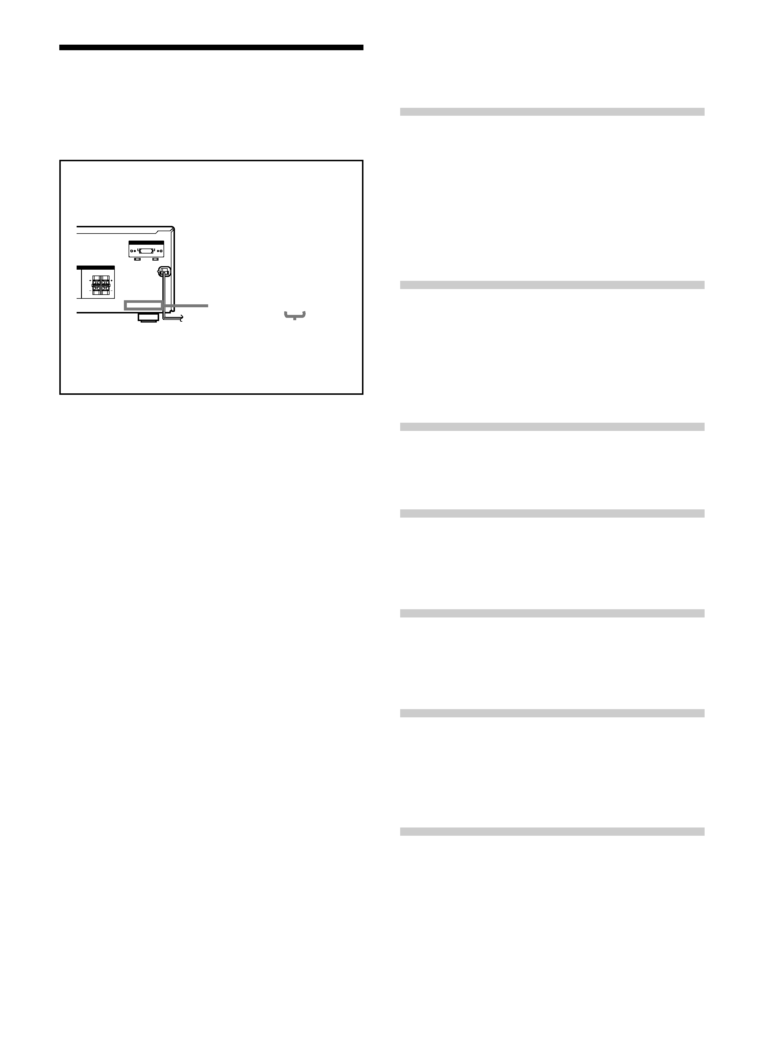
About area codes
The area code of the player you purchased is shown on the
lower portion of the rear panel (see the illustration below).
Any differences in operation, according to the area code, are
clearly indicated in the text, for example, "Models of area
code AA only".
Conventions
· The instructions in this manual describe the controls on
the receiver. You can also use the controls on the
supplied remote if they have the same or similar names
as those on the receiver.
· The following icon is used in this manual:
z
Indicates hints and tips for making the task easier.
This receiver incorporates Dolby
* Digital and Pro Logic
Surround and the DTS** Digital Surround System.
* Manufactured under license from Dolby Laboratories.
"Dolby", "AC-3", "Pro Logic" and the double-D symbol a are
trademarks of Dolby Laboratories.
Confidential unpublished Works. © 1992-1997 Dolby Laboratories.
All rights reserved.
**Manufactured under license from Digital Theater Systems, Inc. US
Pat. No. 5,451,942, 5,956,674, 5,974,380, 5,978,762 and other
world-wide patents issued and pending. "DTS" and "DTS Digital
Surround" are registered trademarks of Digital Theater Systems, Inc.
Copyright 1996, 2000 Digital Theater Systems, Inc. All Rights
Reserved.
TABLE OF CONTENTS
Hooking Up the Components
4
Unpacking 4
Antenna Hookups 5
Audio Component Hookups 6
Video Component Hookups 7
Digital Component Hookups 8
MULTI CH IN Hookups 9
Other Hookups 10
Hooking Up and Setting Up the
Speaker System
11
Speaker System Hookup 12
Performing Initial Setup Operations 14
Multi Channel Surround Setup 15
Before You Use Your Receiver 19
Location of Parts and Basic
Operations
21
Front Panel Parts Descriptions 21
Enjoying Surround Sound
24
Selecting a Sound Field 25
Understanding the Multi-Channel Surround Displays 28
Customizing Sound Fields 30
Receiving Broadcasts
34
Direct Tuning 36
Automatic Tuning 36
Preset Tuning 37
Other Operations
38
Naming Preset Stations and Program Sources 39
Recording 39
Using the Sleep Timer 40
Adjustment Using the SET UP Button 41
Additional Information
42
Troubleshooting 42
Specifications 44
Glossary 46
Settings Using SURR, LEVEL, and SET UP buttons 47
Remote Button Description 48
Index 51
FRONT
120V
240V
220V
CENTER
RL
RL
VOLTAGE SELECTOR
VOLTAGE SELECTOR
RS
RS
IMPEDANCE USE 8 16
IMPEDANCE USE 8 16
4-XXX-XXX-XX AA
Area code
4
Hooking Up
the
Components
This chapter describes how to connect
various audio and video components
to the receiver. Be sure to read the
sections for the components you have
before you actually connect them to
the receiver.
Unpacking
Check that you received the following items with the
receiver:
· FM wire antenna (1)
· AM loop antenna (1)
· R6 (size-AA) batteries (2)
· Remote Commander (remote) (1)
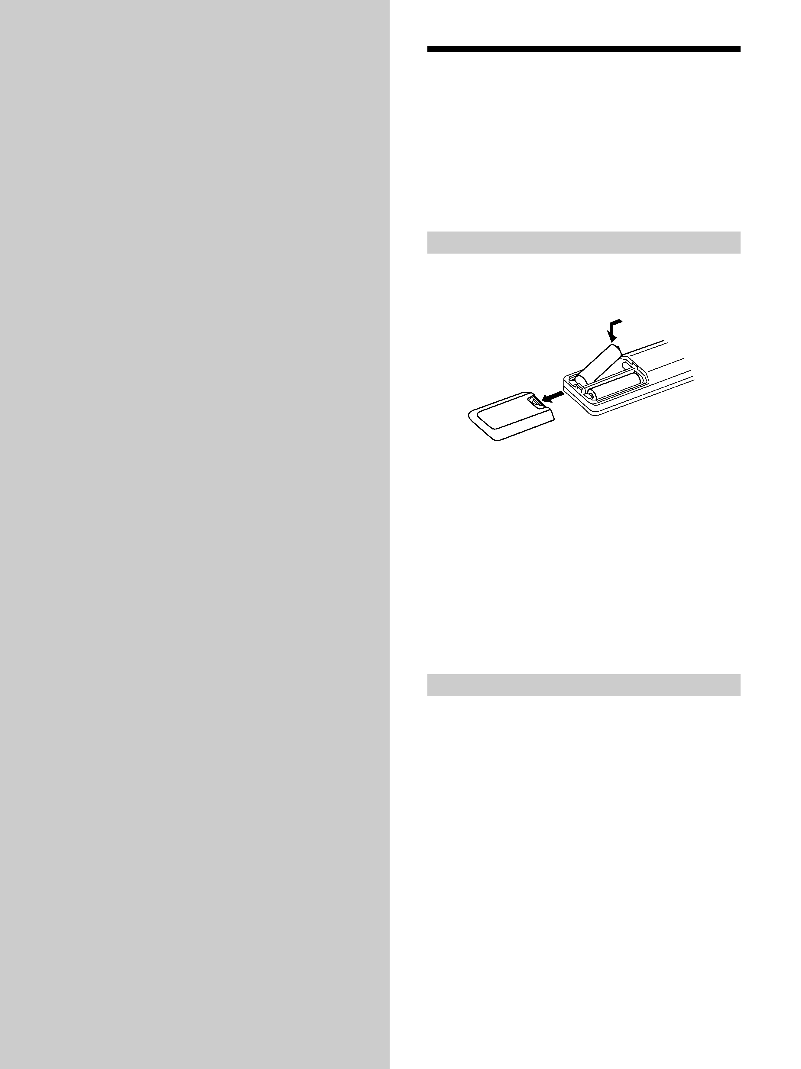
Inserting batteries into the remote
Insert R6 (size-AA) batteries with the + and properly
oriented in the battery compartment. When using the
remote, point it at the remote sensor g on the receiver.
z When to replace batteries
Under normal conditions, the batteries should last for about 6
months. When the remote no longer operates the receiver, replace
all batteries with new ones.
Notes
· Do not leave the remote in an extremely hot or humid place.
· Do not use a new battery with an old one.
· Do not expose the remote sensor to direct sunlight or lighting
apparatuses. Doing so may cause a malfunction.
· If you don't use the remote for an extended period of time,
remove the batteries to avoid possible damage from battery
leakage and corrosion.
Before you get started
· Turn off the power to all components before making
any connections.
· Do not connect the AC power cords until all of the
connections are completed.
· Be sure to make connections firmly to avoid hum and
noise.
· When connecting an audio/video cord, be sure to
match the color-coded pins to the appropriate jacks on
the components: yellow (video) to yellow; white (left,
audio) to white; and red (right, audio) to red.
}
}
]
]
5
Hooking
Up
the
System
SUB
WOOFER
IN
OUT
IN
AUDIO IN
AUDIO IN
AUDIO OUT
AUDIO
OUT
FRONT
CENTER
SURROUND
AUDIO IN
RL
RL
RL
RL
MULTI CH IN
MULTI CH IN
DIGITAL
DIGITAL
ANTENNA
CD
CD
MD/TAPE
MD/TAPE
VIDEO
VIDEO
SPEAKERS
SPEAKERS
FRONT
TV/SAT
IN
OPTICAL
DVD/LD
IN
SURROUND
R
L
R
L
CENTER
VIDEO IN
VIDEO IN
VIDEO OUT
VIDEO IN
VIDEO OUT
IMPEDANCE USE 8 16
IMPEDANCE USE 8 16
ANTENNA
ANTENNA
AM
FM
75
COAXIAL
TV/SAT
TV/SAT
MONITOR
DVD/LD
DVD/LD
SUB
WOOFER
SUB
WOOFER
COAXIAL
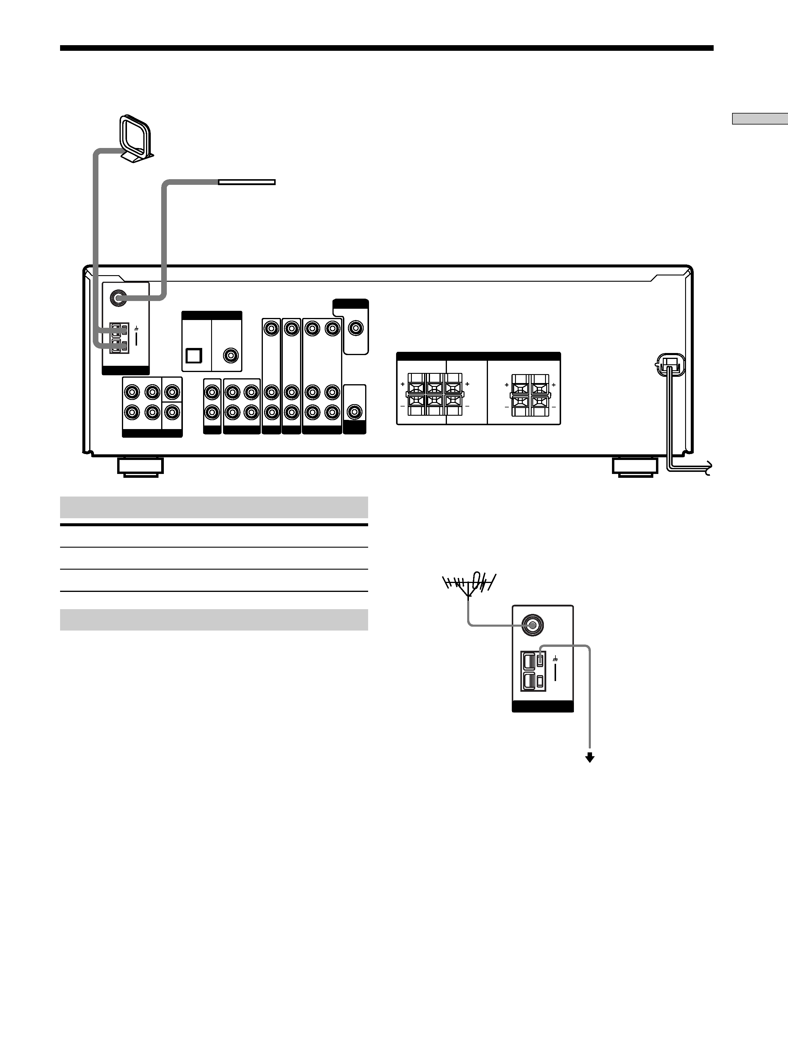
FM wire antenna
(supplied)
AM loop antenna
(supplied)
Terminals for connecting the antennas
Connect the
To the
AM loop antenna
AM terminals
FM wire antenna
FM 75
COAXIAL terminal
Antenna Hookups
ANTENNA
AM
FM
75
COAXIAL
Important
If you connect the receiver to an outdoor antenna, ground
it against lightning. To prevent a gas explosion, do not
connect the ground wire to a gas pipe.
Notes on antenna hookups
· To prevent noise pickup, keep the AM loop antenna
away from the receiver and other components.
· Be sure to fully extend the FM wire antenna.
· After connecting the FM wire antenna, keep it as
horizontal as possible.
Ground wire
(not supplied)
To ground
z If you have poor FM reception
Use a 75-ohm coaxial cable (not supplied) to connect the receiver
to an outdoor FM antenna as shown below.
Receiver
Outdoor FM antenna