STR-DE375
Canadian Model
AEP Model
UK Model
E Model
SERVICE MANUAL
FM STEREO FM-AM RECEIVER
Sony Corporation
Audio Entertainment Group
General Engineering Dept.
9-873-861-11
2001D1600-1
© 2001.4
-- Continued on next page --
SPECIFICATIONS
Ver 1.0 2001. 04
Manufactured under license from Dolby Laboratories Licensing
Corporation.
"DOLBY" the double-D symbol ; "AC-3" and "Pro Logic" are
trademarks of Dolby Laboratories Licensing Corporation.
Amplifier section
Rated Power
Output at Stereo
Mode
Reference Power
Output
Frequency
response
Inputs
Tuning range
Antenna terminals
Intermediate
frequency
Sensitivity
Usable sensitivity
S/N
Harmonic
distortion at
1 kHz
Tuner section
FM stereo, FM/AM superheterodyne tuner
FM tuner section
87.5 - 108.0 MHz
75 ohms, unbalanced
10.7 MHz
Mono: 18.3 dBf, 4.5
µV
Stereo: 38.3 dBf, 45
µV
11.2 dBf, 1
µV (IHF)
Mono: 76 dB
Stereo: 70 dB
Mono: 0.3 %
Stereo: 0.5 %
Outputs
Muting
TONE
MD/TAPE OUT:
Voltage: 150 mV,
Impedance: 10 kilohms
VIDEO AUDIO OUT:
Voltage: 150 mV,
Impedance: 10 kilohms
SUB WOOFER:
Voltage: 2 V
Impedance: 1 kilohms
PHONES: Accepts low
and high impedance
headphones
Full mute
±6 dB at 100 Hz and
10 kHz
CD,
DVD/
MULTI CH,
MD/TAPE,
TV/SAT,
VIDEO
Sensitivity
150 mV
Impedance
50
kilohms
S/N
85 dB
+0.5
2
Canadian model:
(8 ohms 40 Hz - 20 kHz,
less than 0.09% total
harmonic distortion)
80 W + 80 W
Malaysia, Singapore model
(8 ohms at 1 kHz, THD
0.7%)
80 W + 80 W
Other countries:
(8 ohms at 1 kHz, THD
0.7%)
50 W + 50 W
Canadian model:
(8 ohms at 1 kHz, THD
0.7%)
Front: 80 W/ch
Center: 80 W
Surround: 80 W/ch
Malaysia, Singapore model
(8 ohm at 1 kHz, THD 10%)
Front: 90 W/ch
Center: 90 W
Surround: 80 W/ch
Other countries:
(8 ohms at 1 kHz, THD
10%)
Front: 50 W/ch
Center: 50 W
Surround: 50 W/ch
TV/SAT, CD, MD/TAPE,
VIDEO, DVD/MULTI
CH: 10 Hz - 50 kHz
dB
2
STR-DE375
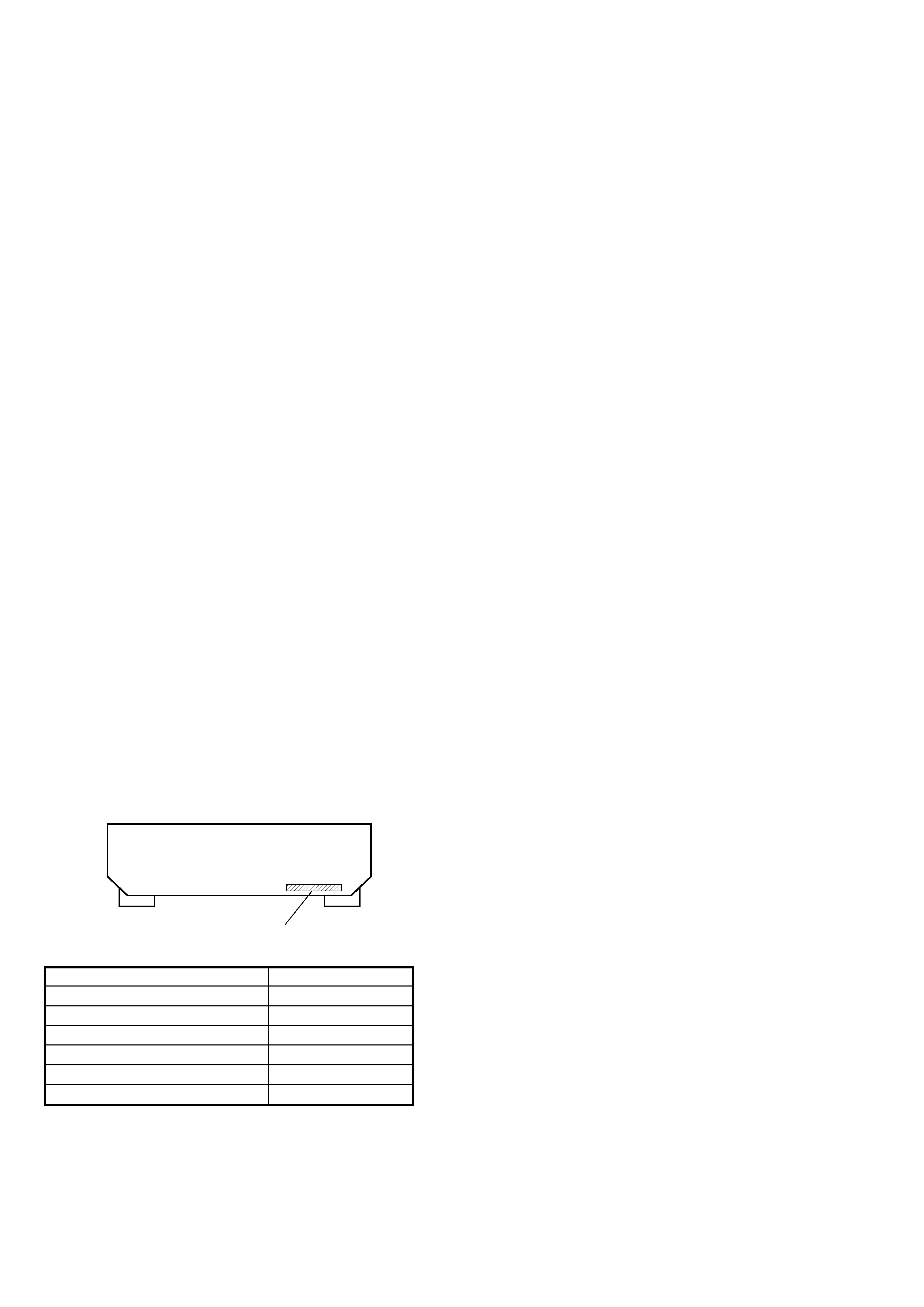
MODEL IDENTIFICATION
-- BACK PANEL --
Parts No.
MODEL
PARTS No.
AEP model
4-232-119-0s
UK model
4-232-119-1s
Malaysia,Singapore model
4-232-119-3s
E model
4-232-119-4s
Canadian model
4-232-119-5s
Argentina model
4-232-119-7s
System
Power
requirements
Power
consumption
Dimensions
Mass(Approx.)
Supplied
accessories
Tuner section: PLL
quartz-locked digital
synthesizer system
Preamplifier section:
Low-noise NF type
equalizer
Power amplifier section:
Pure-complementary
SEPP
Canadian model:
120 V AC, 60 Hz
Malaysia, Singapore model
220-230 V AC,
50/60 Hz
Other countries:
120/220/240 V AC,
50/60 Hz
Canadian model:
240 VA
Standby mode: 0.5 W
Malaysia, Singapore model
175 W
Standby mode: 0.5 W
Other countries:
160 W
Standby mode: 0.5 W
430 x 145 x 298 mm
Malaysia, Singapore model
5.5 kg
Canadian and other
countries:
6 kg (13 lb 4 oz)
General
The specification measured
is under
· 230 AC 50 Hz condition
(Malaysia, Singapore model)
Design and specifications are
subject to change without notice.
· FM wire antenna (1)
· AM loop antenna (1)
· Remote commander
(remote) (1)
· Size AA (R6) batteries (2)
* You can change the AM tuning interval
between 9 kHz and 10 kHz. Turn off the
receiver and press ?/1 (power) for more
than 4 seconds until "INITIAL" appears.
1) After tuning in any AM station, turn
off the receiver.
2) Hold down PRESET TUNING +
button and press the ?/1 (power)
button. "9k STEP" appears.
To change to 10k Step, repeat step 1 and 2
until "10k STEP" appears. Note that all
preset stations, index names and sound
field are cleared after you make the
procedure above.
Separation
Frequency
response
Selectivity
+0.5
2
AM tuner section
45 dB at 1 kHz
30 Hz - 15 kHz
dB
60 dB at 400 kHz
Tuning range
Antenna
Intermediate
frequency
Usable sensitivity
S/N
Harmonic
distortion
Selectivity
Malaysia, Singapore model
531 - 1602 kHz (9 kHz
step)
Canadian model:
530 - 1710 kHz (10 kHz
step)*
531 - 1710 kHz (9 kHz
step)*
Other countries models:
530 - 1610 kHz (10 kHz
step)*
531 - 1602 kHz (9 kHz
step)*
Loop antenna
450 kHz
50 dB/m (at 999 kHz)
54 dB (at 50 mV/m)
0.5 % (50 mV/m, 400 Hz)
At 9 kHz: 35 dB
At 10 kHz: 40 dB
3
STR-DE375
SAFETY-RELATED COMPONENT WARNING!!
COMPONENTS IDENTIFIED BY MARK 0 OR DOTTED LINE WITH
MARK 0 ON THE SCHEMATIC DIAGRAMS AND IN THE PARTS
LIST ARE CRITICAL TO SAFE OPERATION. REPLACE THESE
COMPONENTS WITH SONY PARTS WHOSE PART NUMBERS
APPEAR AS SHOWN IN THIS MANUAL OR IN SUPPLEMENTS
PUBLISHED BY SONY.
After correcting the original service problem, perform the
following safety checks before releasing the set to the customer:
Check the antenna terminals, metal trim, "metallized" knobs, screws,
and all other exposed metal parts for AC leakage. Check leakage as
described below.
LEAKAGE
The AC leakage from any exposed metal part to earth ground and
from all exposed metal parts to any exposed metal part having a
return to chassis, must not exceed 0.5 mA (500 microamperes).
Leakage current can be measured by any one of three methods.
1.
A commercial leakage tester, such as the Simpson 229 or RCA
WT-540A. Follow the manufacturers' instructions to use these
instruments.
2.
A battery-operated AC milliammeter. The Data Precision 245
digital multimeter is suitable for this job.
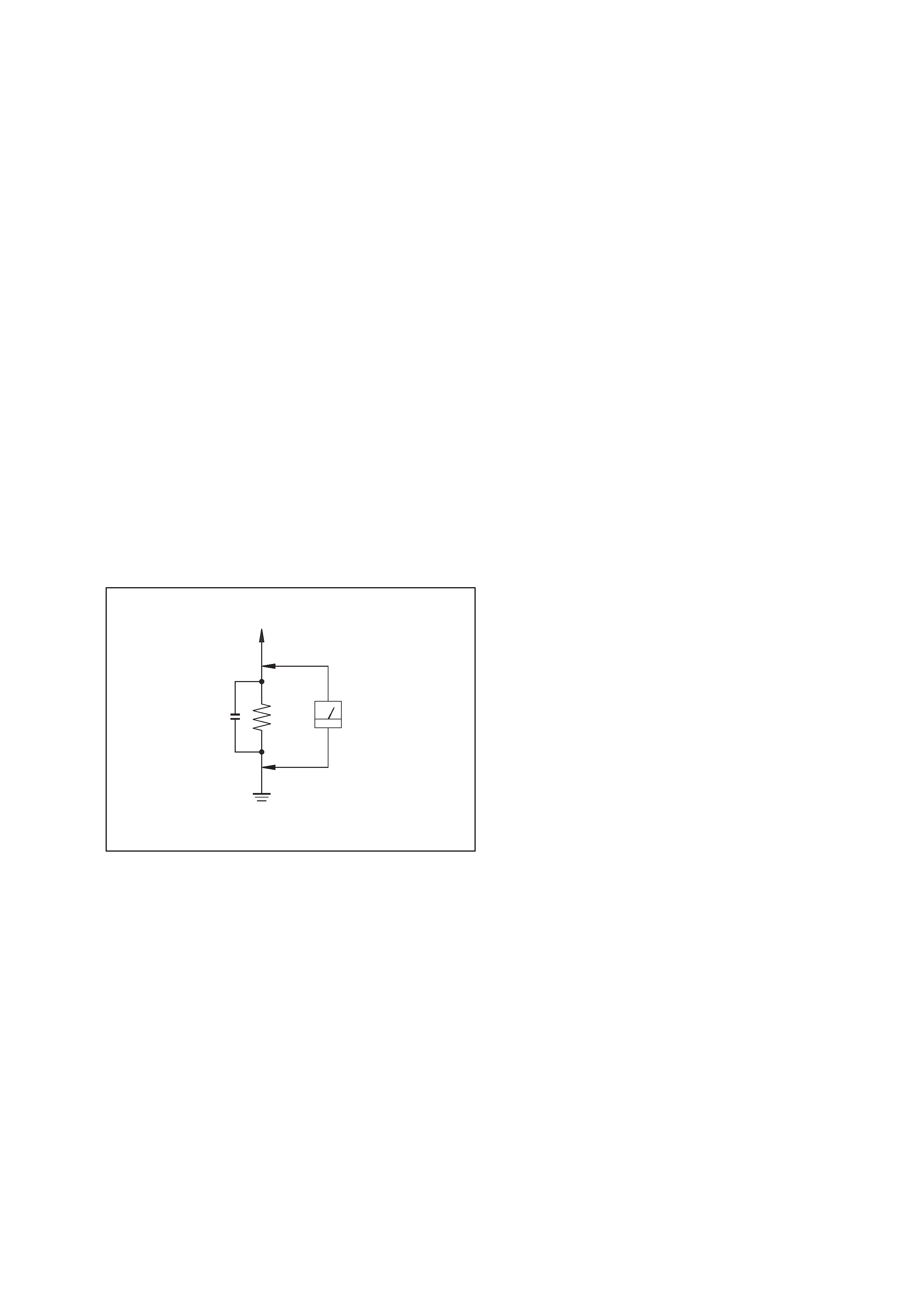
3.
Measuring the voltage drop across a resistor by means of a
VOM or battery-operated AC voltmeter. The "limit" indication
is 0.75 V, so analog meters must have an accurate low-voltage
scale. The Simpson 250 and Sanwa SH-63Trd are examples of
a passive VOM that is suitable. Nearly all battery operated
digital multimeters that have a 2V AC range are suitable. (See
Fig. A)
SAFETY CHECK-OUT
To Exposed Metal
Parts on Set
0.15
µF
1.5 k
AC
Voltmeter
(0.75 V)
Earth Ground
Fig. A. Using an AC voltmeter to check AC leakage.
ATTENTION AU COMPOSANT AYANT RAPPORT
À LA SÉCURITÉ!
LES COMPOSANTS IDENTIFÉS PAR UNE MARQUE 0 SUR LES
DIAGRAMMES SCHÉMATIQUES ET LA LISTE DES PIÈCES SONT
CRITIQUES POUR LA SÉCURITÉ DE FONCTIONNEMENT. NE
REMPLACER CES COMPOSANTS QUE PAR DES PIÈSES SONY
DONT LES NUMÉROS SONT DONNÉS DANS CE MANUEL OU
DANS LES SUPPÉMENTS PUBLIÉS PAR SONY.
TABLE OF CONTENTS
1. GENERAL ·········································································· 4
2. TEST MODE ······································································ 6
3. DIAGRAMS
3-1.
Circuit Boards Location ····················································· 7
3-2.
Block Diagram ··································································· 9
3-3.
Printed Wiring Board Main Section ······························· 10
3-4.
Schematic Diagram Main Section (1/3) ························· 11
3-5.
Schematic Diagram Main Section (2/3) ························· 12
3-6.
Schematic Diagram Main Section (3/3) ························· 13
3-7.
Printed Wiring Board Panel Section ······························· 14
3-8.
Schematic Diagram
Panel Section ································ 15
3-9.
Printed Wiring Board Power Section ····························· 16
3-10. Schematic Diagram
Power Section ······························· 17
3-11. IC Block Diagrams ··························································· 18
3-12. IC Pin Function Description ············································· 18
4. EXPLODED VIEWS
4-1.
Front Panel Section ·························································· 20
4-2.
Chassis Section ································································· 21
5. ELECTRICAL PARTS LIST ······································· 22
4
STR-DE375
SECTION 1
GENERAL
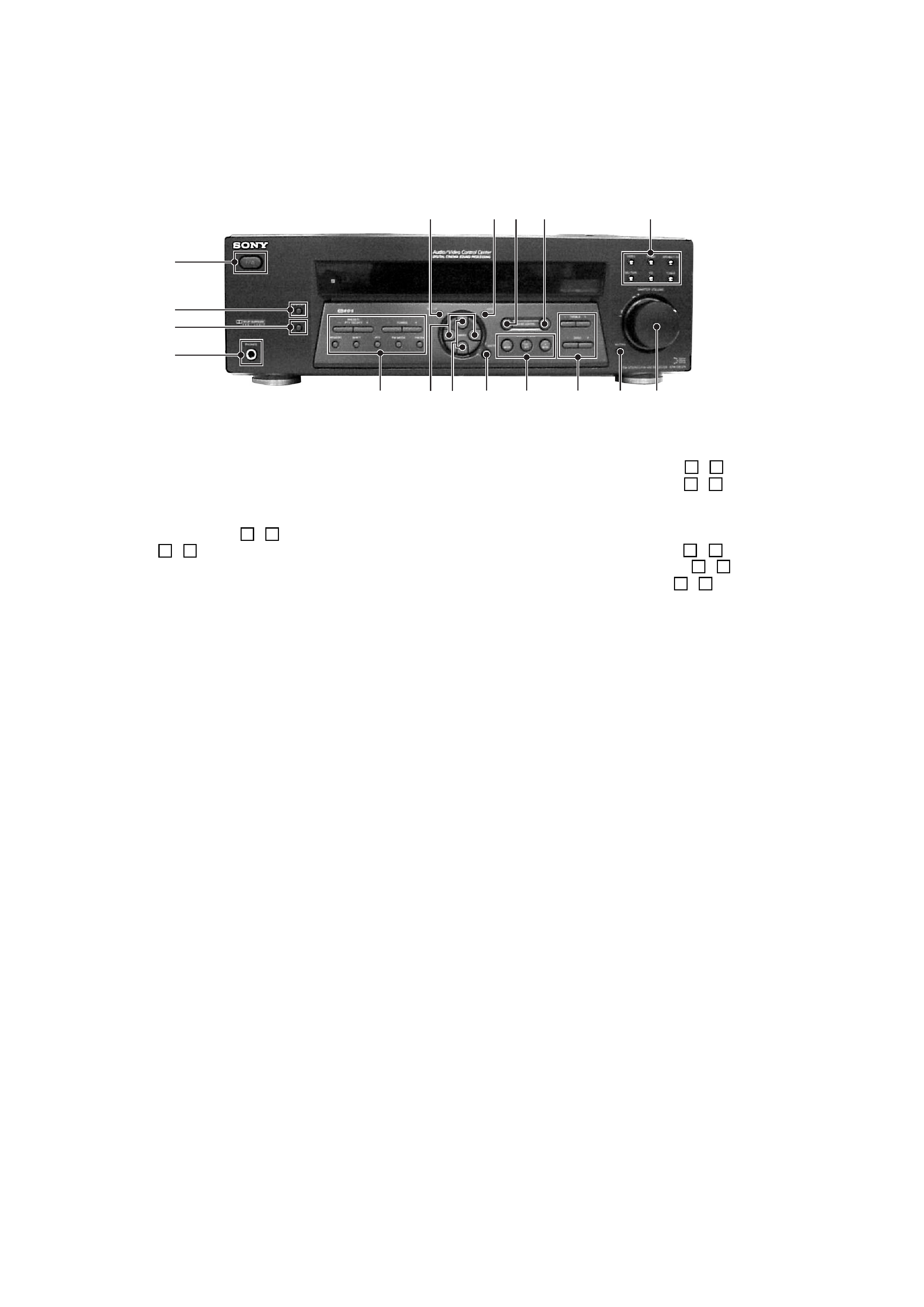
Front Panel
1
2
3
4
5qs
qa
qf
qd
q;
7 8
6
9
qg
qh
qj
1
?/1
(POWER) button
2
DISPLAY button
3
DIMMER button
4
PHONES jack
5
PRESET/PTY SELECT + , buttons
TUNING + , buttons
MEMORY button
SHIFT button
PTY button
FM MODE button
FM/AM button
6
SET UP button and indicator
7
NAME button and indicator
8
LEVEL button and indicator
9
SUR button and indicator
q;
VIDEO button
TV/SAT button
DVD/MULTI CH button
MD/TAPE button
CD button
TUNER button
qa
MENU < , > buttons
qs
MENU + , buttons
qd
ENTER button
qf
SOUND FIELD ON/OFF
(and indicator),
MODE + , buttons
qg
TREBLE + , buttons
BASS + , buttons
qh
MUTING button
qj
MASTER VOLUME control
5
STR-DE375
This section is extracted
from instruction manual.
qs
qa
3 45 6 7
9
q;
1
2
8
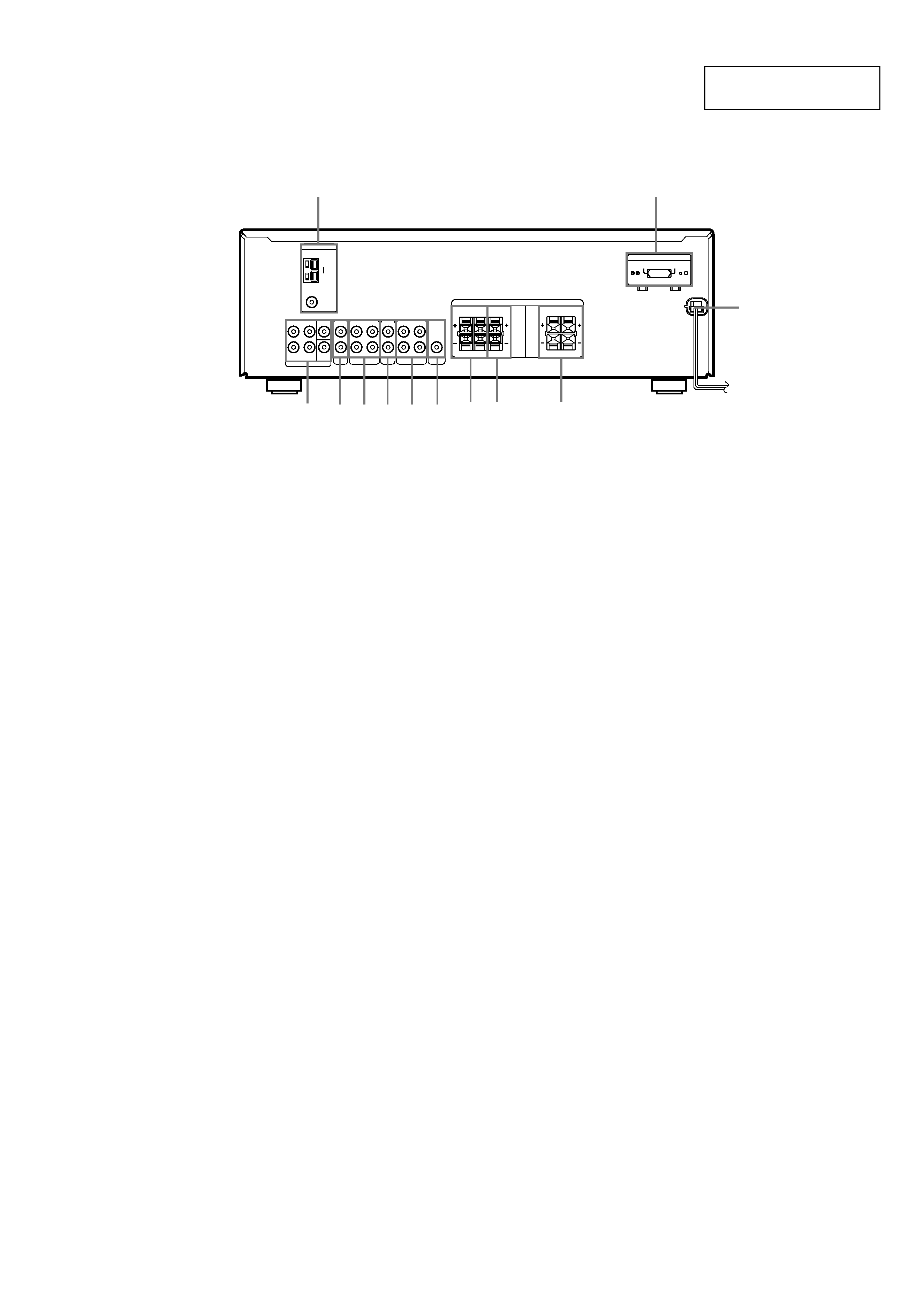
1
ANTENNA (AM/FM)
2
DVD/MULTI CH
3
CD
4
MD/TAPE
5
TV/SAT
6
VIDEO
7
SUB WOOFER
8
SPEAKERS SURROUND
9
SPEAKERS CENTER
q;
SPEAKERS FRONT
qa
VOLTAGE SELECTOR
(except Singapore, Malaysia and
Canada models)
qs
AC power cord
Rear Panel