2
US
Getting Started
WARNING
To prevent fire or shock
hazard, do not expose
the unit to rain or
moisture.
To avoid electrical shock, do not open
the cabinet. Refer servicing to qualified
personnel only.
Do not install the appliance in a
confined space, such as a bookcase or
built-in cabinet.
For the customers in Canada
CAUTION
TO PREVENT ELECTRIC SHOCK, DO
NOT USE THIS POLARIZED AC PLUG
WITH AN EXTENSION CORD,
RECEPTACLE OR OTHER OUTLET
UNLESS THE BLADES CAN BE FULLY
INSERTED TO PREVENT BLADE
EXPOSURE.
ENERGY STAR® is a U.S.
registered mark.
As an ENERGY STAR®
partner, Sony
Corporation has
determined that this
product meets the
ENERGY STAR® guidelines
for energy efficiency.
Precautions
On safety
· Should any solid object or liquid fall
into the cabinet, unplug the receiver
and have it checked by qualified
personnel before operating it any
further.
On power sources
· Before operating the receiver, check
that the operating voltage is identical
with your local power supply. The
operating voltage is indicated on the
nameplate at the rear of the receiver.
· The receiver is not disconnected from
the AC power source (MAINS) as
long as it is connected to the wall
outlet, even if the receiver itself has
been turned off.
· If you are not going to use the
receiver for a long time, be sure to
disconnect the receiver from the wall
outlet. To disconnect the AC power
cord, grasp the plug itself; never pull
the cord.
· Should the AC power cord need to be
changed, have it done at a qualified
service shop only.
On placement
· Place the receiver in a location with
adequate ventilation to prevent heat
build-up and prolong the life of the
receiver.
· Do not place the receiver near heat
sources, or in a place subject to direct
sunlight, excessive dust or
mechanical shock.
· Do not place anything on top of the
cabinet that might block the
ventilation holes and cause
malfunctions.
On operation
· Before connecting other components,
be sure to turn off and unplug the
receiver.
On cleaning
· Clean the cabinet, panel and controls
with a soft cloth slightly moistened
with a mild detergent solution. Do
not use any type of abrasive pad,
scouring powder or solvent such as
alcohol or benzine.
If you have any question or problem
concerning your receiver, please
consult your nearest Sony dealer.
3
US
Getting Started
TABLE OF CONTENTS
Getting Started
Unpacking 4
Hookup Overview 4
Antenna Hookups 5
Audio Component Hookups 5
Video Component Hookups 6
Speaker System Hookups 7
AC Hookups 9
Before You Use Your Receiver 9
Receiver Operations
Selecting a Component 10
Receiving Broadcasts 12
Presetting Radio Stations 13
Recording 14
Using the Sleep Timer 14
Using Surround Sound
Choosing a Sound Field 15
Getting the Most Out of Dolby Pro Logic Surround Sound 16
Additional Information
Troubleshooting 19
Specifications 20
Glossary 22
Index 23
Rear Panel Descriptions 24
Remote Button Descriptions 25
Quick Reference Guide 26
About This Manual
The instructions in this manual are for
models STR-DE345 and STR-DE245.
Check your model number by looking
at the upper right corner of the front
panel or lower right corner of the
remote. In this manual, the STR-DE345
and the remote RM-U304 are used for
illustration purposes. Any difference in
operation is clearly indicated in the text,
for example, "STR-DE345 only".
Type of differences
Conventions
· The instructions in this manual
describe the controls on the receiver.
You can also use the controls on the
remote if they have the same or
similar names as those on the
receiver. For details on the use of the
remote RM-PP404 (STR-DE345 only),
refer to the separate operating
instructions supplied with the
remote.
· A "Quick Reference Guide" is
supplied on page 26.
· The "Remote Button Descriptions"
section on page 25 provides an
overview of the remote buttons for
RM-U304.
· The following icons are used in this
manual:
Indicates that you can use only the
remote to do the task.
Indicates hints and tips for making
the task easier.
This receiver contains a Dolby Pro Logic
Surround decoder.
Manufactured under license from Dolby
Laboratories.
"Dolby", "Pro Logic" and the double-D
symbol ; are trademarks of Dolby
Laboratories.
US
5.1 CH (VIDEO IN)
VIDEO
MONITOR
Feature
DE345
·
·
Model
DE245
4
US
Getting Started
Unpacking
Check that you received the following items with the
receiver:
· FM wire antenna (1)
· AM loop antenna (1)
· Remote commander (remote) (1)
Model
Remote
STR-DE345
RM-PP404
STR-DE245
RM-U304
· Size AA (R6) batteries (2)
· Operating instructions of the remote RM-PP404
(STR-DE345 only)
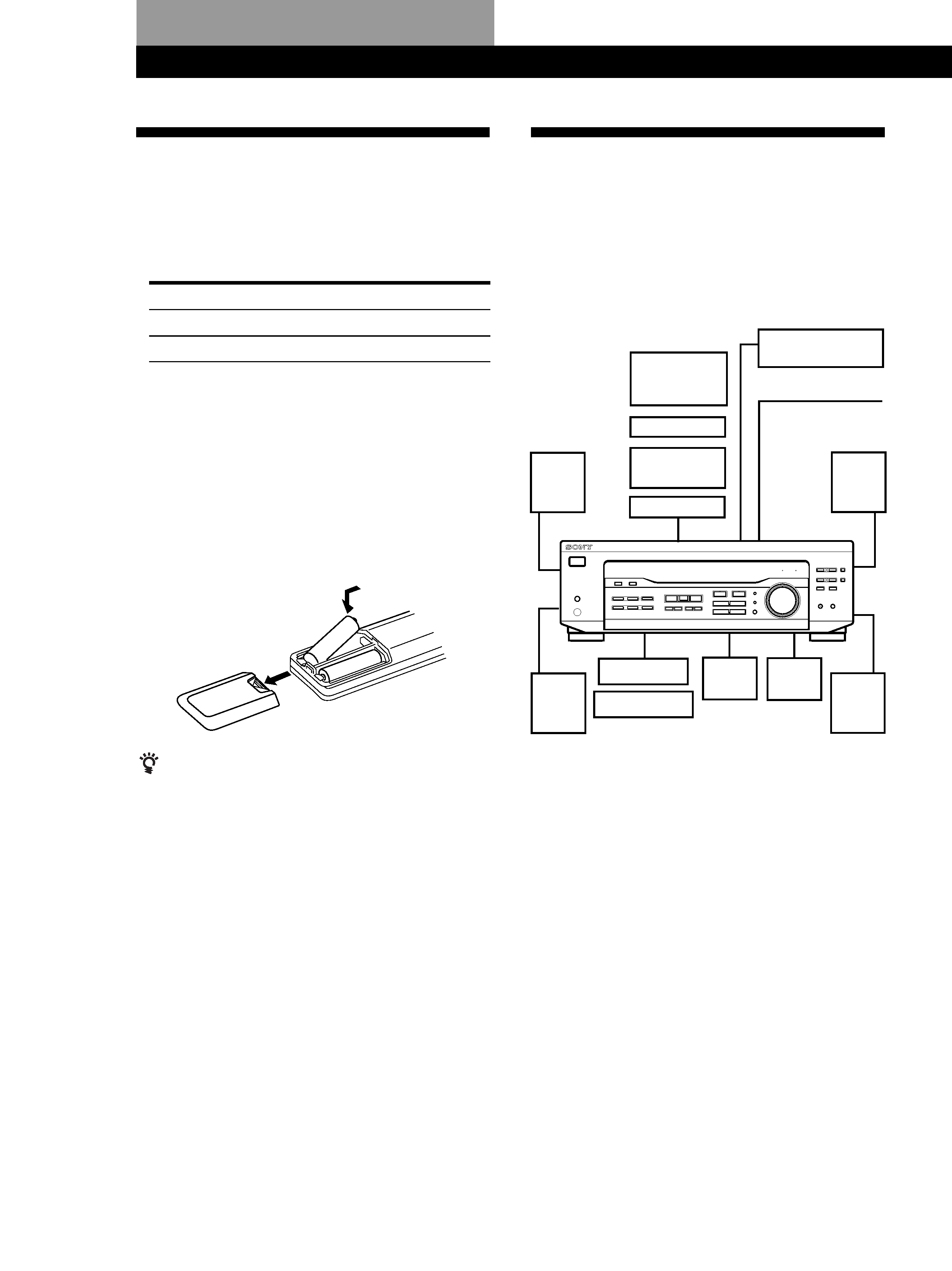
Inserting batteries into the remote
Insert two size AA (R6) batteries in accordance with
the + and markings on the battery compartment.
When using the remote, point it at the remote sensor g
on the receiver.
When to replace batteries
Under normal use, the batteries should last for about 6
months. When the remote no longer operates the
receiver, replace both batteries with new ones.
Notes
· Do not leave the remote in an extremely hot or humid
place.
· Do not use a new battery with an old one.
· Do not expose the remote sensor to direct sunlight or
lighting apparatuses. Doing so may cause a malfunction.
· If you don't use the remote for an extended period of time,
remove the batteries to avoid possible damage from
battery leakage and corrosion.
Hookup Overview
The receiver allows you to connect and control the
following audio/video components. Follow the
hookup procedures for the components that you want
to connect to the receiver on the pages specified. To
learn the locations and names of each jack, see "Rear
Panel Descriptions" on page 24.
Before you get started
· Turn off the power to all components before making
any connections.
· Do not connect the AC power cords until all of the
connections are completed.
· Be sure to make connections firmly to avoid hum
and noise.
· When connecting an audio/video cable, be sure to
match the color-coded pins to the appropriate jacks
on the components: Yellow (video) to Yellow; White
(left, audio) to White; and Red (right, audio) to Red.
]
]
}
}
AM/FM antenna
DVD player/Dolby
Digital decoder
Front
speaker
(L)
Speaker
System
Hookups (7)
Antenna Hookups (5)
Front
speaker
(R)
Rear
speaker
(L)
Rear
speaker
(R)
CD player
MD/Tape deck
Center
speaker
Active
woofer
Video Component
Hookups (6)
Audio Component
Hookups (5)
TV monitor
(STR-DE345
only)
TV tuner
SAT (Satellite
receiver)
VCR
Getting Started
5
US
Getting Started
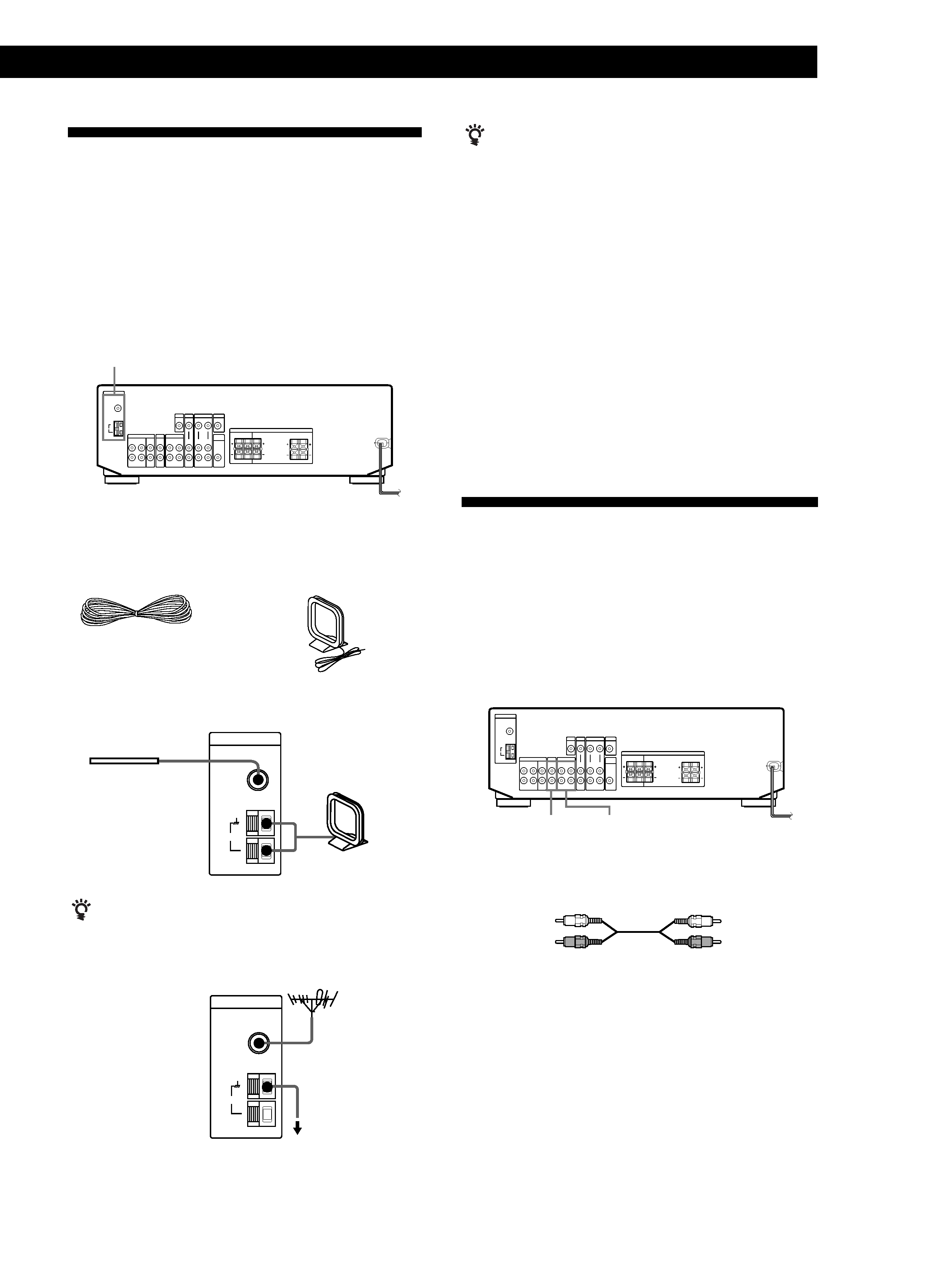
Antenna Hookups
Overview
This section describes how to connect AM and FM
antennas to the receiver. If you want to receive radio
broadcasts with the receiver, complete these
connections first, then go to the following pages.
For specific locations of the terminals, see the
illustration below.
What antennas will I need?
If you have poor AM reception
Connect a 20 to 50 ft. (6 to 15-meter) insulated wire (not
supplied) to the AM antenna terminal in addition to the
AM loop antenna. Try to extend the wire outdoors and
keep it horizontal.
Connecting a ground wire
If you connect the receiver to an outdoor antenna,
ground it against lightning as shown in the illustration
in the left column. To prevent a gas explosion, do not
connect the ground wire to a gas pipe.
Where do I go next?
If you want to connect other components, go on to the next
section. If you're only planning to use the receiver to listen to
the radio, go to "Speaker System Hookups" on pages 7 and 8.
Audio Component Hookups
Overview
This section describes how to connect your audio
components to the receiver. If you want to use the
receiver as an amplifier, complete these connections.
For specific locations of the jacks, see the illustration
below.
What cables will I need?
Audio cables (not supplied) (1 for CD player; 2 for each MD
recorder or tape deck)
· AM loop antenna
(supplied) (1)
· FM wire antenna
(supplied) (1)
Hookups
If you have poor FM reception
Use a 75-ohm coaxial cable (not supplied) to connect the
receiver to an outdoor FM antenna as shown below.
FM wire antenna
After connecting
the wire antenna,
keep it as
horizontal as
possible.
AM loop antenna
Receiver
(continued)
Receiver FM outdoor antenna
Ground wire
(not supplied)
to ground
ANTENNA
ANTENNA
AM
FM
75
COAXIAL
ANTENNA
AM
FM
75
COAXIAL
MD/TAPE
CD
Red (R)
Red (R)
White (L)
White (L)