1
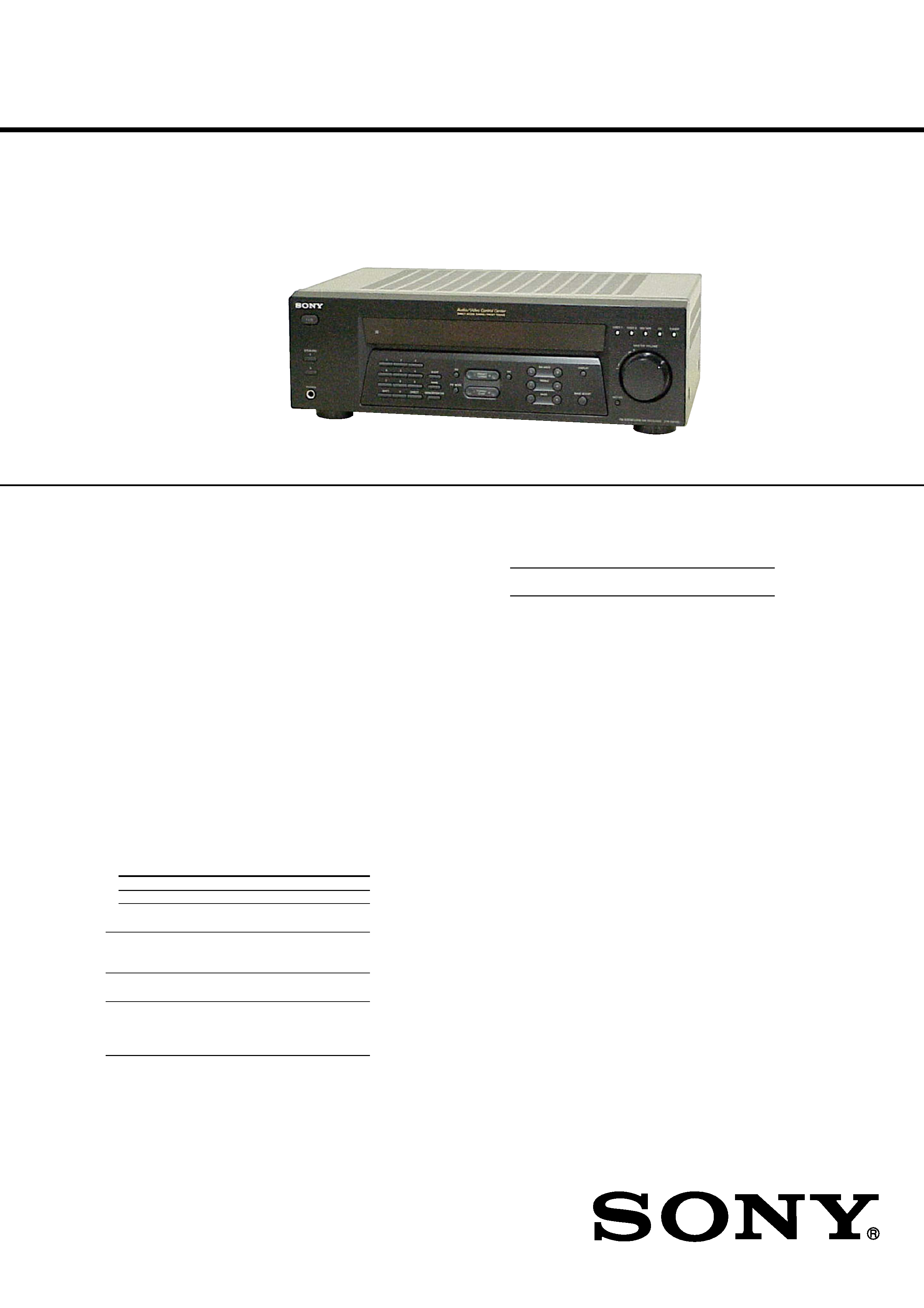
SERVICE MANUAL
US Model
AEP Model
UK Model
STR-DE185
FM STEREO/FM-AM RECEIVER
AUDIO POWER SPECIFICATIONS
POWER OUTPUT AND TOTAL
HARMONIC DISTORTION:
With 8 ohm loads, both channels driven, from
40 20,000 Hz; rated 100 watts per channel
minimum RMS power, with no more than
0.09 % total harmonic distortion from 250
milliwatts to rated output (Models of area code
US only).
Amplifier section
POWER OUTPUT
Models of area code US
Rated Power Output at Stereo Mode
(8 ohms 40 Hz 20 kHz, THD 0.09 %)
100 W + 100 W
Models of area code AEP, UK
Rated Power Output at Stereo Mode
(
8 ohms 1 kHz, THD 0.7 %)
100 W + 100 W 1)
1) Measured under the following conditions:
Area code
Power requirements
AEP, UK
230 V AC, 50 Hz
Frequency response
CD, MD/TAPE,
20 Hz 50 kHz
VIDEO 1, VIDEO 2
+0/0.5 dB (with bass
boost bypassed)
Inputs (Analog)
CD, MD/TAPE,
Sensitivity: 250 mV
VIDEO 1, VIDEO 2
Impedance: 50 kilohms
S/N 2) : 85 dB
(A, 250 mV 3) )
2) INPUT SHORT.
3) Weighted network, input level.
SPECIFICATIONS
Outputs
MD/TAPE, VIDEO 1
Voltage: 250 mV
Impedance: 10 kilohms
Bass Boost:
+8 dB at 70 Hz
Tone:
±10 dB at 100 Hz and
10 kHz
FM tuner section
Tuning range
87.5 108.0 MHz
Antenna terminals
75 ohms, unbalanced
Intermediate frequency
10.7 MHz
Sensitivity
Mono:
18.3 dBf, 2.2 µV/75 ohms
Stereo:
38.3 dBf, 22.5 µV/75 ohms
Usable sensitivity
11.2 dBf, 1 µV/75 ohms
S/N
Mono:
76 dB
Stereo:
70 dB
Harmonic distortion at 1 kHz
Mono:
0.5%
Stereo:
0.8%
Separation
35 dB at 1 kHz
Frequency response
30 Hz 15 kHz,
+0.5/2 dB
Selectivity
60 dB at 400 kHz
Ver 1.1 2003. 11
9-873-586-02
2003K04-1
© 2003.11
Sony Corporation
Home Audio Company
Published by Sony Engineering Corporation
Continued on next page
2
SAFETY-RELATED COMPONENT WARNING!!
COMPONENTS IDENTIFIED BY MARK 0 OR DOTTED LINE
WITH MARK 0 ON THE SCHEMATIC DIAGRAMS AND IN
THE PARTS LIST ARE CRITICAL TO SAFE OPERATION.
REPLACE THESE COMPONENTS WITH SONY PARTS WHOSE
PART NUMBERS APPEAR AS SHOWN IN THIS MANUAL OR
IN SUPPLEMENTS PUBLISHED BY SONY.
STR-DE185
AM tuner section
Tuning range
Models of area code US
With 10-kHz tuning scale: 530 1710 kHz 4)
With 9-kHz tuning scale: 531 1710 kHz 4)
Models of area code AEP, UK
With 9-kHz tuning scale: 531 1602 kHz
Antenna
Loop antenna
Intermediate frequency
450 kHz
Usable sensitivity
50 dB/m (at 1,000 kHz or
999 kHz)
S/N
45 dB (at 50 mV/m)
Harmonic distortion
1.0 % (50 mV/m,
400 Hz)
Selectivity
At 9 kHz:
35 dB
At 10 kHz:
40 dB
4) You can change the AM tuning scale to 9 kHz or
10 kHz. After tuning in any AM station, turn off
the receiver. Hold down PRESET TUNING + and
press ?/1. All preset stations will be erased when
you change the tuning scale. To reset the scale to
10 kHz (or 9 kHz), repeat the procedure.
General
Power requirements
Area code
Power consumption
US
120 V AC, 60 Hz
AEP, UK
230 V AC, 50/60 Hz
Power consumption
Area code
Power consumption
US
190 W
AEP, UK
210 W
Power consumption (during standby mode)
0.5 W (for models of all area code)
AC outlets
Area code
AC outlets
US
1 switched, 120 W/1A MAX
AEP, UK
1 switched, 100 W MAX
Dimensions
430
× 145 × 300 mm
(16 7/8
× 5 6/8 × 11 6/8 in.)
including projecting parts
and controls
Mass (Approx.)
7.0 kg (15 lb 7 oz)
Supplied accessories
FM wire antenna (1)
AM loop antenna (1)
Remote commander RM-U185 (1)
R6 (size-AA) batteries (2)
Design and specifications are subject to change without
notice.
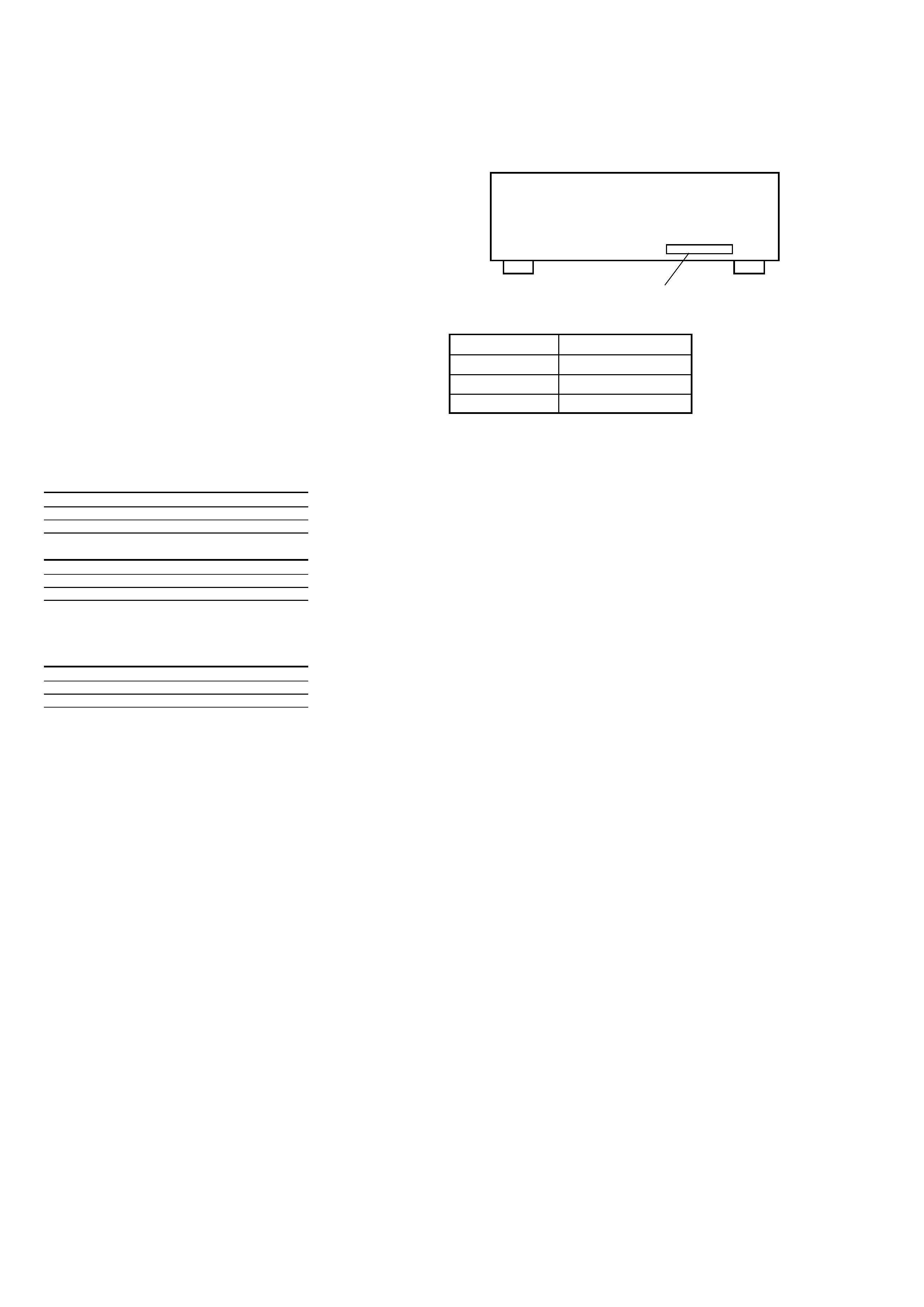
MODEL IDENTIFICATION
-- BACK PANEL --
Part No.
MODEL
PART No.
US
4-238-277-0s
AEP
4-238-277-1s
UK
4-238-277-2s
3
TABLE OF CONTENTS
1. GENERAL
Main unit ................................................................................. 4
Remote button description ....................................................... 5
2. DISASSEMBLY
2-1. Case ..................................................................................... 6
2-2. Front Panel Section ............................................................. 7
2-3. Back Panel ........................................................................... 7
2-4. Main Board ......................................................................... 8
3. TEST MODE ........................................................................ 9
4. DIAGRAMS
4-1. IC Pin Description ............................................................. 10
4-2. Circuit Boards Location .................................................... 11
4-3. Block Diagram Main Section ...................................... 12
4-4. Block Diagram Power Section .................................... 13
4-5. Printed Wiring Board Main Section ............................ 14
4-6. Printed Wiring Boards H/P, Outlet Section ................. 15
4-7. Schematic Diagram Main Section (1/2) ...................... 16
4-8. Schematic Diagram Main Section (2/2) ...................... 17
4-9. Schematic Diagram Display Section ........................... 18
4-10. Printed Wiring Board Display Section ........................ 19
4-11. Printed Wiring Board Power SW Section ................... 20
5. EXPLODED VIEWS
5-1. Case Section ...................................................................... 21
5-2. Front Panel Section ........................................................... 22
5-3. Chassis Section ................................................................. 23
6. ELECTRICAL PARTS LIST ......................................... 24
STR-DE185
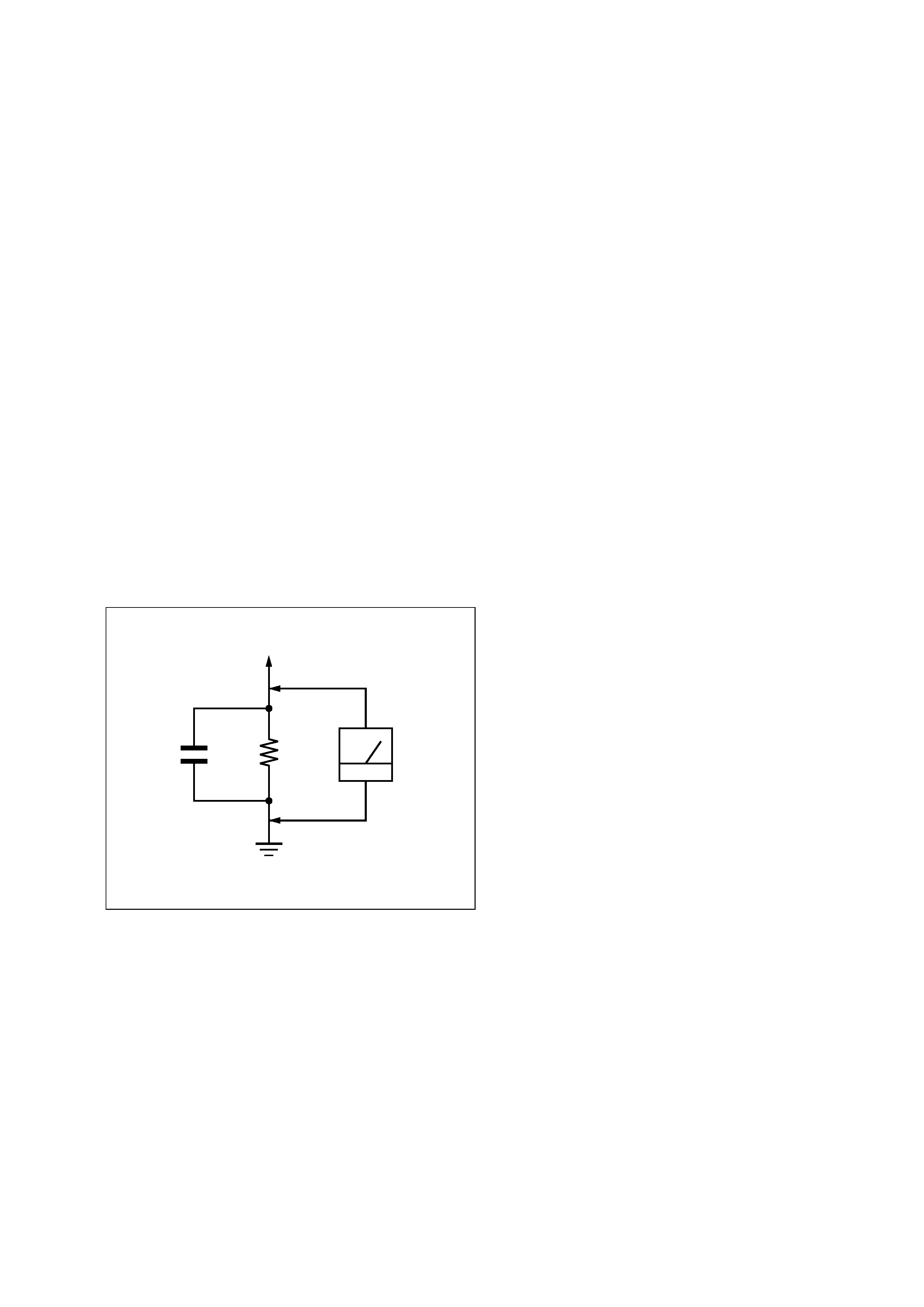
1.5 k
0.15
µF
AC
voltmeter
(0.75 V)
To Exposed Metal
Parts on Set
Earth Ground
Fig. A. Using an AC voltmeter to check AC leakage.
SAFETY CHECK-OUT
After correcting the original service problem, perform the following
safety check before releasing the set to the customer:
Check the antenna terminals, metal trim, "metallized" knobs, screws,
and all other exposed metal parts for AC leakage. Check leakage as
described below.
LEAKAGE TEST
The AC leakage from any exposed metal part to earth ground and
from all exposed metal parts to any exposed metal part having a
return to chassis, must not exceed 0.5 mA (500 microamperes).
Leakage current can be measured by any one of three methods.
1. A commercial leakage tester, such as the Simpson 229 or RCA
WT-540A. Follow the manufacturers' instructions to use these
instruments.
2. A battery-operated AC milliammeter. The Data Precision 245
digital multimeter is suitable for this job.
3. Measuring the voltage drop across a resistor by means of a VOM
or battery-operated AC voltmeter. The "limit" indication is 0.75
V, so analog meters must have an accurate low-voltage scale. The
Simpson 250 and Sanwa SH-63Trd are examples of a passive
VOM that is suitable. Nearly all battery operated digital
multimeters that have a 2V AC range are suitable. (See Fig. A)
4
STR-DE185
SECTION 1
GENERAL
This section is extracted
from instruction manual.
List
of
Button
Locations
and
Reference
Pages
5GB
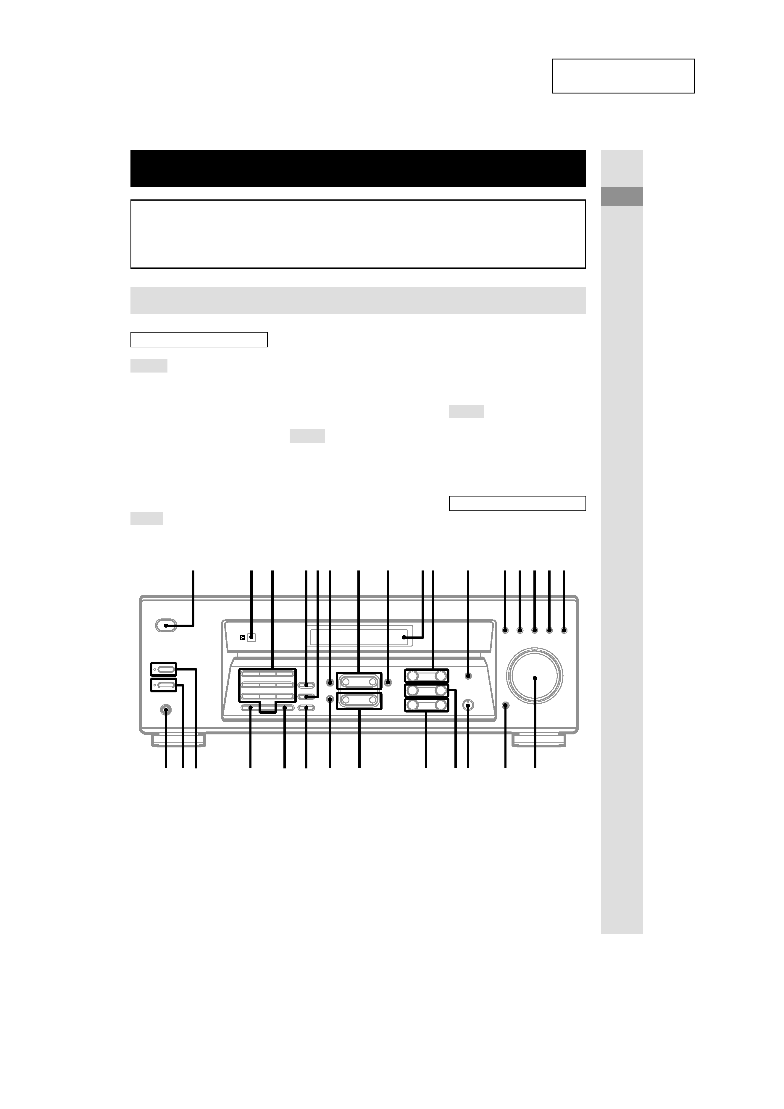
List of Button Locations and Reference Pages
Main unit
How to use this page
Use this page to find the location of buttons that are
mentioned in the text.
Illustration number
r
NAME 5 (18)
RR
Name of button/part
Reference page
ALPHABETICAL ORDER
A H
AM 8 (13, 14)
BALANCE L/R q; (12)
BASS +/ wa (12)
BASS BOOST ql (12)
CD qg (8, 12)
DIRECT wg (13)
DISPLAY qa (12, 16)
Display 9 (11-16, 18, 19)
FM 6 (13, 14)
FM MODE wd (14)
I O
IR (receptor) 2 (4, 22)
SHIFT wh (15)
SLEEP (models of area code U)
4
(19)
SPEAKERS A wj (10, 12)
SPEAKERS B wk (10, 12)
T Z
TREBLE +/ w; (12)
TUNER qh (8, 12-15, 18)
TUNING/CHAR +/ ws (14, 18)
VIDEO 1 qs (12)
VIDEO 2 qd (8, 12)
BUTTON DESCRIPTIONS
?/1
(power) 1 (11, 13, 23)
MASTER VOLUME qj (12, 20)
MD/TAPE qf (8, 12)
MEMORY/ENTER wf (13, 15,
18)
MUTING qk (12, 20)
NAME 5 (18)
Numeric buttons 3 (13)
P S
PHONES wl (12, 21)
PRESET/PTY SELECT +/
(models of area code CEL,
CEK) 7 (15, 16)
PRESET TUNING +/ (models of
area code U) 7 (15, 23)
PTY (models of area code CEL,
CEK) 4 (16)
1
2
3
456
7
8
9q;
qa
qs qd qf qg qh
qj
qk
ql
w;
wa
ws
wd
wf
wg
wh
wj
wk
wl
5
STR-DE185
24GB
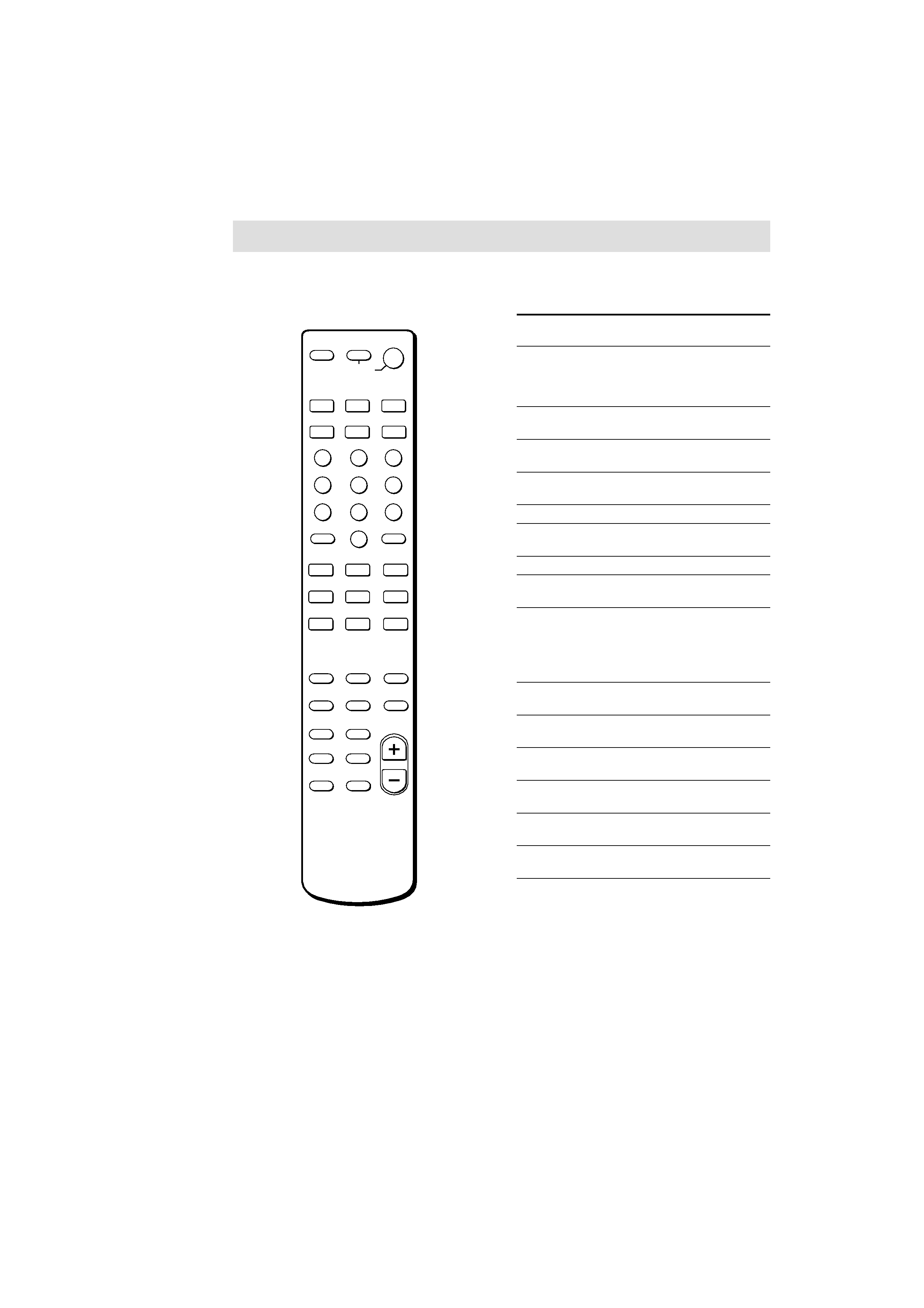
Remote button description
You can use the remote RM-U185 to operate
the components in your system.
>10
0
78
9
45
6
12
3
ENTER
CD
VIDEO 2
MD/TAPE
VIDEO 1
DVD
·
TUNER
SYSTEM
STANDBY
SHIFT
CH/PRESET +
TREBLE
MUTING
BASS BOOST
TV/VIDEO
/
ANT
TV/VTR
+
BASS
+
TV VOL
TV CH
+
+
L BALANCE R
MASTER
VOL
RETURN
D. TUNING
TOP MENU
DVD MENU
ENTER
f
F
G
g
SLEEP
AV
?/1
?/1
D.SKIP
The tables below show the settings of each
button.
Remote
Operations
Function
Button
SLEEP
Receiver
Activates the sleep
function and the duration
which the receiver turns
off automatically.
?/1
Receiver
Turns the receiver on or
off.
VIDEO 1
Receiver
To watch VCR.
(VTR mode 3)
VIDEO 2
Receiver
To watch VCR.
(VTR mode 1)
DVD
Receiver
To watch DVD.
MD/TAPE
Receiver
To listen to Minidisc or
audio tape.
CD
Receiver
To listen to compact disc.
TUNER
Receiver
To listen to radio
programs.
SHIFT
Receiver
Press repeatedly to select
a memory page for
presetting radio stations
or tuning to preset
stations.
D.TUNING Receiver
Tuner station direct
key-in-mode.
BALANCE Receiver
Adjust the balance.
L/R
BASS
Receiver
Reinforce the bass.
BOOST
TREBLE
Receiver
Adjust the treble tone
+/
quality.
MUTING Receiver
Mutes the sound from the
receiver.
BASS +/ Receiver
Adjust the bass tone
quality.
Note
When you press the function buttons (VIDEO 1,
VIDEO 2, DVD), the input mode of the TV might not
switch to the corresponding input mode that you
want. In this case, press the TV/VIDEO button to
switch the input mode of the TV.
X
x
N
m
M
.
>
O