STR-DA777ES/V777ES
US Model
Canadian Model
E Model
Australian Model
PX Model
STR-DA777ES
Chinese Model
STR-V777ES
SERVICE MANUAL
FM STEREO FM-AM RECEIVER
MICROFILM
-- Continued on next page --
SPECIFICATIONS
Manufactured under license from Dolby Laboratories
Licensing Corporation.
Dolby, "DOLBY", the double-D symbol ;, AC-3 and
"Pro Logic" are trademarks of Dolby Laboratories
Licensing Corporation.
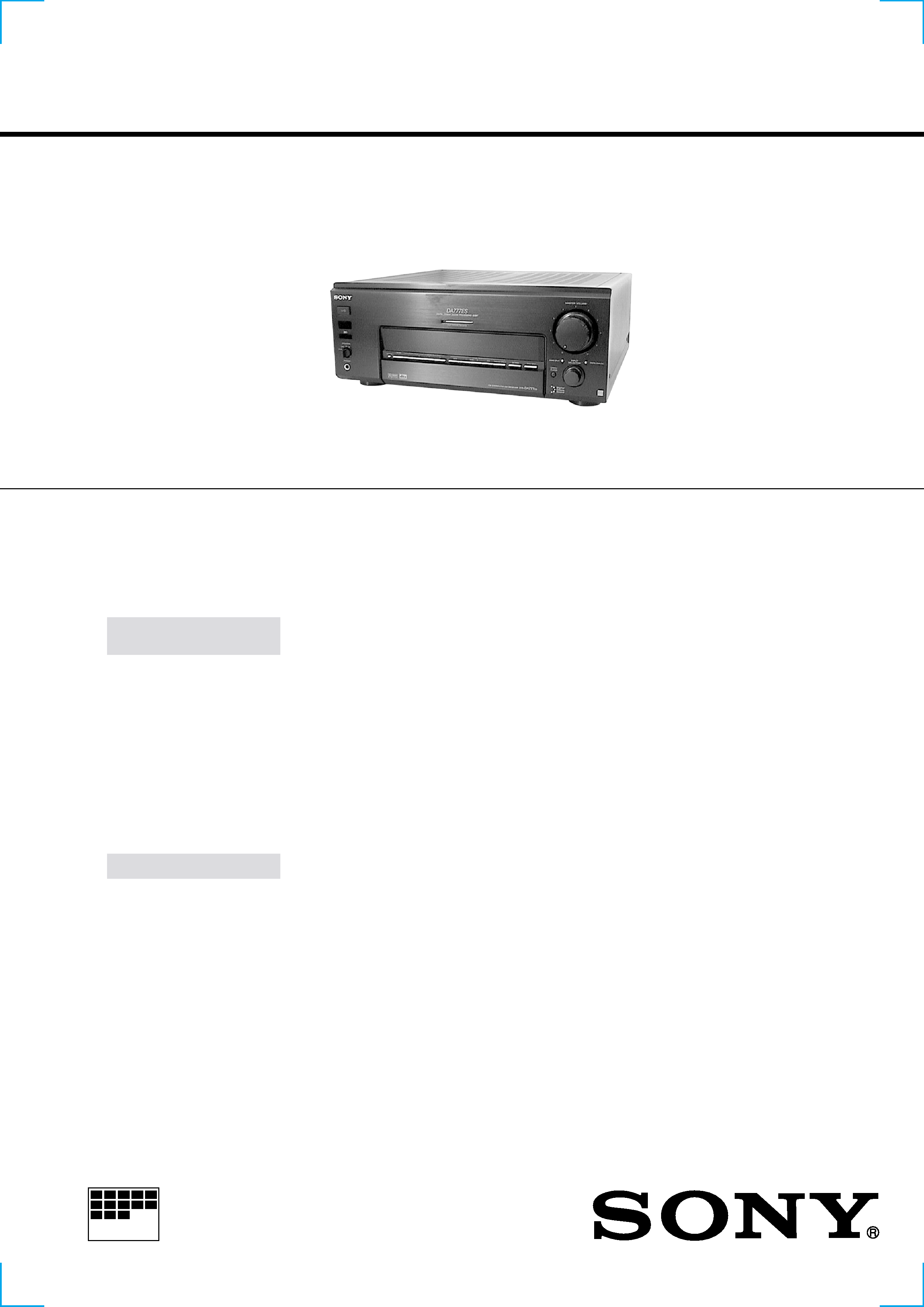
Photo : STR-DA777ES
AUDIO POWER
SPECIFICATIONS
POWER OUTPUT AND
TOTAL HARMONIC
DISTORTION:
With 8
loads, both
channels driven, from 20 -
20,000 Hz; rated 120 watts
per channel minimum RMS
power, with no more than
0.05% total harmonic
distortion from 250
milliwatts to rated output.
(US model only)
Audio section
POWER OUTPUT
Stereo mode
8
120 W + 120 W
4
100 W + 100 W
(THD 0.05%,
20 Hz - 20 kHz)*
(DIN 1 kHz)
Surround mode
8
Front: 120W + 120W
Centera): 120W
Reara):
120W + 120W
4
Front: 100W + 100W
Centera): 100W
Reara):
100W + 100W
(THD 0.05%,
20 Hz - 20 kHz)*
(DIN 1 kHz)
* US/Canadian models only .
a) Depending on the sound field settings and
the source, there may be no sound output.
Frequency response
PHONO:
20 Hz ~ 20 kHz
RIAA
±0.5 dB
LINE (TUNER, CD,
MD/DAT, TAPE,
TV/SAT or TV/LD,
DVD/LD or DVD,
VIDEO 1, 2, and
VIDEO 3):
10 Hz ~ 100 kHz
+0.5/2.0 dB
(ANALOG DIRECT)
Signal-to-noise ratio
DIGITAL: 100 dB
(A, 20 kHz LPF)
PHONO: 86 dB**
(A, 5 mV)
LINE: 100 dB**
(A, 20 kHz LPF)
** ANALOG DIRECT
Inputs (Analog)
PHONO:
Sensitivity: 4 mV
Impedance:
50 k
LINE (TUNER, CD,
MD/DAT, TAPE,
TV/SAT or TV/LD,
DVD/LD or DVD,
VIDEO 1, 2, and
VIDEO 3):
Sensitivity: 200 mV
Impedance:
50 k
Inputs (Digital)
Coaxial (DVD/LD or
DVD, CD) :
Sensitivity:
Impedance: 75
Optical (DVD/LD or
DVD, TV/SAT or
TV/LD, MD/DAT) :
Sensitivity:
Impedance:
Outputs (Analog)
REC OUT
(MD/DAT, TAPE,
VIDEO 1, 2, 3):
Voltage: 200 mV,
Impedance:
1 k
PRE OUT
(FRONT L/R,
CENTER,
REAR L/R,
SUB WOOFER):
Voltage: 2 V
Impedance:
1 k
PHONES:
Accepts low- and
high-impedance
headphones
2
MODEL
DA777ES: US model
DA777ES: Canadian model
DA777ES: E, PX models
DA777ES:
Malaysia, Singapore,
Australian models
V777ES:
Chinese model
PARTS No.
4-222-054-0s
4-222-054-1s
4-222-054-2s
4-222-054-3s
4-222-054-4s
PART NO.
MODEL IDENTIFICATION
BACK PANEL
FM tuner section
Tuning range
87.5 - 108.0 MHz
Antenna terminals
75
, unbalanced
Sensitivity
Mono: 18.3 dBf,
2.2
µV/75
Stereo: 38.3 dBf,
22.5
µV/75
Usable sensitivity
11.2 dBf, 1
µV/75
S/N
Mono: 76 dB
Stereo: 70 dB
Harmonic distortion at 1 kHz
Mono: 0.3%
Stereo: 0.5%
Separation
45 dB at 1 kHz
Frequency response
30 Hz - 15 kHz
+0.5/2 dB
Selectivity
60 dB at 400 kHz
AM tuner section
Tuning range
US/Canadian models:
With 10-kHz tuning
scale:
530 - 1710 kHz
With 9-kHz tuning
scale:
531 - 1710 kHz
Singapore/Malaysia
models:
5311602 kHz (9 kHz
interval)
Other models:
5311602 kHz
(9 kHz interval)
5301610 kHz
(10 kHz interval)
Antenna
Loop antenna
Usable sensitivity
50 dB/m (at 1,000 kHz
or 999 kHz)
S/N
54 dB (at 50 mV/m)
Harmonic distortion
0.5 % (50 mV/m,
400 kHz)
Selectivity
At 9 kHz: 35 dB
At 10 kHz: 40 dB
Video section
Inputs
Video: 1 Vp-p 75
S-video:
Y: 1 Vp-p 75
C: 0.286 Vp-p
75
Outputs
Video: 1 Vp-p 75
S-video:
Y: 1 Vp-p 75
C: 0.286 Vp-p
75
General
Power requirements
US/Canadian models:
120 V AC, 60Hz
Singapore/Malaysia
models:
220 - 230 V AC,
50/60 Hz
Other models:
120/220/240 V AC,
50/60 Hz
Power consumption
US model: 450 W
Canadian model:
650 VA
Singapore/Malaysia
models: 420 W
Other models: 450 W
AC outlets
US/Canadian models:
2 switched,
total 120 W/1 A
Other models:
2 switched,
total 100 W
Dimensions
430
× 174 × 462 mm
(17
× 6 7/8 ×
18 1/4 inches)
including projecting
parts and controls
Mass (Approx.)
24.5 kg (54 lbs. 1 oz.)
Supplied accessories
Design and specifications are subject.
to change without notice.
·
FM wire antenna (1)
·
AM loop antenna (1)
·
Remote commander
RM-TP503 (remote) (1)
·
LR6 (size-AA) alkaline
batteries (4)
·
Coin shaped lithium battery
(CR-2032) (1)
US/Canadian models only:
·
Audio/video/control S
connecting cord (1)
·
CONTROL S connecting
cord (1)
Outputs (Digital)
Optical (MD/DAT)
Sampling Frequency
48 kHz
EQ
BASS:
99 Hz ~ 1.0 kHz
(21 steps)
MID:
198 Hz ~ 10 kHz
(37 steps)
TREBLE:
1.0 kHz ~ 10 kHz
(23 steps)
Gain levels:
±10 dB, 0.5 dB step
Decodable Digital Fomats
Dolby Digital (AC-3),
DTS
3
SAFETY-RELATED COMPONENT WARNING!!
COMPONENTS IDENTIFIED BY MARK 0 OR DOTTED LINE WITH
MARK 0 ON THE SCHEMATIC DIAGRAMS AND IN THE PARTS
LIST ARE CRITICAL TO SAFE OPERATION. REPLACE THESE
COMPONENTS WITH SONY PARTS WHOSE PART NUMBERS
APPEAR AS SHOWN IN THIS MANUAL OR IN SUPPLEMENTS
PUBLISHED BY SONY.
After correcting the original service problem, perform the
following safety checks before releasing the set to the customer:
Check the antenna terminals, metal trim, "metallized" knobs, screws,
and all other exposed metal parts for AC leakage. Check leakage as
described below.
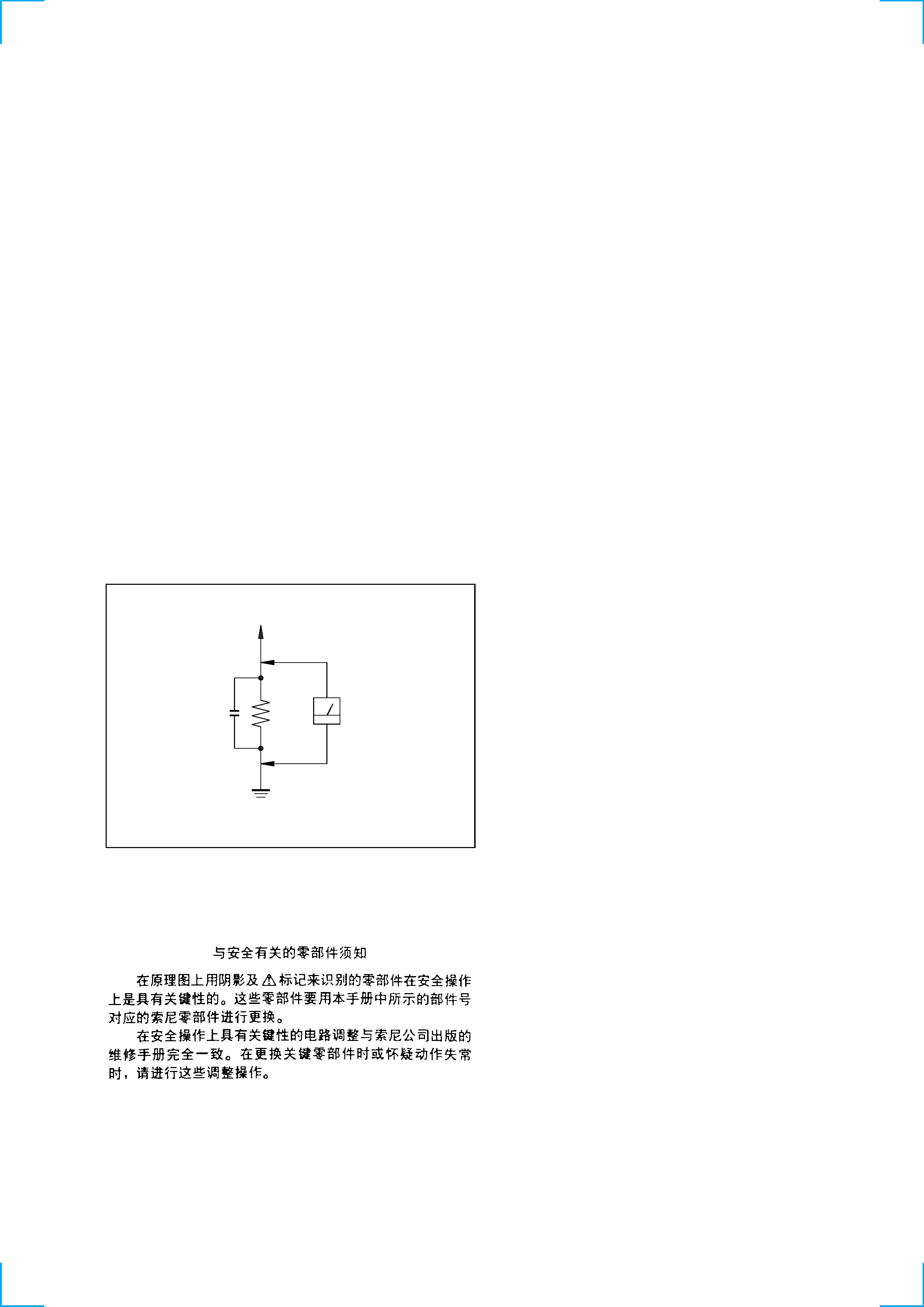
LEAKAGE
The AC leakage from any exposed metal part to earth ground
and from all exposed metal parts to any exposed metal part having
a return to chassis, must not exceed 0.5 mA (500 microamperes).
Leakage current can be measured by any one of three methods.
1.
A commercial leakage tester, such as the Simpson 229 or RCA
WT-540A. Follow the manufacturers' instructions to use these
instruments.
2.
A battery-operated AC milliammeter. The Data Precision 245
digital multimeter is suitable for this job.
3.
Measuring the voltage drop across a resistor by means of a
VOM or battery-operated AC voltmeter. The "limit" indication
is 0.75 V, so analog meters must have an accurate low-voltage
scale. The Simpson 250 and Sanwa SH-63Trd are examples of
a passive VOM that is suitable. Nearly all battery operated
digital multimeters that have a 2V AC range are suitable. (See
Fig. A)
SAFETY CHECK-OUT
To Exposed Metal
Parts on Set
0.15
µF
1.5 k
AC
Voltmeter
(0.75 V)
Earth Ground
Fig. A. Using an AC voltmeter to check AC leakage.
ATTENTION AU COMPOSANT AYANT RAPPORT
À LA SÉCURITÉ!
LES COMPOSANTS IDENTIFÉS PAR UNE MARQUE 0 SUR LES
DIAGRAMMES SCHÉMATIQUES ET LA LISTE DES PIÈCES SONT
CRITIQUES POUR LA SÉCURITÉ DE FONCTIONNEMENT. NE
REMPLACER CES COMPOSANTS QUE PAR DES PIÈSES SONY
DONT LES NUMÉROS SONT DONNÉS DANS CE MANUEL OU
DANS LES SUPPÉMENTS PUBLIÉS PAR SONY.
TABLE OF CONTENTS
1.
GENERAL ······································································ 4
2.
ADJUSTMENT ······························································ 6
3.
DIAGRAMS ···································································· 7
3-1.
Circuit Board Location ······················································· 7
3-2.
Block Diagram Main Section ············································· 8
3-3.
Block Diagram Digital Section ·········································· 9
3-4.
Block Diagram Control Section ······································· 10
3-5.
Block Diagram Power Section ········································· 11
3-6.
Printed Wiring Board Audio Section ································ 12
3-7.
Schematic Diagram Audio Section ··································· 13
3-8.
Printed Wiring Board Video Section ································ 14
3-9.
Schematic Diagram Video Section ··································· 15
3-10. Printed Wiring Board Volume Section(SIDE A) ·············· 16
3-11. Printed Wiring Board Volume Section(SIDE B) ············· 17
3-12. Schematic DiagramVolume Section(1/2) ························· 18
3-13. Schematic DiagramVolume Section(2/2) ························· 19
3-14. Printed Wiring Board Digital Section(SIDE A) ··············· 20
3-15. Printed Wiring Board Digital Section(SIDE B) ··············· 21
3-16. Schematic Diagram Digital Section(1/7) ························· 22
3-17. Schematic Diagram Digital Section(2/7) ························· 23
3-18. Schematic Diagram Digital Section(3/7) ························· 24
3-19. Schematic Diagram Digital Section(4/7) ························· 25
3-20. Schematic Diagram Digital Section(5/7) ························· 26
3-21. Schematic Diagram Digital Section(6/7) ························· 27
3-22. Schematic Diagram Digital Section(7/7) ························· 28
3-23. Printed Wiring Board AMP Section ································· 29
3-24. Schematic Diagram AMP Section(1/2) ···························· 30
3-25. Schematic Diagram AMP Section(2/2) ···························· 31
3-26. Printed Wiring Board Display Section(SIDE A) ·············· 32
3-27. Printed Wiring Board Display Section(SIDE B) ·············· 33
3-28. Schematic Diagram Display Section(1/2) ························ 34
3-29. Schematic Diagram Display Section(2/2) ························ 35
3-30. Printed Wiring Board Switch Section ······························ 36
3-31. Printed Wiring Board Control Jack Section ····················· 37
3-32. Schematic Diagram Control Jack Section ························ 37
3-33. Printed Wiring Board Speaker Terminal Section ············· 38
3-34. Schematic Diagram Speaker Terminal Section ················ 39
3-35. Printed Wiring Board Power Supply Section ··················· 40
3-36. Printed Wiring Board AC Power Supply Section ············· 41
3-37. Schematic Diagram Power Supply Section ······················ 42
3-38. IC Block Diagrams ··························································· 43
3-39. IC Pin Function Description ············································· 47
4.
EXPLODED VIEWS
4-1.
Case Section ····································································· 52
4-2.
Chassis Section ································································· 53
4-3.
Front Panel Section ·························································· 54
4-4.
Back Panel Section ··························································· 56
5.
ELECTRICAL PARTS LIST ··································· 57
4
SECTION 1
GENERAL
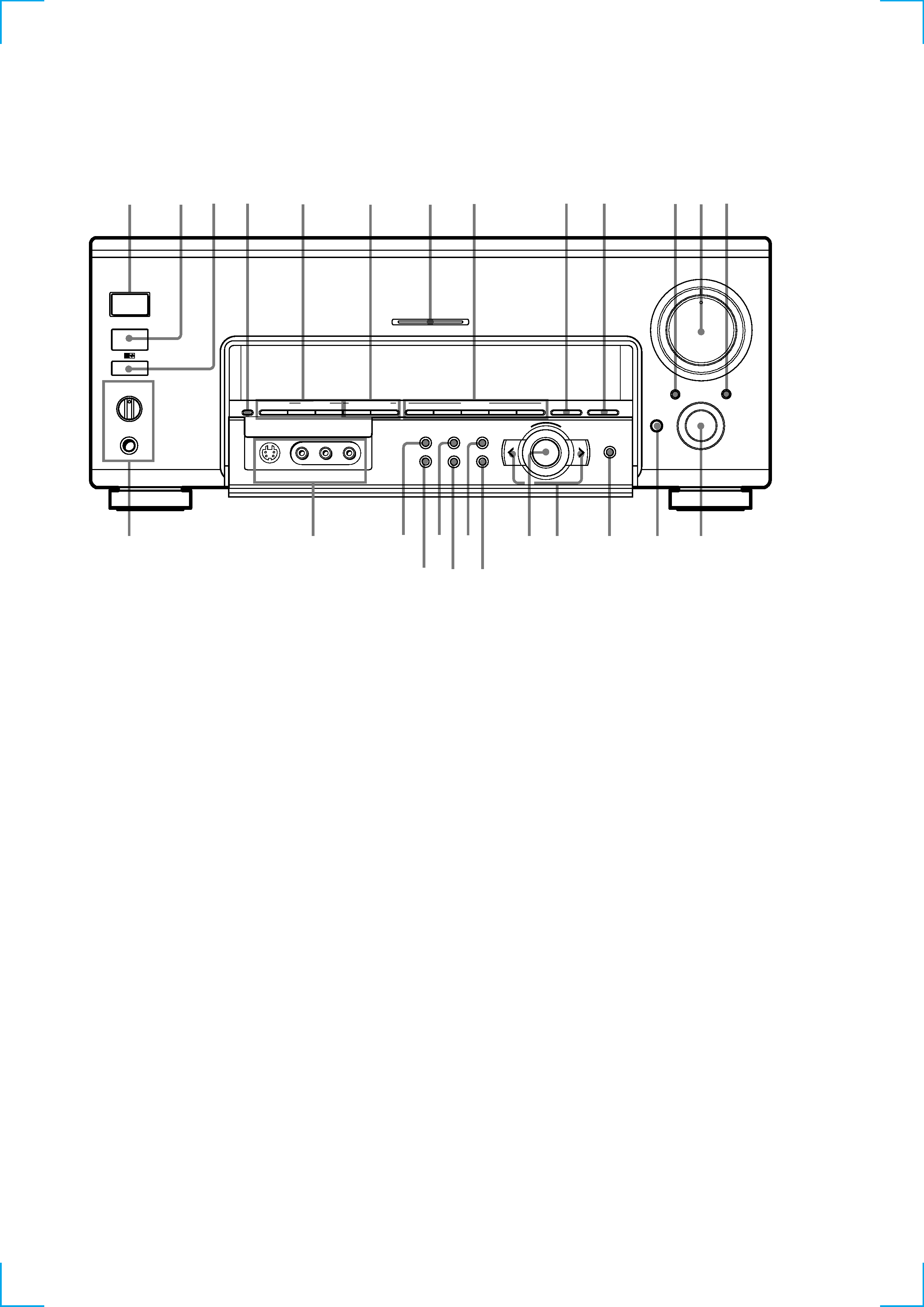
FRONT PANEL SECTION
1
?/1 switch
2
INPUT SELECTOR knob
3
AUDIO SPLIT button
4
DIGITAL/ANALOG button
5
5.1CH INPUT button
6
IR emitter
7
IR receptor
8
MEMORY button
9
TUNER PRESET +/ button
FM/AM button
0
SOUND FIELD PRESET +/ button
qa
MULTICHANNEL DECODING indicator
qs
A.F.D button
MODE +/ buttons
2CH button
ANALOG DIRECT button
qf
wg
qg
2
qd
5
3
4
qa
qs
wf
wh
wd
ws w;
qk qj
ql
wa
qh
9
q;
6
8
7
PHONES
SPEAKERS
A
OFF
A+B
B
MEMORY
+
+A.F.D
FM / AM
TUNER PRESET
0
10
MULTI CHANNEL DECODING
OPEN/
CLOSE
MASTER VOLUME
1
9
8
7
2
3
6
5
4
AUDIO SPLIT
DIGITAL / ANALOG
1/u
+
ENTER
EQ
SUR
LEVEL
TUNER
CUSTOM
SET UP
VIDEO
S-VIDEO
L
AUDIO
R
2 CH
ANALOG DIRECT
EQ BANK
5.1CH INPUT
SOUND FIELD PRESET
SOUND FIELD
INPUT
SELECTOR
MODE
1
qd
EQ BANK button
qf
MASTER VOLUME knob
qg
OPEN/CLOSE button
qh
ENTER button
qj
Cursor buttons (
I/i)
qk
Jog dial
ql
SET UP button
w;
LEVEL button
wa
CUSTOM button
ws
SUR button
wd
TUNER button
wf
EQ button
wg
SPEAKERS selector knob
PHONES jack
wh
VIDEO 3 jack
5
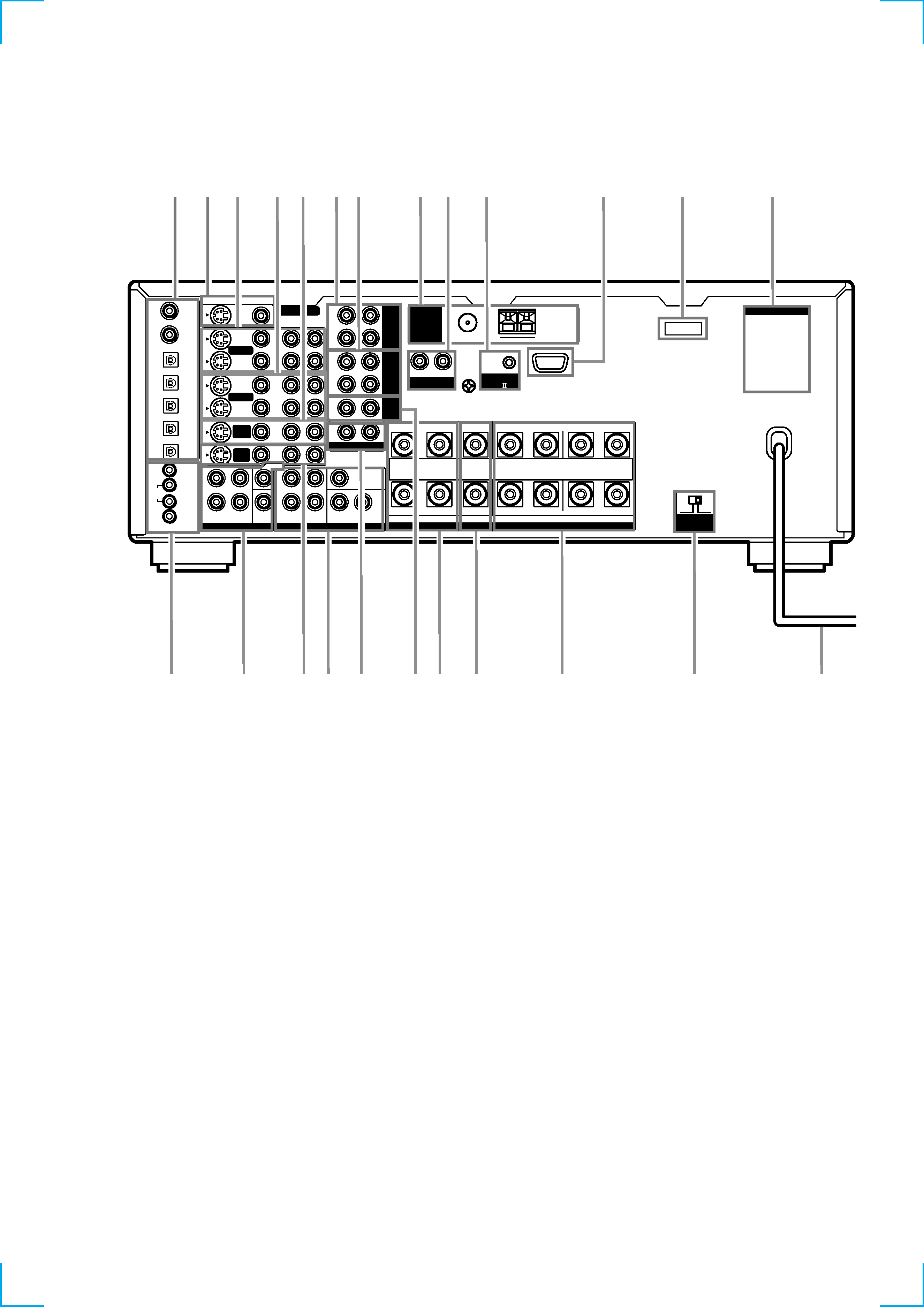
REAR PANEL SECTION
1
DIGITAL jack
2
MONITOR OUT jack
3
VIDEO 1 jack
4
VIDEO 2 jack
5
DVD/LD jack
6
TAPE jack
7
MD/DAT jack
8
ANTENNA
9
PHONO jack
0
CONTROL A1 II jack
qa
RS-232C
qs
VOLTAGE SELECRTOR switch
(E,PX model)
AC OUTLET
B
+
SPEAKERS
IMPEDANCE USE 4 - 16
FRONT
REAR
CENTER
A
L
R
L
R
L
R
R
L
R
L
R
IN
REC
OUT
IN
IN
OUT
IN
IN
IN
OUT
IN
CENTER
SUB WOOFER
REAR
FRONT
CENTER
SUB
WOOFER
REAR
FRONT
TV/
SAT
DVD/
LD
VIDEO 1
MONITOR OUT
VIDEO 2
REC
OUT
L
R
AUDIO
S-VIDEO
DVD/LD
IN COAX
CD
IN COAX
DVD/LD
IN OPT
TV/SAT
IN OPT
MD/DAT
IN OPT
MD/DAT
OUT OPT
CD
IN OPT
MONITOR
CTRL S
IN
STATUS
IN
CTRL S
OUT
VIDEO 1
DVD/
LD
TV/
SAT
VIDEO
L
2ND AUDIO OUT
PRE OUT
5.1CH INPUT
4
8
IMPEDANCE
SELECTOR
CONTROL
A1
TAPE
MD/
DAT
CD
L
SIGNAL GND
AM
y
y
FM 75
COAXIAL
ANTENNA
PHONO
R
3
4 5 67
8 9
q;
1 2
qs
qa
wf
wd
qd
ws wa w;
ql qk qj
qh
qg
qf
qd
AC OUTLET
qf
Power cord
qg
IMPEDANCE SELECTOR switch
qh
FRONT SPEAKER terminal
qj
CENTER SPEAKER terminal
qk
REAR SPEAKER terminal
ql
CD jack
w;
2ND AUDIO OUT jack
wa
PRE OUT jack
ws
TV/SAT jack
wd
5.1CH INPUT jack
wf
CONTROL S jack
(US,Canadian model)