1
US Model
Canadian Model
SERVICE MANUAL
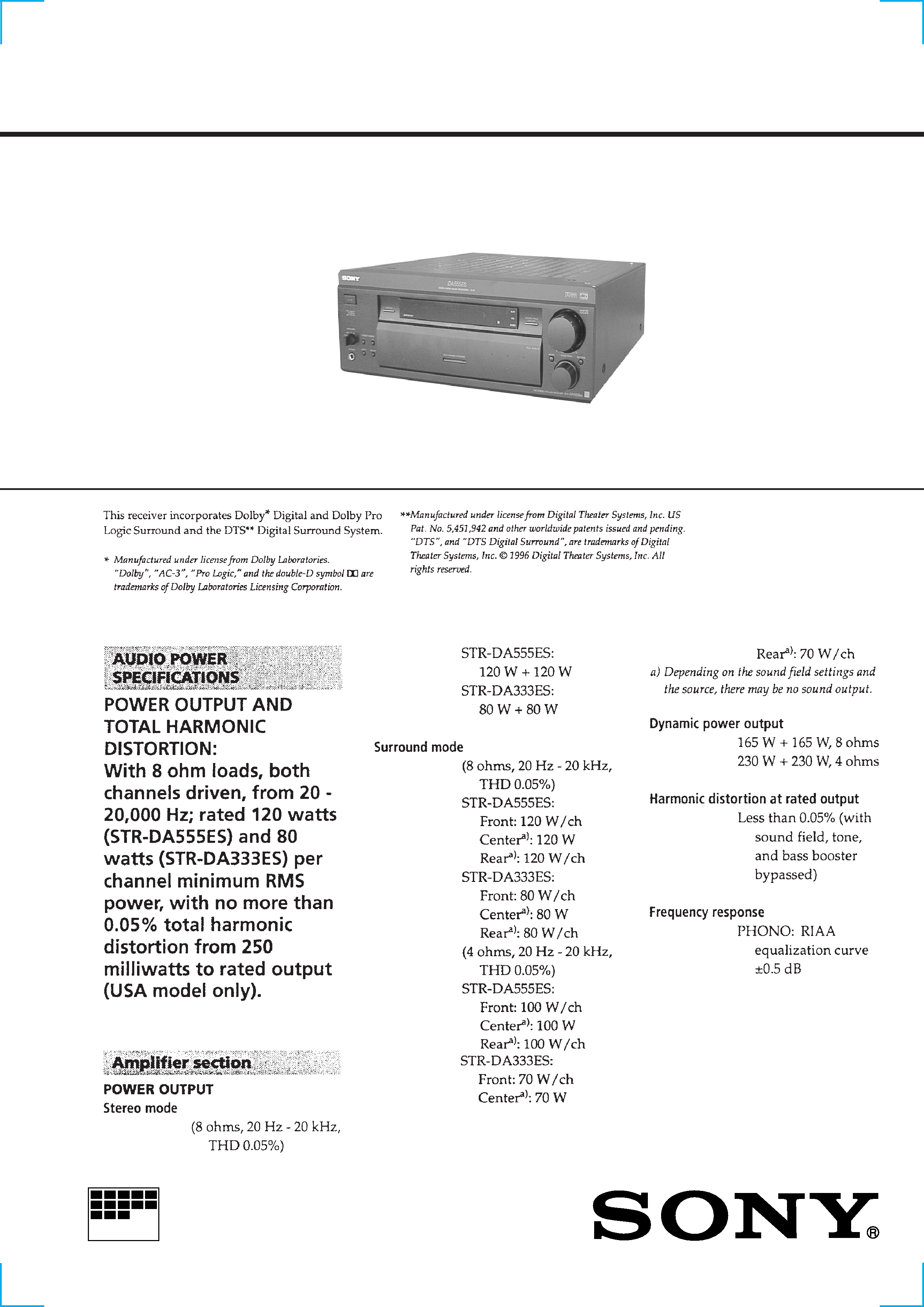
FM STEREO FM-AM RECEIVER
MICROFILM
SPECIFICATIONS
STR-DA333ES/DA555ES
-- Continued on next page --
Photo: STR-DA555ES
2
3
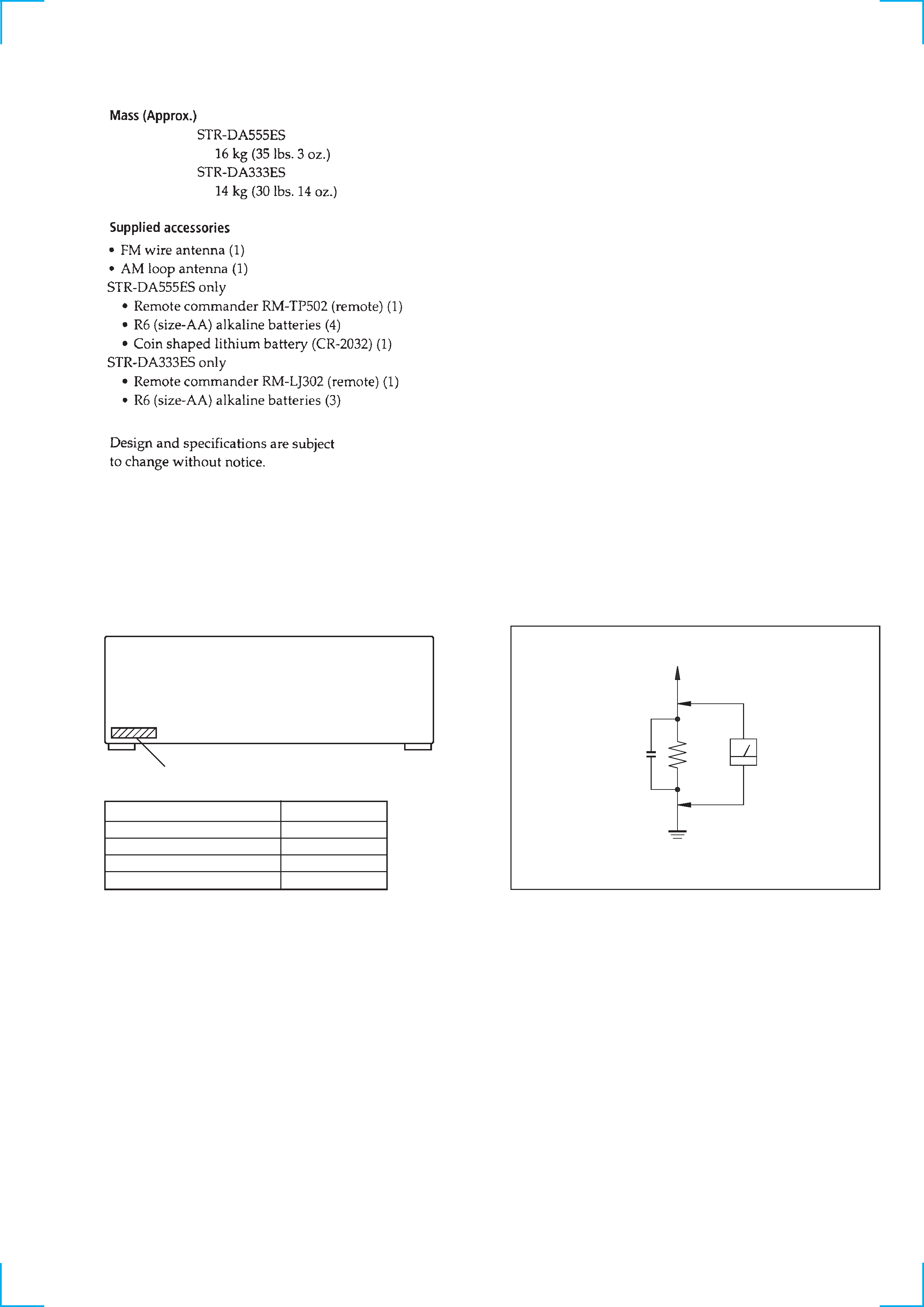
MODEL IDENTIFICATION
BACK PANEL
MODEL
PARTS No.
DA555ES:US model
4-219-066-0
DA555ES:Canadian model
4-219-066-1
DA333ES:US model
4-219-066-2
DA333ES:Canadian model
4-219-066-3
PART NO.
After correcting the original service problem, perform the fol-
lowing safety checks before releasing the set to the customer:
Check the antenna terminals, metal trim, "metallized" knobs, screws,
and all other exposed metal parts for AC leakage. Check leakage as
described below.
LEAKAGE
The AC leakage from any exposed metal part to earth ground and
from all exposed metal parts to any exposed metal part having a
return to chassis, must not exceed 0.5 mA (500 microampers). Leak-
age current can be measured by any one of three methods.
1. A commercial leakage tester, such as the Simpson 229 or RCA
WT-540A. Follow the manufacturers' instructions to use these
instruments.
2. A battery-operated AC milliammeter. The Data Precision 245
digital multimeter is suitable for this job.
3. Measuring the voltage drop across a resistor by means of a VOM
or battery-operated AC voltmeter. The "limit" indication is 0.75
V, so analog meters must have an accurate low-voltage scale.
The Simpson 250 and Sanwa SH-63Trd are examples of a pas-
sive VOM that is suitable. Nearly all battery operated digital
multimeters that have a 2V AC range are suitable. (See Fig. A)
SAFETY CHECK-OUT
To Exposed Metal
Parts on Set
0.15
µF
1.5 k
AC
Voltmeter
(0.75 V)
Earth Ground
Fig. A. Using an AC voltmeter to check AC leakage.
SAFETY-RELATED COMPONENT WARNING!!
COMPONENTS IDENTIFIED BY MARK
! OR DOTTED LINE WITH
MARK
! ON THE SCHEMATIC DIAGRAMS AND IN THE PARTS
LIST ARE CRITICAL TO SAFE OPERATION. REPLACE THESE
COMPONENTS WITH SONY PARTS WHOSE PART NUMBERS AP-
PEAR AS SHOWN IN THIS MANUAL OR IN SUPPLEMENTS PUB-
LISHED BY SONY.
ATTENTION AU COMPOSANT AYANT RAPPORT
À LA SÉCURITÉ!
LES COMPOSANTS IDENTIFÉS PAR UNE MARQUE
! SUR LES
DIAGRAMMES SCHÉMATIQUES ET LA LISTE DES PIÈCES SONT
CRITIQUES POUR LA SÉCURITÉ DE FONCTIONNEMENT. NE
REMPLACER CES COMPOSANTS QUE PAR DES PIÈSES SONY
DONT LES NUMÉROS SONT DONNÉS DANS CE MANUEL OU
DANS LES SUPPÉMENTS PUBLIÉS PAR SONY.

4
TABLE OF CONTENTS
1.
SERVICE NOTE ··························································· 5
2.
GENERAL ······································································ 6
3.
TEST MODE ···························································· 9
4.
ELECTRICAL ADJUSTMENT ························· 10
5.
DIAGRAMS
5-1.
Block Diagram
· Main Section ·································································· 11
· Tuner Section ································································· 13
· Power Section ································································ 15
5-2.
Circuit Boards Location ··················································· 17
5-3.
Schematic Diagram Digital (1/3) Section ················· 19
5-4.
Schematic Diagram Digital (2/3) Section ················· 21
5-5.
Schematic Diagram Digital (3/3) Section ················· 23
5-6.
Printed Wiring Board Digital Section ························ 25
5-7.
Printed Wiring Board Main Section ··························· 27
5-8.
Schematic Diagram Main Section (1/3) ····················· 29
5-9.
Schematic Diagram Main Section (2/3) ····················· 31
5-10. Schematic Diagram Main Section (3/3) ····················· 33
5-11. Schematic Diagram AMP Section ······························ 35
5-12. Printed Wiring Board AMP Section ··························· 37
5-13. Schematic Diagram Video Section ····························· 39
5-14. Printed Wiring Board Video Section ·························· 41
5-15. Schematic Diagram Display Section ·························· 43
5-16. Printed Wiring Board Display Section ······················· 45
5-17. Schematic Diagram Speaker Section ························· 47
5-18. Printed Wiring Board Speaker Section ······················· 49
5-19. Printed Wiring Board Audio Section ·························· 51
5-20. Schematic Diagram Audio Section ···························· 52
5-21. Schematic Diagram Input Section ······························ 53
5-22. Printed Wiring Board Input Section ··························· 54
5-23. Schematic Diagram Power Section ···························· 55
5-24. Printed Wiring Board Power Section ························· 57
5-25. IC Block Diagrams ··························································· 59
5-26. IC Pin Function Description ············································· 63
6.
EXPLODED VIEWS
6-1.
Front Panel Section ·························································· 71
6-2.
Chassis Section ································································· 72
7.
ELECTRICAL PARTS LIST ··································· 74
5
Track No.
1
2
3
4
5
SECTION 1
SERVICE NOTE
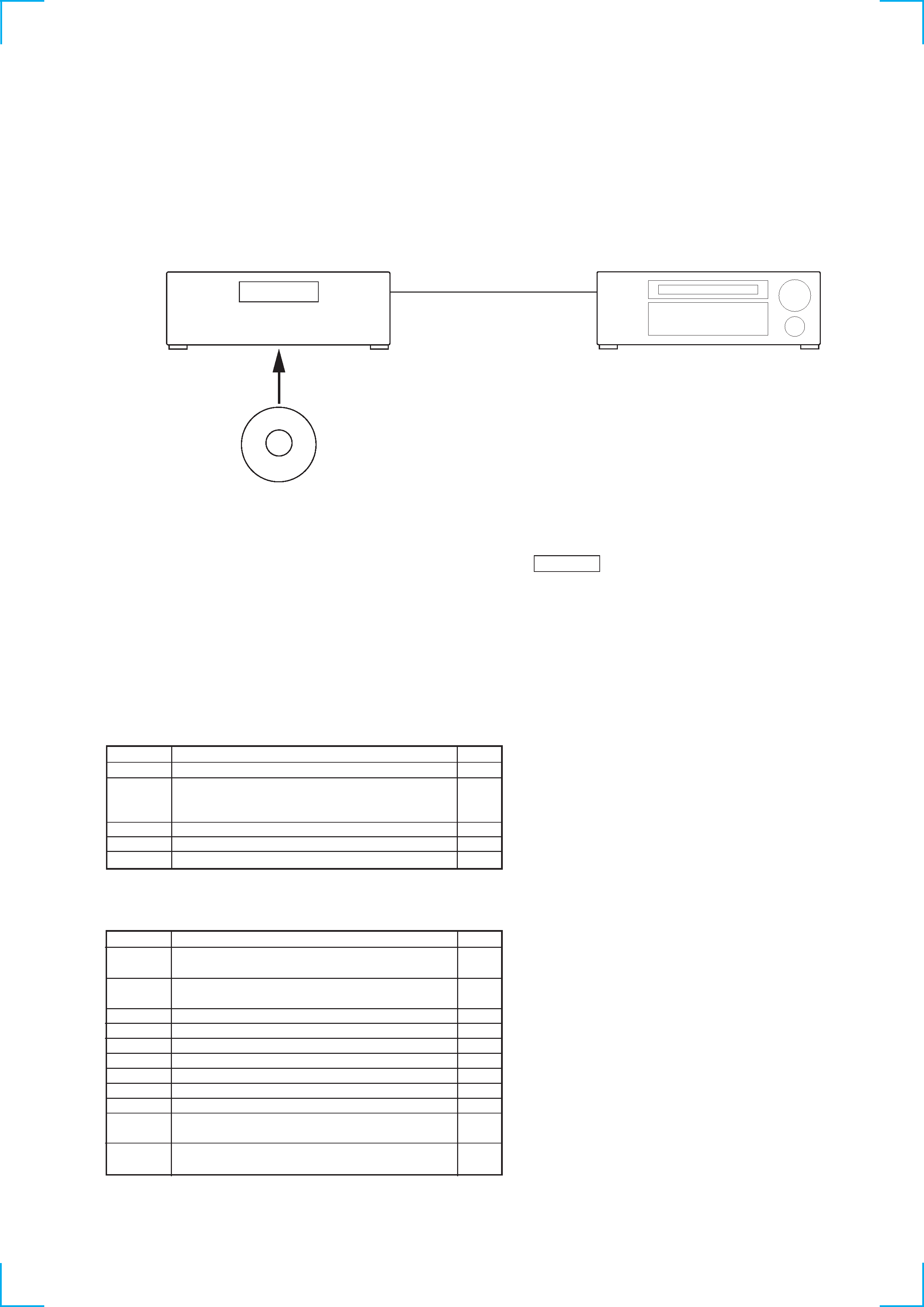
DTS Decode Test
· Required Instrument
CD player (equipped with optical digital output)
Optical cable
DTS test CD (J-2501-154-A)
Connection:
Time
5'40"
4'16"
4'08"
3'29"
6'42"
Music Demonstration
Contents
Seal : "Prayer for the Dying"
Andrew Litton conducting
The Dallas Symphony Orchestra & Chorus:
Excerpt from Tchaikovsky: "1812 Overture"
Alan Parsons with Christopher Cross: "So Far Away"
Shoelss Joe: "The Bet"
TELARC: "A Touch of Surround Madness"
Procedure:
1. Set the FUNCTION of the receiver to the CD position and confirm that " OPTICAL " and "CD" appear on the display.
2. Insert the DTS test CD into the CD player and play the CD.
3. About three seconds later, confirm that the receiver recognizes the optical signal and that the "DTS" and "dts [3/2]" are appear on the
display. Confirm also that MULTI CHANNEL DECODING (blue lamp) flashes on the front panel.
Track No.
6
7
8
9
10
11
12
13
14
15
16
Set-Up
Contents
1 kHz sine (All channels)
Level Adjustment and Harmonic Distortion Analysis
100 Hz sine (All channels)
Verification of Signal and Subwoofer Testing
C-Weighted Pink Noise-Left Front Channel
C-Weighted Pink Noise-Center Channel
C-Weighted Pink Noise-Right Front Channel
C-Weighted Pink Noise-Right Rear Channel
C-Weighted Pink Noise-Left Rear Channel
C-Weighted Pink Noise-Subwoofer (LEE)
C-Weighted Pink Noise-All Channels
10 Hz to 20 kHz Sine Sweep
An "All Channel" Frequency Response Test
20 Hz to 160 Hz sine sweep
A "Subwoofer" Low Frequency Response Test
* Track numbers from 8 to 14 are for Room Equalization and Channel Identification.
1 CD player
2 Optical
digital output
3 Optical input
Receiver STR-DA555ES/DA333ES
5 DTS test CD (Music Demonstration and Set Up Disc)
Time
1'00"
1'00"
1'00"
2'00"
2'00"
2'00"
2'00"
2'00"
2'00"
2'00"
2'00"