MICROFILM
SERVICE MANUAL
MICRO SATELLITE SYSTEM
US Model
Canadian Model
AEP Model
UK Model
E Model
SPECIFICATIONS
SA-VE502/VE505/
WMS5/SS-MS5
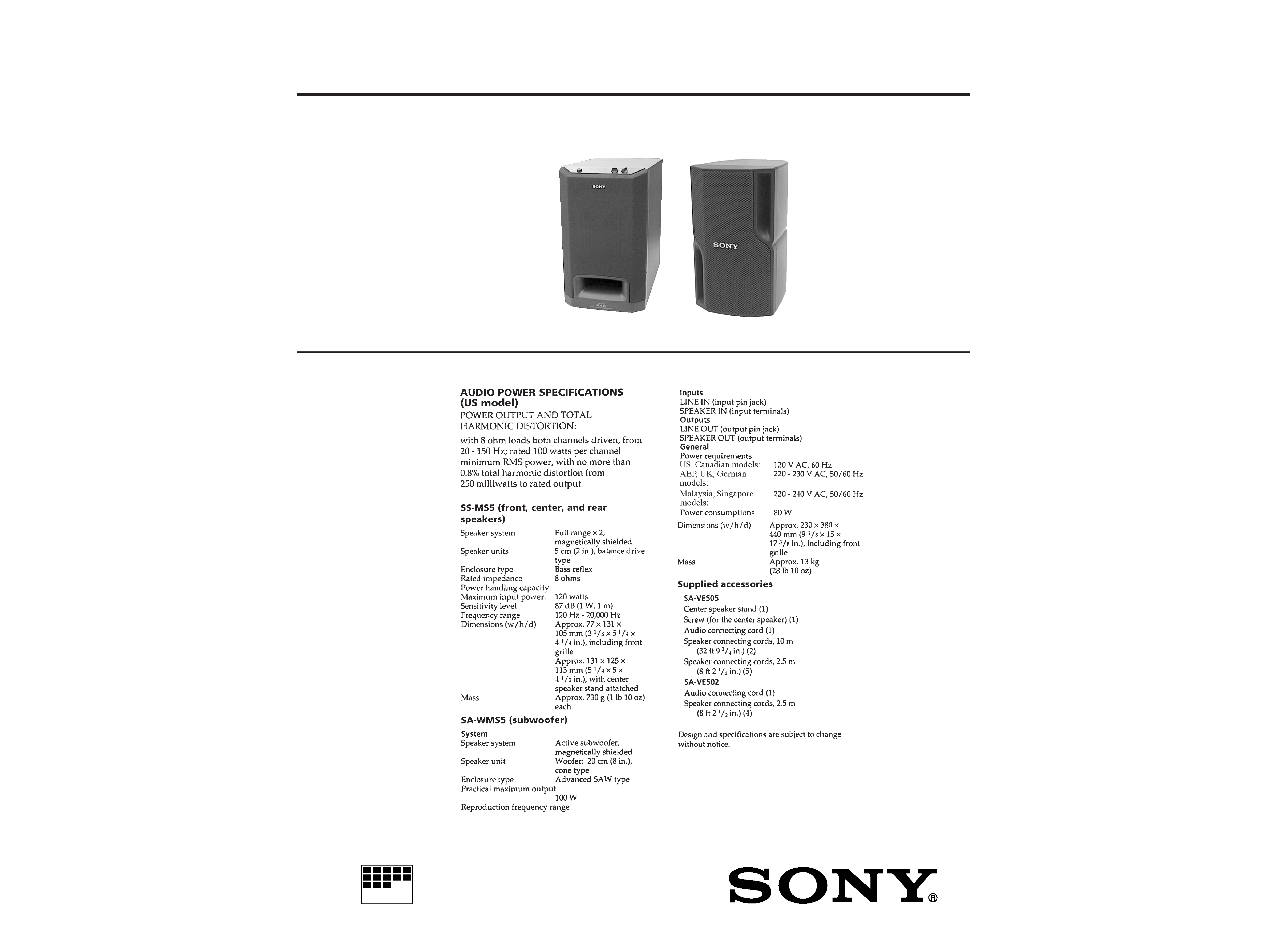
The SA-VE502 system consists of one unit
of SA-WMS5 and two units of SS-MS5.
The SA-VE505 system consists of one unit
of SA-WMS5 and five units of SS-MS5.
Photo: SA-WMS5
Photo: SS-MS5
2
ATTENTION AU COMPOSANT AYANT RAPPORT
À LA SÉCURITÉ!
LES COMPOSANTS IDENTIFIÉS PAR UNE MARQUE
!
SUR LES DIAGRAMMES SCHÉMATIQUES ET LA LISTE
DES PIÈCES SONT CRITIQUES POUR LA SÉCURITÉ
DE FONCTIONNEMENT. NE REMPLACER CES COM-
POSANTS QUE PAR DES PIÈCES SONY DONT LES
NUMÉROS SONT DONNÉS DANS CE MANUEL OU
DANS LES SUPPLÉMENTS PUBLIÉS PAR SONY.
SAFETY-RELATED COMPONENT WARNING!!
COMPONENTS IDENTIFIED BY MARK
! OR DOTTED
LINE WITH MARK
! ON THE SCHEMATIC DIAGRAMS
AND IN THE PARTS LIST ARE CRITICAL TO SAFE
OPERATION. REPLACE THESE COMPONENTS WITH
SONY PARTS WHOSE PART NUMBERS APPEAR AS
SHOWN IN THIS MANUAL OR IN SUPPLEMENTS PUB-
LISHED BY SONY.
SAFETY CHECK-OUT
After correcting the original service problem, perform the follow-
ing safety check before releasing the set to the customer:
Check the antenna terminals, metal trim, "metallized" knobs,
screws, and all other exposed metal parts for AC leakage.
Check leakage as described below.
LEAKAGE TEST
The AC leakage from any exposed metal part to earth ground and
from all exposed metal parts to any exposed metal part having a
return to chassis, must not exceed 0.5 mA (500 microampers.).
Leakage current can be measured by any one of three methods.
1. A commercial leakage tester, such as the Simpson 229 or RCA
WT-540A. Follow the manufacturers' instructions to use these
instruments.
2. A battery-operated AC milliammeter. The Data Precision 245
digital multimeter is suitable for this job.
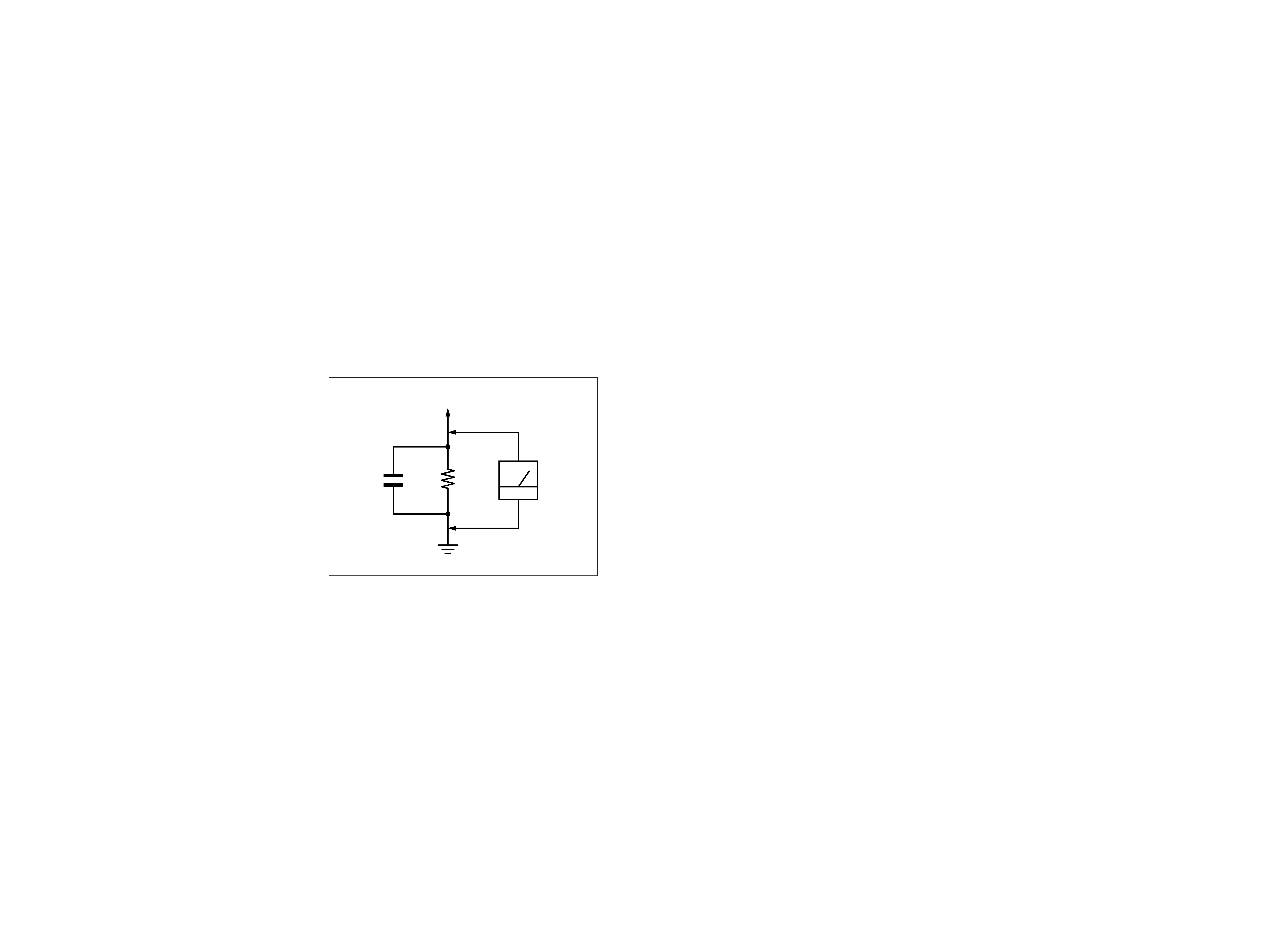
3. Measuring the voltage drop across a resistor by means of a
VOM or battery-operated AC voltmeter. The "limit" indica-
tion is 0.75 V, so analog meters must have an accurate low-
voltage scale. The Simpson 250 and Sanwa SH-63Trd are ex-
amples of a passive VOM that is suitable. Nearly all battery
operated digital multimeters that have a 2 V AC range are suit-
able. (See Fig. A)
Fig. A.
Using an AC voltmeter to check AC leakage.
1.5 k
0.15
µF
AC
voltmeter
(0.75 V)
To Exposed Metal
Parts on Set
Earth Ground
3
4
SECTION 1
GENERAL
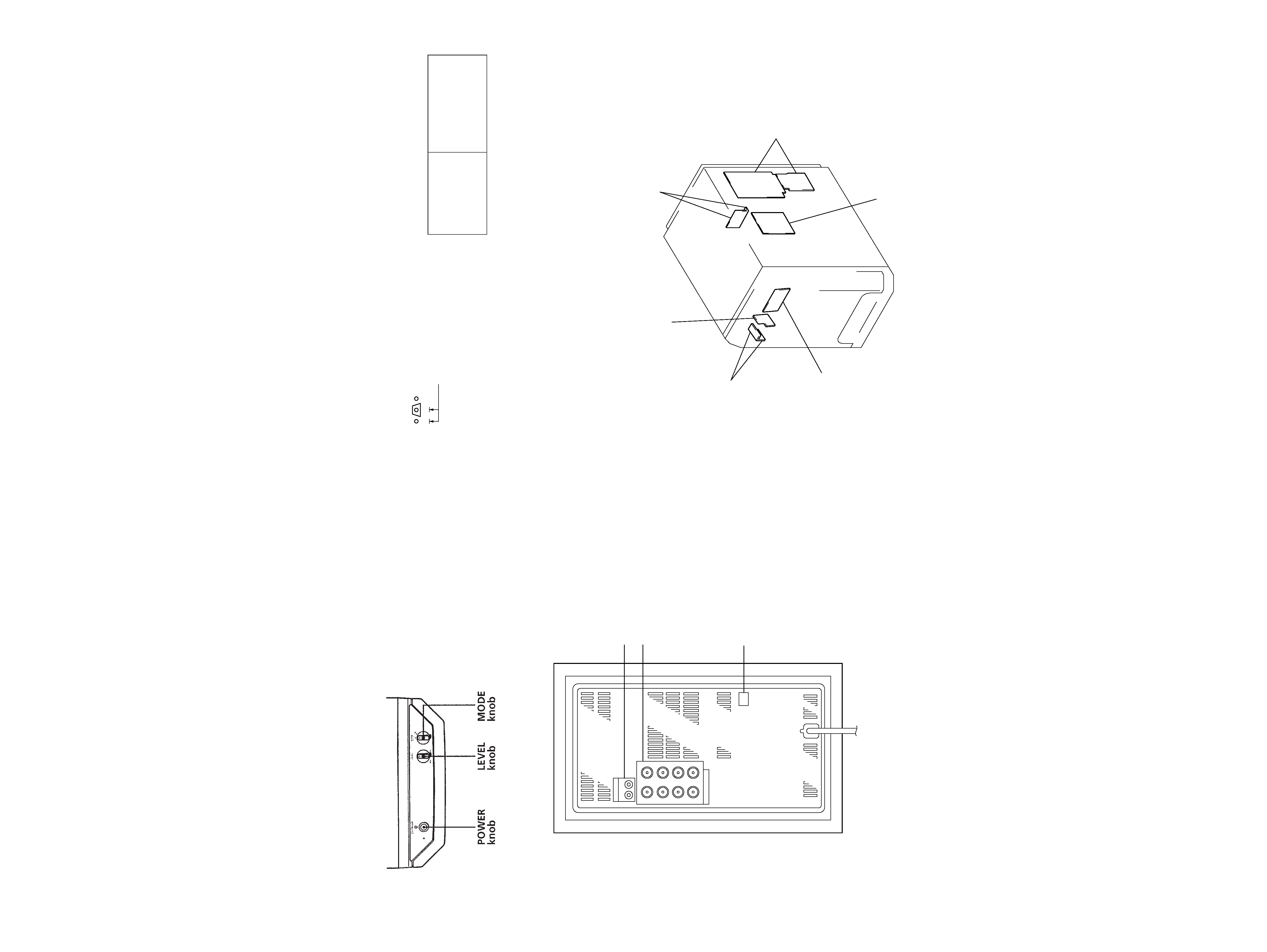
· Location of Controls
SA-WMS5
Front view
Rear view
SECTION 2
DIAGRAMS
2-1.
NOTE FOR PRINTED WIRING BOARDS AND SCHEMATIC DIAGRAMS
Note on Printed Wiring Board:
· X : parts extracted from the component side.
· b : Pattern from the side which enables seeing.
(The other layers' patterns are not indicated.)
· Indication of transistor.
B
These are omitted.
CE
Q
Note on Schematic Diagram:
· All capacitors are in µF unless otherwise noted. pF: µµF
50 WV or less are not indicated except for electrolytics
and tantalums.
· All resistors are in
and 1/4 W or less unless otherwise
specified.
· 2 : nonflammable resistor.
· C : panel designation.
· U : B+ Line.
· V : B Line.
· Voltages are dc with respect to ground under no-signal
conditions.
no mark : AUDIO
· Voltages are taken with a VOM (input impedance 10 M
).
Voltage variations may be noted due to normal produc-
tion tolerances.
· Signal path.
F
: AUDIO
· Abbreviation
CND : Canadian
Note:
The components identi-
fied by mark
! or dotted
line with mark
! are criti-
cal for safety.
Replace only with part
number specified.
Note:
Les composants identifiés par
une marque
! sont critiques
pour la sécurité.
Ne les remplacer que par une
piéce portant le numéro
spécifié.
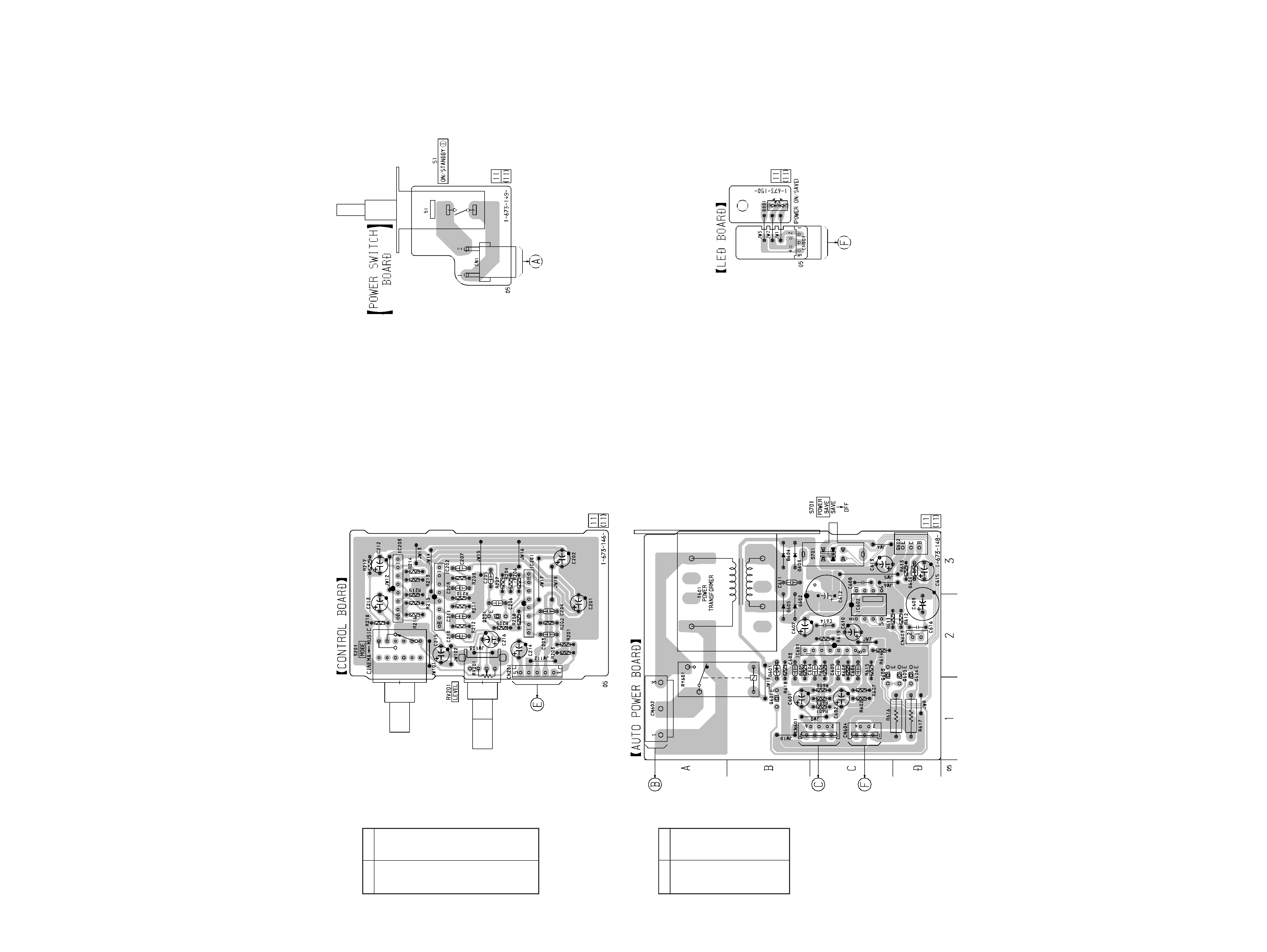
· Circuit Boards Location
SA-WMS5
POWER SWITCH board
POWER board
LED board
CONTROL board
AUTO POWER board
MAIN board
LINE IN/OUT jack
SPEAKER IN/OUT
terminal
POWER SAVE
switch
SA-VE502/VE505/WMS5/SS-MS5
5
6
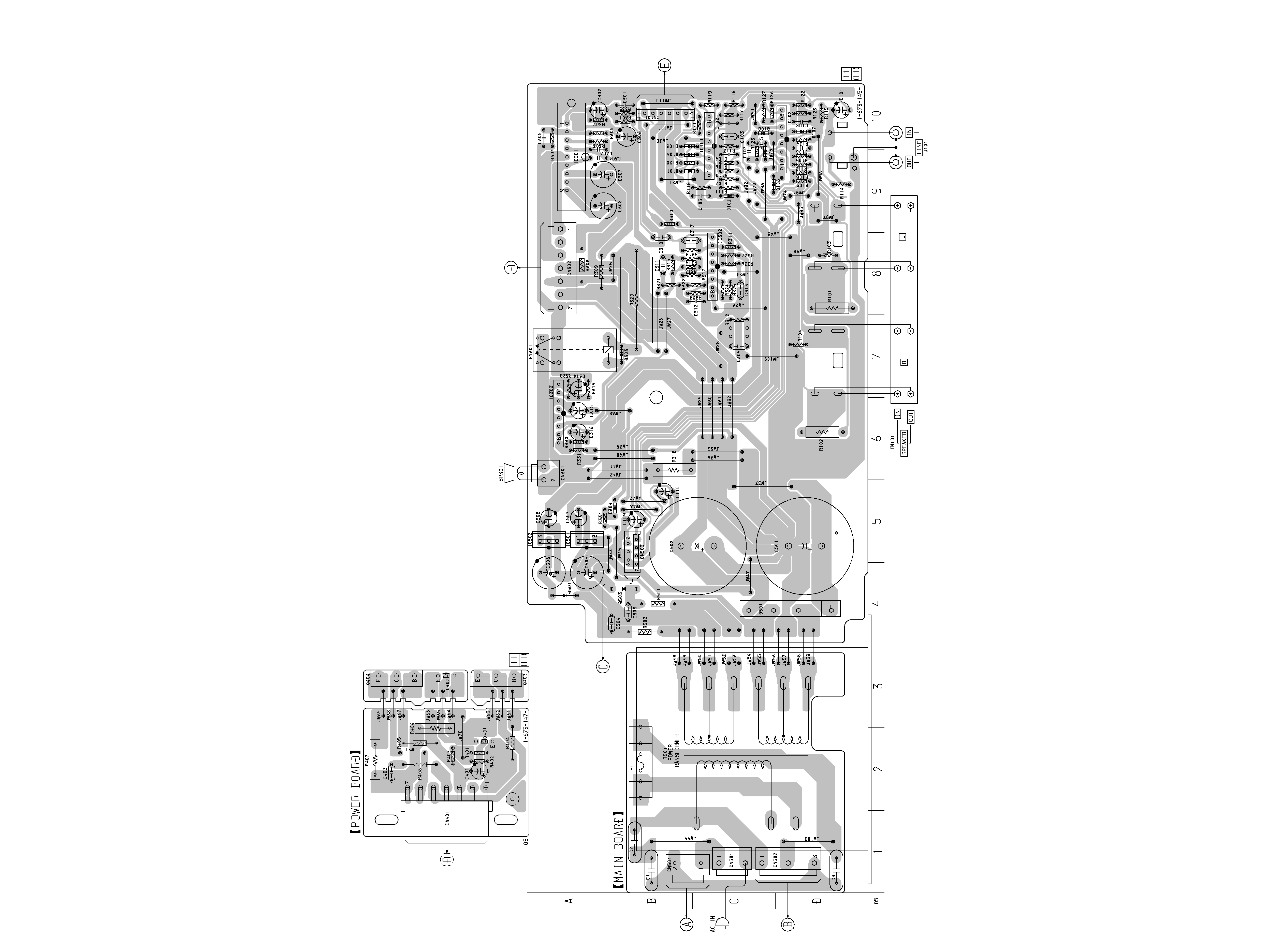
2-2.
PRINTED WIRING BOARDS
· See page 4 for Circuit Boards Location.
(Page 6)
(Page 8)
(Page 7)
(Page 7)
(Page 7)
(Page 5)
SA-VE502/VE505/WMS5/SS-MS5
· Semiconductor
Location
MAIN Board
Ref. No.
Location
D101
B-9
D102
C-9
D103
B-10
D104
B-9
D105
C-9
D106
C-9
D107
D-10
D108
C-10
D303
B-7
D304
B-5
D501
D-4
D503
B-4
D504
A-4
IC101
C-10
IC102
D-10
IC301
A-9
IC302
C-8
IC303
A-6
IC501
A-5
IC502
A-5
D601
B-2
D602
B-2
D603
B-3
D604
B-3
D605
B-2
D606
D-3
IC601
C-2
IC602
C-2
Q601
B-1
Q602
D-3
Q603
C-2
Q604
D-2
Q605
D-2
· Semiconductor
Location
AUTO POWER Board
Ref. No.
Location
7
8
(Page 6)
(Page 5)
(Page 5)
(Page 8)
(Page 5)
(Page 7)