2
English
Owner's Record
The model and serial numbers are located at the rear.
Record these numbers in the spaces provided below.
Refer to these numbers whenever you call upon your
Sony dealer regarding this product.
Model No.
Serial No.
WARNING
To prevent fire or shock hazard, do not
expose the unit to rain or moisture.
Dangerously high voltage are present
inside the unit.
Do not open the cabinet. Refer servicing
to qualified personnel only.
In the event of a malfunction or when maintenance is
necessary, consult an authorized Sony dealer.
For the customers in the U.S.A.
This equipment has been tested and found to comply with
the limits for a Class A digital device, pursuant to Part 15 of
the FCC Rules. These limits are designed to provide
reasonable protection against harmful interference when the
equipment is operated in a commercial environment.
This equipment generates, uses, and can radiate radio
frequency energy and, if not installed and used in
accordance with the instruction manual, may cause harmful
interference to radio communications. Operation of this
equipment in a residential area is likely to cause harmful
interference in which case the user will be required to correct
the interference at his own expense.
You are cautioned that any changes or modifications not
expressly approved in this manual could void your authority
to operate this equipment.
For the customers in the United Kingdom
WARNING
THIS APPARATUS MUST BE EARTHED
IMPORTANT
The wires in this mains lead are coloured in accordance with
the following code:
Green-and-yellow:
Earth
Blue:
Neutral
Brown:
Live
As the colours of the wires in the mains lead of this
apparatus may not correspond with the coloured markings
identifying the terminals in your plug proceed as follows:
The wire which is coloured green-and-yellow must be
connected to the terminal in the plug which is marked by the
letter E or by the safety earth symbol
Y or coloured green or
green-and-yellow.
The wire which is coloured blue must be connected to the
terminal which is marked with the letter N or coloured black.
The wire which is coloured brown must be connected to the
terminal which is marked with the letter L or coloured red.
Ensure that your equipment is connected correctly - If you
are in any doubt consult a qualified electrician.
ATTENTION:
Picture distortion may occur if this monitor is positioned
in close proximity to any equipment emitting
electromagnetic radiation.

3
On safety
· Operate the unit only with a power source as
specified in "Specifications" section.
· The nameplate indicating operating voltage, power
consumption, etc., is located on the rear.
· Should any solid object or liquid fall into the cabinet,
unplug the unit and have it checked by qualified
personnel before operating it any further.
· Do not drop or place heavy objects on the power
cord. If the power cord is damaged, turn off the
power immediately. It is dangerous to use the unit
with a damaged power cord.
· Unplug the unit from the wall outlet if it is not to be
used for several days or more.
· Disconnect the power cord from the AC outlet by
grasping the plug, not by pulling the cord.
· The socket-outlet shall be installed near the
equipment and shall be easily accessible.
On installation
· Allow adequate air circulation to prevent internal heat
build-up.
Do not place the unit on surfaces (rugs, blankets, etc.)
or near materials (curtains, draperies) that may block
the ventilation holes.
· Do not install the unit in a location near heat sources
such as radiators or air ducts, or in a place subject to
direct sunlight, excessive dust, mechanical vibration
or shock.
On cleaning
To keep the unit looking brand-new, periodically clean
it with a mild detergent solution. Never use strong
solvents such as thinner or benzine, or abrasive
cleansers since they will damage the cabinet. As a
safety precaution, unplug the unit before cleaning it.
On repacking
Do not throw away the carton and packing materials.
They make an ideal container which to transport the
unit.
If you have any questions about this unit, contact your
authorized Sony dealer.
Table of Contents
EN
Precaution
English
About this manual
Before operating the unit, please read this manual
thoroughly and retain it for future reference.
The explanation given in this manual can be applied to
the following models unless noted otherwise.
When explanation differs among models, this is clearly
indicated in this manual.
· SSM-14N5E/14N5U/14N5A (14-inch monitor)
· SSM-20N5E/20N5U/20N5A (20-inch monitor)
Illustrations of the video monitor are for the
SSM-20N5E/20N5U/20N5A.
Features ............................................................ 4
Location and Function of Parts and Controls 5
Front .................................................................... 5
Rear Panel ........................................................... 6
Connections ..................................................... 7
How to Connect the AC Power Cord .................. 7
How to Connect a Cable to a BNC Connector .... 7
Using On-Screen Menus .................................. 8
On-Screen Menu Configuration .......................... 8
Operation through On-Screen Menus.................. 9
Functions of On-Screen Menus ......................... 10
Troubleshooting ............................................. 12
Specifications ................................................. 13
4
1) Trinitron
"Trinitron" is a registered trademark of Sony Corporation.
2) NTSC4.43
The NTSC4.43 system refers to an NTSC color system in which the subcarrier frequency is modified to 4.43 MHz. When an
NTSC recorded video program is played back with a Trident (PAL/SECAM/NTSC4.43) VTR, the NTSC4.43 signal is output.
Features
Picture
Fine pitch Trinitron1) picture tube
The fine pitch Trinitron tube provides a high resolution
picture. Horizontal resolution is more than 500 TV
lines at the center of the picture.
Comb filter
When NTSC video signals are received, a comb filter
activates to make more accurate Y/C separation. This
contributes to less of a decrease in resolution, cross
color and cross luminance phenomena.
Beam current feedback circuit
The built-in beam current feedback circuit assures
stable white balance.
Four color system available
The monitor can display NTSC, PAL, SECAM, and
NTSC4.432) signals. The appropriate color system is
selected automatically.
Input
Y/C input connector
The video signal, split into the chrominance signal (C)
and the luminance signal (Y), can be input through this
connector, eliminating the interference between the
two signals, which tends to occur in a composite video
signal, ensuring video quality.
Automatic termination
(connector with
mark only)
The input connector is terminated at 75 ohms inside
when no cable is connected to the loop-through output
connector. When a cable is connected to an output
connector, the 75-ohm termination is automatically
released.
Functions
On-screen menus
You can set monitor operation settings by using the
on-screen menus.
EIA standard 19-inch rack mounting
By using an MB-502B mounting bracket (for a 14-inch
monitor, not supplied) or SLR-103A slide rail (for a
20-inch monitor, not supplied), the monitor can be
mounted in an EIA standard 19-inch rack.
Attention when the product is installed in a rack:
· Elevated operating ambient temperature
If installed in a closed or multi-unit rack
assembly, the operating ambient temperature of
the rack environment may be greater than room
ambient.
Therefore, consideration should be given to
installing the equipment in an environment
compatible with the manufacturer's maximum
rated ambient temperature of 0 to +35 ºC (Tmra).
· Reduced air flow
Installation of the equipment in a rack should be
such that the amount of air flow required for safe
operation of the equipment is not compromised.
· Mechanical loading
Mounting of the equipment in the rack should be
such that a hazardous condition is not achieved
due to uneven mechanical loading.
· Circuit overloading
Consideration should be given to the connection
of the equipment to the supply circuit and the
effect that overloading of circuits might have on
overcurrent protection and supply wiring.
Appropriate consideration of equipment
nameplate ratings should be used when
addressing this concern.
· Reliable earthing
Reliable earthing of rack-mounted equipment
should be maintained. Particular attention should
be given to supply connections other than direct
connections to the branch circuit (e.g., use of
power strips).
..........................................................................................................................................................................................................
5
Location and Function of Parts and Controls
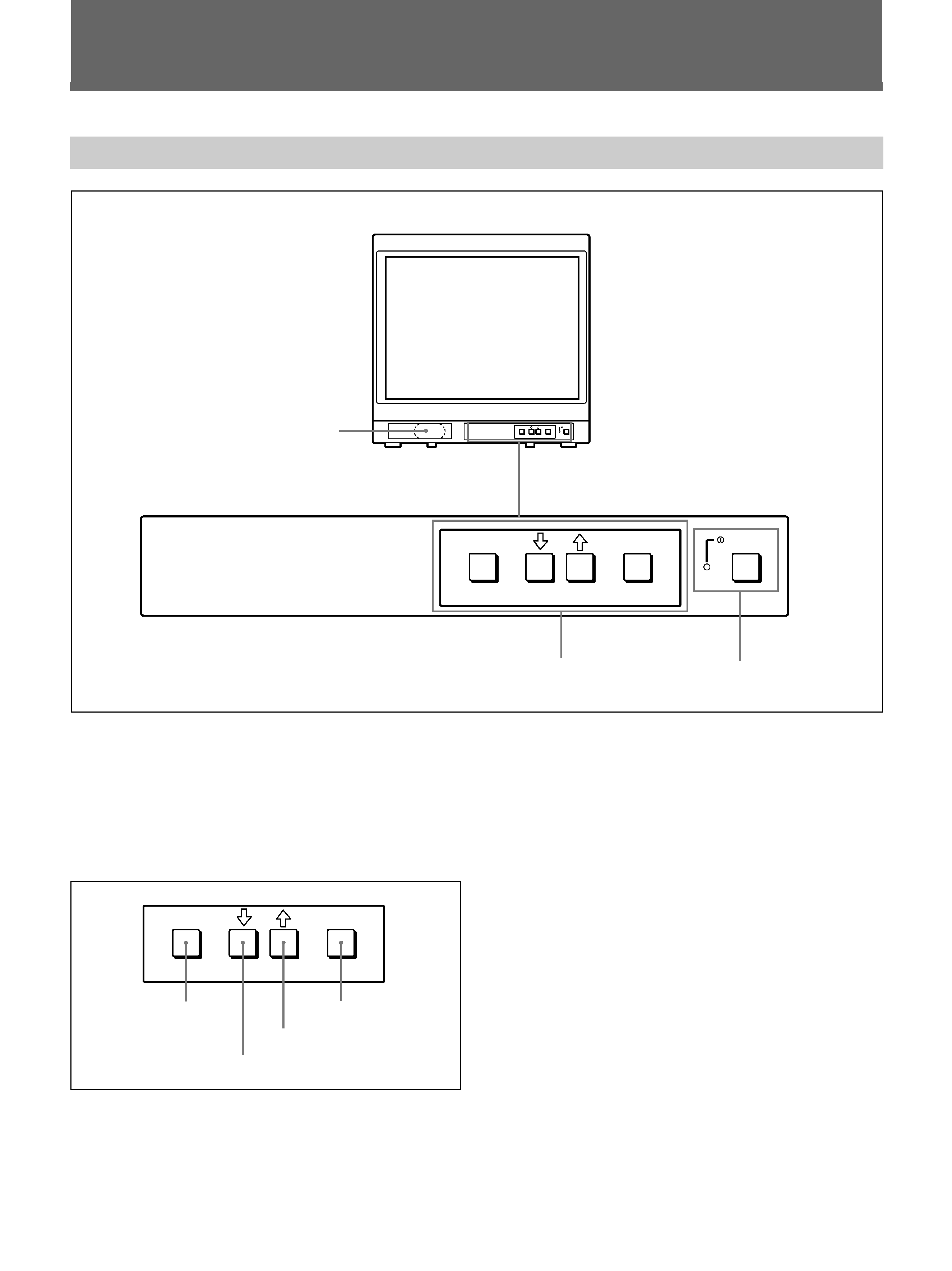
Front
ENTER
MENU/
EXIT
POWER
ENTER
MENU/
EXIT
POWER
1 Speaker
2 MENU buttons
3 UPOWER switch
and indicator
ENTER
MENU/
EXIT
MENU/EXIT button
. button
> button
ENTER button
1 Speaker
2 MENU buttons
Press to make the menu appear.
For detailed information on MENU buttons, see "Operation
through On-Screen Menus" on page 9.
3 UPOWER switch and indicator
Press to turn the monitor on. The indicator lights in
green.
To turn the power off, press this again.
6
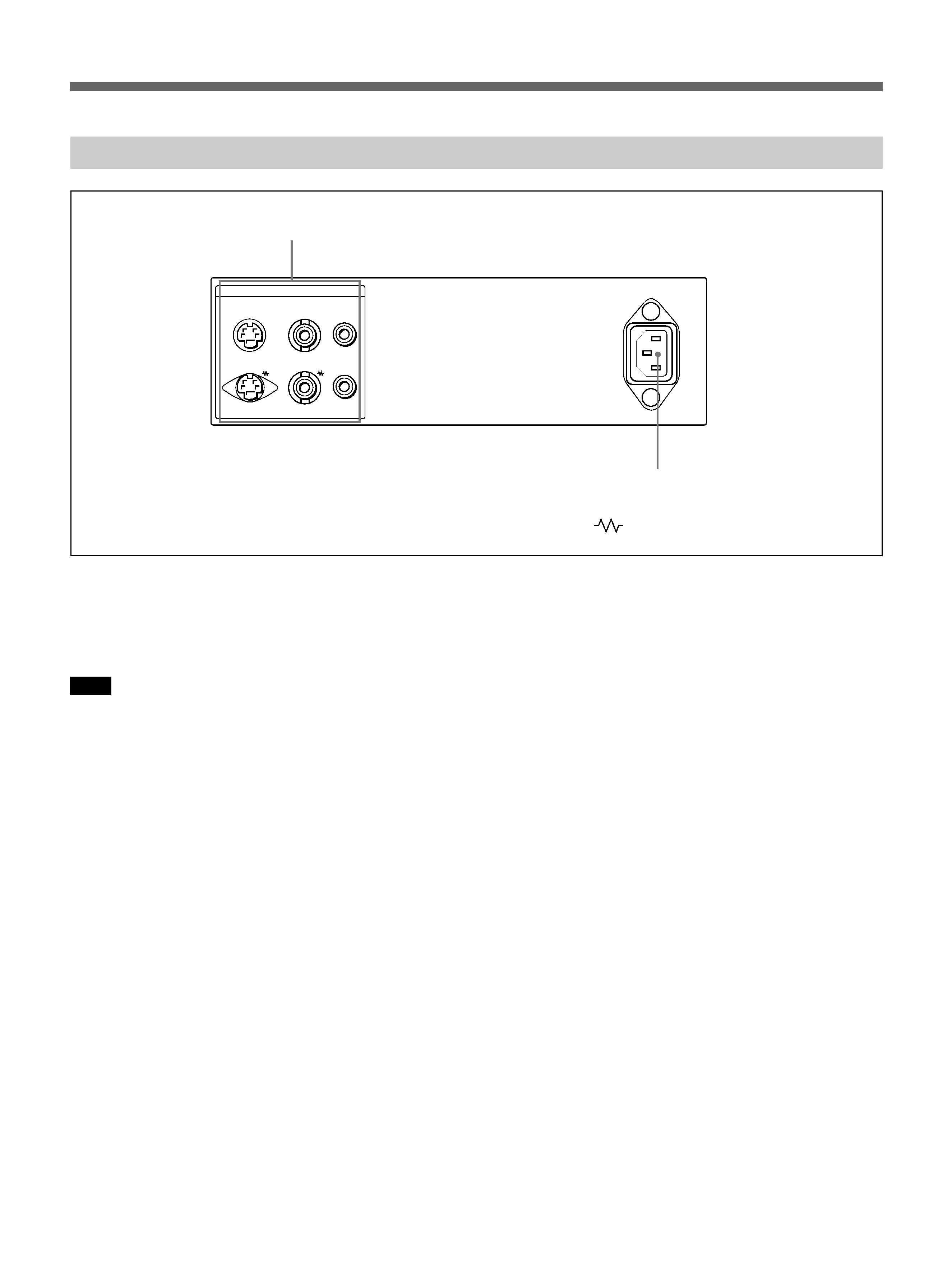
Rear Panel
Location and Function of Parts and Controls
1 LINE connectors
Input connectors for the composite video, Y/C separate
video and audio signals and their loop-through output
connectors.
Note
The Y/C IN connector has priority over the VIDEO IN
connector.
When connecting the cable to the Y/C IN connector,
the Y/C IN connector is automatically selected and the
VIDEO IN connector is disconnected even if the cable
is connected.
Y/C IN connector (4-pin mini-DIN)
Connect to the Y/C separate output connector of a
video camera, VCR or other video equipment.
Y/C OUT connector (4-pin mini-DIN)
Loop-through output of the Y/C IN connector.
Connect to the Y/C separate input connector of a VCR
or another monitor.
When the cable is connected to this connector, the 75-
ohm termination of the input is automatically released,
and the signal input to the Y/C IN connector is output
from this connector.
VIDEO IN connector (BNC-type)
Connect to the video output connector of video
equipment, such as a VCR or a color video camera.
For a loop-through connection, connect to the video
output connector of another monitor.
VIDEO OUT connector (BNC-type)
Loop-through output of the VIDEO IN connector.
Connect to the video input connector for a VCR or
another monitor.
When the cable is connected to this connector, the 75-
ohm termination of the input is automatically released,
and the signal input to the VIDEO IN connector is
output from this connector.
AUDIO IN connector (phono jack)
Connect to the audio output connector of a VCR or
other equipment. For a loop-through connection,
connect to the audio output of another monitor.
AUDIO OUT connector (phono jack)
Loop-through output of the AUDIO IN connector.
Connect to the audio input connector of a VCR or
another monitor.
2 /AC IN (inlet) connector
Connect the supplied AC power cord to this connector
and to a wall outlet.
(The
mark indicates automatic termination.)
2 /AC IN connector
1 LINE connectors
LINE
~ AC IN
Y/C
IN
VIDEO
IN
AUDIO
IN
OUT
OUT
OUT