SA-VE312/VE315/WMS315/
SS-CN315/V315
US Model
Canadian Model
AEP Model
UK Model
E Model
Australian Model
SERVICE MANUAL
MICRO SATELLITE SYSTEM
· The SA-VE312 system consists of one unit
of SA-WMS315 and two units of SS-V315.
· The SA-VE315 system consists of one unit
of SA-WMS315, one unit SS-CN315 and
four units of SS-V315.
SPECIFICATIONS
Photo: SA-WMS315
Photo: SS-CN315
Photo: SS-V315
AUDIO POWER SPECIFICATIONS
POWER OUTPUT AND TOTAL
HARMONIC DISTORTION :
with 8
loads both channels driven, from 20 - 150 Hz; rated
75 W per channel minimum RMS power, with no more than
0.8% total harmonic distortion from 250 mW to rated output.
SS-V315 (front and rear speakers)
Speaker system
Full range, magnetically shielded
Speaker units
5
× 10 cm (2 × 4 in.), cone type
Enclosure type
Bass reflex
Rated impedance
8
Power handling capacity
Maximum input power: 100 W
Sensitivity level
87 dB (1W, 1m)
Frequency range
90 Hz - 20,000 Hz
Dimensions (w/h/d)
Approx. 68
× 150 × 125 mm
(23/4
× 6 × 5 in.), including front
grille
Mass
European model:
Approx. 640 g (1 lb 7 oz) each
Other model:
Approx. 740 g (1 lb 10 oz) each
SS-CN315 (center speaker)
Speaker system
Full range
× 2, magnetically
shielded
Speaker units
5
× 10 cm (2 × 4 in.), cone type
Enclosure type
Bass reflex
Rated impedance
8
Power handling capacity
Maximum input power: 120 W
Sensitivity level
89 dB (1W, 1m)
Frequency range
90 Hz - 20,000 Hz
Dimensions (w/h/d)
Approx. 301
× 68 × 125 mm
(117/8
× 23/4 × 5 in.), including front
grille
Mass
European model:
Approx. 1.4 kg (3 lb 1 oz) each
Other model:
Approx. 1.5 kg (3 lb 5 oz) each
SA-WMS315 (subwoofer)
System
Speaker system
Active subwoofer, magnetically
shielded
Speaker unit
Woofer : 16 cm (63/8 in.),
cone type
Enclosure type
Advanded SAW type
Continuous RMS power output
(8
, 20 - 150 Hz, 0.8 % THD)
European model:
50 W
Other model:
75 W
Reproduction frequency range
28 Hz - 200 Hz
High frequency cut-off frequency
200 Hz
Inputs
LINE IN (input pin jack)
SPEAKER IN (input terminals)
Outputs
LINE OUT (output pin jack)
SPEAKER OUT (output terminals)
General
Power requirements
European model:
220 - 230 V AC, 50/60 Hz
Other model:
120 V AC, 60 Hz
Power consumptions
European model:
50 W
Other model:
70 W
Dimensions (w/h/d)
Approx. 205
× 385 × 385 mm
(81/8
× 151/4 × 151/4 in.), including
front grille
Mass
Approx. 10.5 kg
(23 lb 2 oz)
Supplied accessories
SA-VE315
Foot pads (20)
Audio connecting cords (1)
Speaker connecting cords, 10 m (32 ft
93/4 in.) (2)
Speaker connecting cords, 2.5 m (8 ft
21/2 in.) (5)
SA-VE312
Foot pads (8)
Audio connecting cords (1)
Speaker connecting cords, 2.5 m (8 ft
21/2 in.) (4)
Design and specifications are subject to change
without notice
Sony Corporation
Home Audio Company
Published by Sony Engineering Corporation
9-929-075-12
2004A16-1
© 2004.01
Ver 1.1 2004. 01
SAFETY-RELATED COMPONENT WARNING!!
COMPONENTS IDENTIFIED BY MARK 0 OR DOTTED LINE WITH
MARK 0 ON THE SCHEMATIC DIAGRAMS AND IN THE PARTS
LIST ARE CRITICAL TO SAFE OPERATION. REPLACE THESE
COMPONENTS WITH SONY PARTS WHOSE PART NUMBERS
APPEAR AS SHOWN IN THIS MANUAL OR IN SUPPLEMENTS
PUBLISHED BY SONY.
ATTENTION AU COMPOSANT AYANT RAPPORT
À LA SÉCURITÉ!
LES COMPOSANTS IDENTIFÉS PAR UNE MARQUE 0 SUR LES
DIAGRAMMES SCHÉMATIQUES ET LA LISTE DES PIÈCES SONT
CRITIQUES POUR LA SÉCURITÉ DE FONCTIONNEMENT. NE
REMPLACER CES COMPOSANTS QUE PAR DES PIÈSES SONY
DONT LES NUMÉROS SONT DONNÉS DANS CE MANUEL OU
DANS LES SUPPÉMENTS PUBLIÉS PAR SONY.
After correcting the original service problem, perform the
following safety checks before releasing the set to the customer:
Check the antenna terminals, metal trim, "metallized" knobs, screws,
and all other exposed metal parts for AC leakage. Check leakage as
described below.
LEAKAGE
The AC leakage from any exposed metal part to earth ground
and from all exposed metal parts to any exposed metal part having
a return to chassis, must not exceed 0.5 mA (500 microamperes).
Leakage current can be measured by any one of three methods.
1.
A commercial leakage tester, such as the Simpson 229 or RCA
WT-540A. Follow the manufacturers' instructions to use these
instruments.
2.
A battery-operated AC milliammeter. The Data Precision 245
digital multimeter is suitable for this job.
3.
Measuring the voltage drop across a resistor by means of a
VOM or battery-operated AC voltmeter. The "limit" indication
is 0.75 V, so analog meters must have an accurate low-voltage
scale. The Simpson 250 and Sanwa SH-63Trd are examples of
a passive VOM that is suitable. Nearly all battery operated
digital multimeters that have a 2V AC range are suitable. (See
Fig. A)
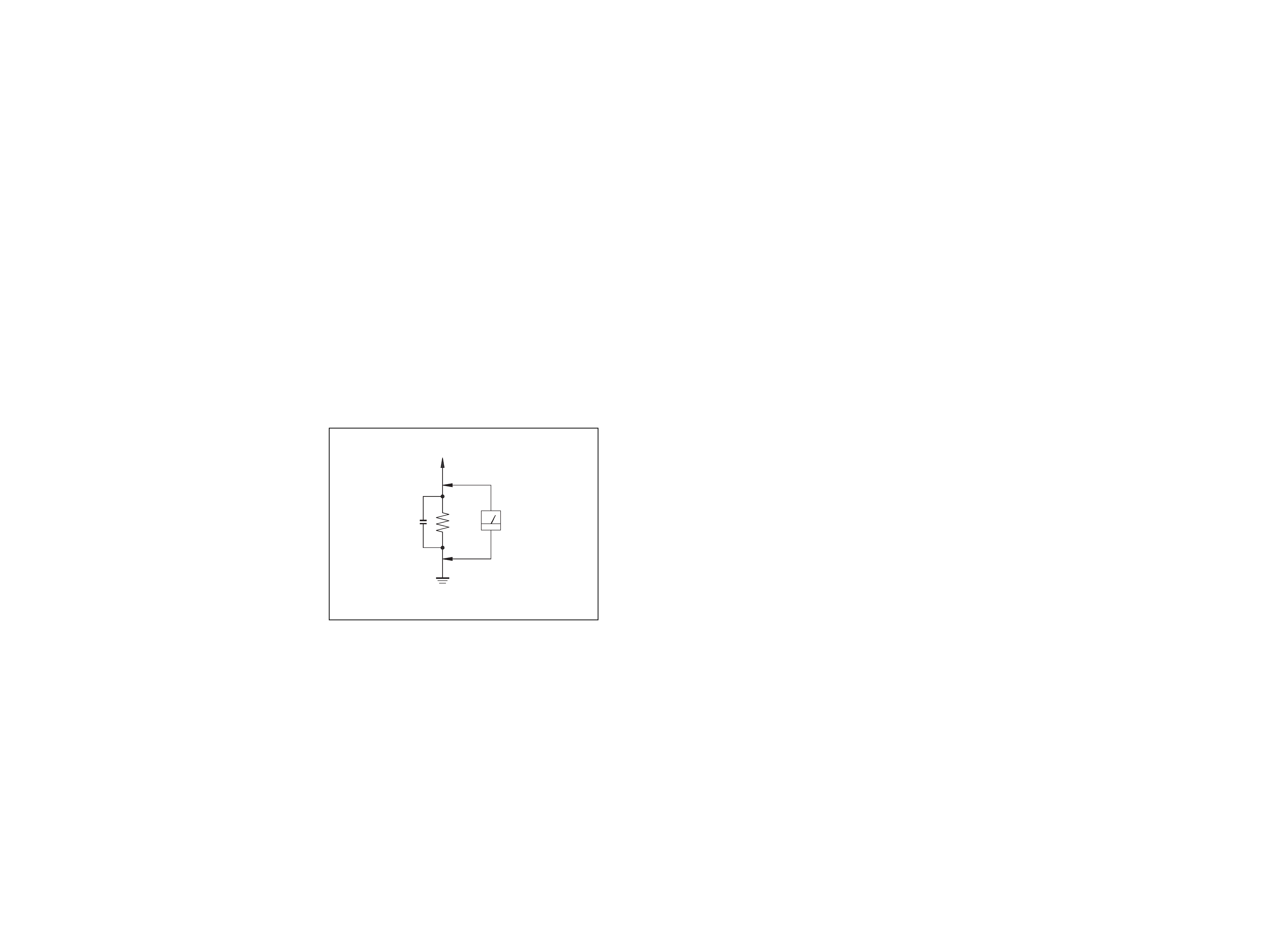
SAFETY CHECK-OUT
To Exposed Metal
Parts on Set
0.15
µF
1.5 k
AC
Voltmeter
(0.75 V)
Earth Ground
Fig. A. Using an AC voltmeter to check AC leakage.
2
3
SECTION 1
DIAGRAMS
1-1. NOTE FOR PRINTED WIRING BOARDS AND SCHEMATIC DIAGRAMS
Note on Printed Wiring Board:
· X : parts extracted from the component side.
· b : Pattern from the side which enables seeing.
· Indication of transistor.
B
These are omitted.
CE
Q
Note on Schematic Diagram:
· All capacitors are in
µF unless otherwise noted. pF: µµF
50 WV or less are not indicated except for electrolytics
and tantalums.
· All resistors are in
and 1/4 W or less unless otherwise
specified.
· 2 : nonflammable resistor.
· C : panel designation.
· U : B+ Line.
· V : B Line.
·Voltages are dc with respect to ground under no-signal
conditions.
no mark : AUDIO
·Voltages are taken with a VOM (input impedance 10 M
).
Voltage variations may be noted due to normal produc-
tion tolerances.
·Abbreviation
CND : Canadian model
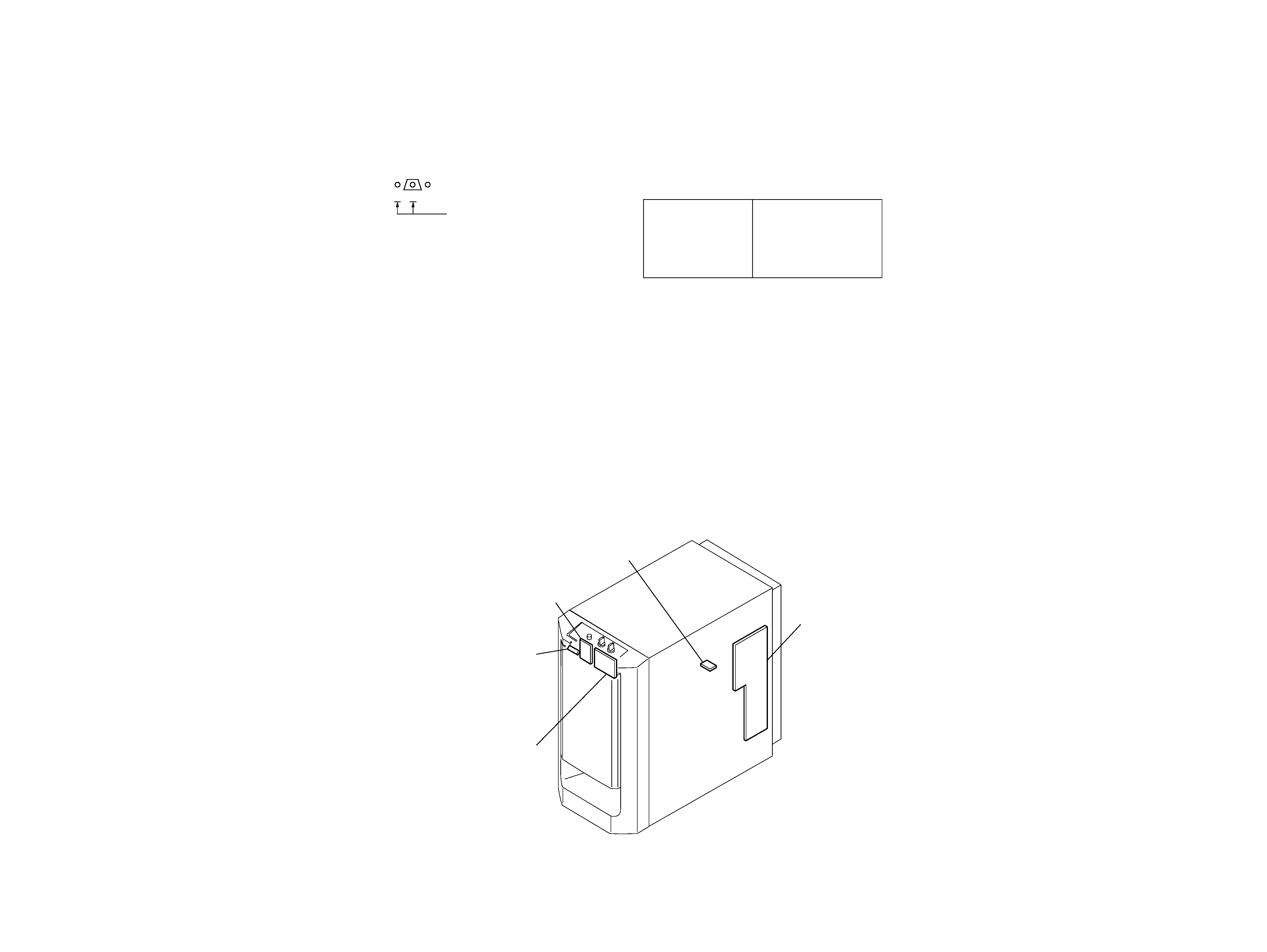
· Circuit Boards Location
SA-WMS315
Note:
The components identi-
fied by mark 0 or dotted
line with mark 0 are criti-
cal for safety.
Replace only with part
number specified.
Note:
Les composants identifiés par
une marque 0 sont critiques
pour la sécurité.
Ne les remplacer que par une
piéce por tant le numéro
spécifié.
POWER board
POWER SWITCH board
LED board
CONTROL board
MAIN board
4
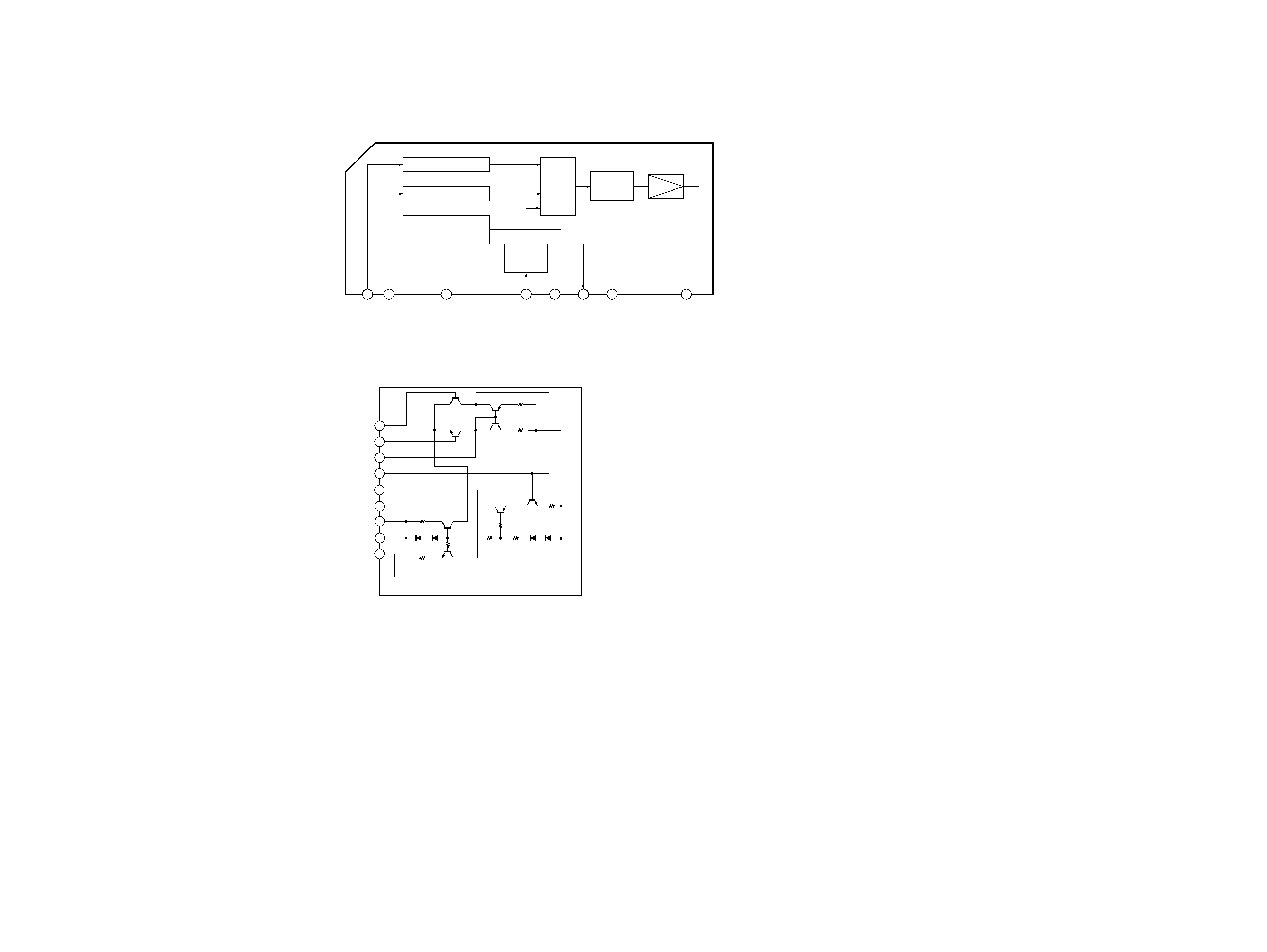
· IC Block Diagrams
IC302 uPC1237H
IC301 STK350-230
1
2
3
4
5
6
7
8
OVER LOAD DET
F/F
OFFSET DET
LATCH/
AUTORESET
VCC ON
MUTE
AC OFF
DET
VCC
1
2
3
4
5
6
7
8
9
TR3
R1
R2
TR4
TR6
TR7
R4
R9
TR5
TR1
TR2
R6
D4
D3
R7
R8
TR8
D1
D2
R5
R3
INPUT
NF
-VEOUT
+VEOUT
VSS
GND
VCC
SUB
SA-VE312/VE315/WMS315/SS-CN315/V315
5
5
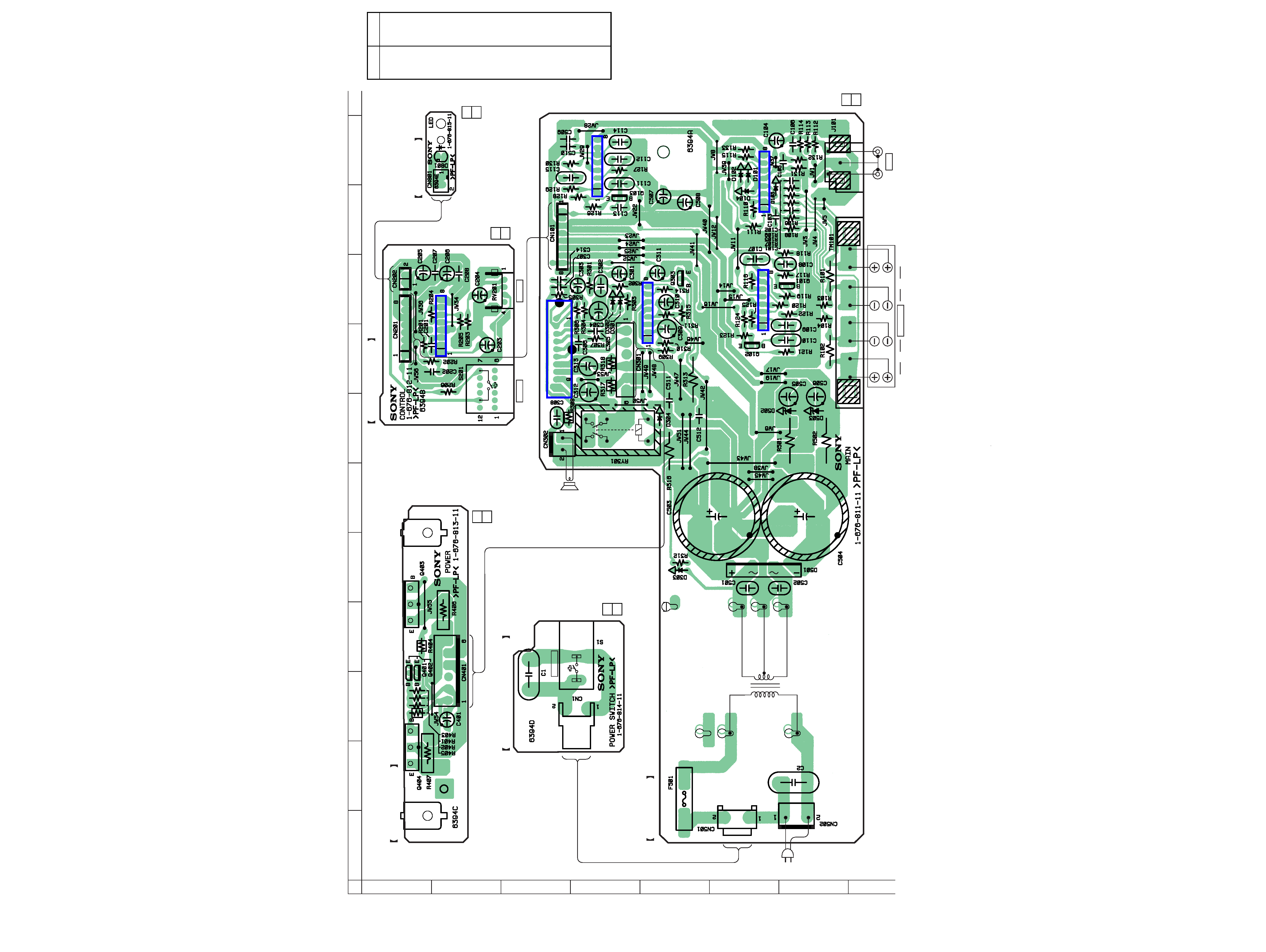
1-2. PRINTED WIRING BOARD (SA-WMS315)
(EXCEPT AEP,UK)
· See page 3 for Circuit Boards Location.
Ref. No.
Location
D101
F-11
D102
F-11
D103
F-11
D104
F-11
D301
D-8
D302
D-8
D303
E-5
D304
E-7
D501
G-5
D502
F-7
D503
G-7
D801
B-11
IC101
F-11
IC102
F-9
IC103
D-11
IC201
B-8
IC301
C-9
IC302
D-9
Q101
G-9
Q102
F-8
Q103
D-10
Q303
E-9
Q401
A-3
Q402
A-3
Q403
A-5
Q404
A-2
· Semiconductor
Location
IC103
IC302
IC102
IC101
IC201
IC301
11
(11)
11
(11)
11
(11)
11
(11)
11
(11)
POWER SWITCH BOARD
POWER BOARD
CONTROL BOARD
LED BOARD
MAIN BOARD
POWER
SPEAKER
LEVEL
MODE
LINE
T501
POWER
TRANSFORMER
R
L
OUT
IN
ON : MUSYC
OFF: MOVIE
(POWER)
SP1
(SPEAKER)
AC
IN
12
A
B
C
D
E
F
G
H
3456789
10
11
12
Ver 1.1 2004.01