Hyper HAD
TM
SERVICE MANUAL
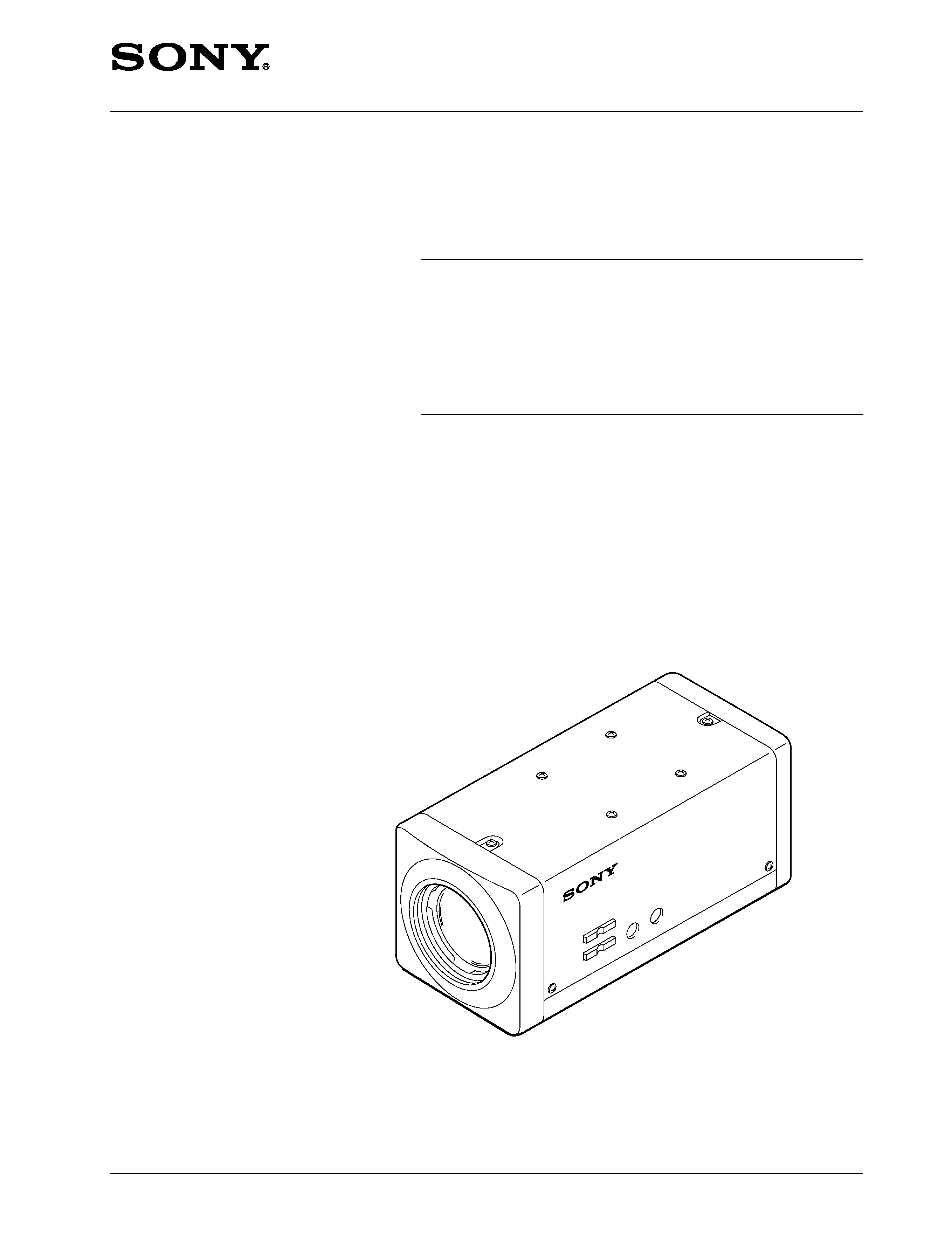
BLACK AND WHITE CAMERA
SSC-MX34
1st Edition

! WARNING
This manual is intended for qualified service personnel only.
To reduce the risk of electric shock, fire or injury, do not perform any servicing other than that
contained in the operating instructions unless you are qualified to do so. Refer all servicing to
qualified service personnel.
! WARNUNG
Die Anleitung ist nur für qualifiziertes Fachpersonal bestimmt.
Alle Wartungsarbeiten dürfen nur von qualifiziertem Fachpersonal ausgeführt werden. Um die
Gefahr eines elektrischen Schlages, Feuergefahr und Verletzungen zu vermeiden, sind bei
Wartungsarbeiten strikt die Angaben in der Anleitung zu befolgen. Andere als die angegeben
Wartungsarbeiten dürfen nur von Personen ausgeführt werden, die eine spezielle Befähigung
dazu besitzen.
! AVERTISSEMENT
Ce manual est destiné uniquement aux personnes compétentes en charge de l'entretien. Afin
de réduire les risques de décharge électrique, d'incendie ou de blessure n'effectuer que les
réparations indiquées dans le mode d'emploi à moins d'être qualifié pour en effectuer d'autres.
Pour toute réparation faire appel à une personne compétente uniquement.

1
SSC-CX34(UC)
TABLE OF CONTENTS
1. OPERATING INSTRUCTIONS
2. SERVICE INFORMATION
2-1. REMOVAL OF CCD ASSY ....................................................................... 2-1
2-2. EXTENSION HARNESS ............................................................................. 2-1
3. OPERATIONAL DESCRIPTION
3-1. BI-123 Board .................................................................................................. 3-1
3-2. PR-230 Board ................................................................................................. 3-1
3-3. IF-669 Board .................................................................................................. 3-1
3-4. PS-482 Board ................................................................................................. 3-2
3-5. CT-206 Board ................................................................................................. 3-2
3-6. AC-187 Board ................................................................................................ 3-2
4. ALIGNMENT
4-1. PREPARATIONS .......................................................................................... 4-1
4-1-1.
Equipment Required ............................................................................... 4-1
4-1-2.
Connection for Adjustment .................................................................... 4-2
4-1-3.
Adjustment Software .............................................................................. 4-3
4-1-4.
Adjustment Commander ......................................................................... 4-3
4-1-5.
Terminals to Determine Signals for Adjustment .................................... 4-4
4-1-6.
Chart to Select Items Requiring Adjustment .......................................... 4-4
4-2. ADJUSTMENT METHOD ........................................................................... 4-5
4-2-1.
Preparations for Adjustment ................................................................... 4-5
4-2-2.
Writing in Initial Data (PR Board) ......................................................... 4-5
4-2-3.
Writing in Initial Data (IF Board) .......................................................... 4-5
4-3. PRE ADJUSTMENT .................................................................................... 4-5
4-3-1.
Hall Adjustment ...................................................................................... 4-5
4-3-2.
Flange Back Adjustment ........................................................................ 4-5
4-3-3.
V-Shifter Offset Reading ........................................................................ 4-6
4-3-4.
VCO Adjustment .................................................................................... 4-6
4-4. CAMERA ADJUSTMENT ........................................................................... 4-6
4-4-1.
Setting up the Prepare for Adjustment Mode ......................................... 4-6
4-4-2.
VSUB and VPG Adjustment .................................................................. 4-7
4-4-3.
SYNC Level Adjustment ........................................................................ 4-8
4-4-4.
0 dB Adjustment ..................................................................................... 4-8
4-4-5.
AGC MAX Adjustment .......................................................................... 4-9
4-4-6.
Data Write .............................................................................................. 4-9
4-5. AFTER ADJUSTMENT CHECK .............................................................. 4-10
4-5-1.
Checking VSUB Voltage Adjustment .................................................. 4-10
4-5-2.
Checking VPG Voltage Adjustment .................................................... 4-10
4-5-3.
Checking SYNC Level Adjustment ..................................................... 4-10
4-5-4.
Checking SET UP Adjustment ............................................................. 4-10
4-5-5.
Checking 0 dB Adjustment .................................................................. 4-10

2
SSC-CX34(UC)
4-5-6.
Checking AGC Adjustment .................................................................. 4-11
5. SPARE PARTS
5-1. NOTES ON SPARE PARTS ......................................................................... 5-1
5-2. EXPLODED VIEW ....................................................................................... 5-2
5-3. ELECTRICAL PARTS LIST ......................................................................... 5-4
6. SEMICONDUCTOR PIN ASSIGNMENTS
DIODE ..................................................................................................................... 6-2
TRANSISTOR ........................................................................................................ 6-2
LED ........................................................................................................................ 6-2
IC
........................................................................................................................ 6-3
7. DIAGRAMS
7-1. BOARD LOCATION ..................................................................................... 7-1
7-2. BLOCK DIAGRAM ...................................................................................... 7-2
7-3. SCHEMATIC DIAGRAMS AND PRINTED CIRCUIT
BOARDS FRAME ......................................................................................... 7-4
1-1
SSC-MX34(UC)
SECTION 1
OPERATING INSTRUCTIONS
3-864-963-11 (1)
Sony Corporation
© 1998 Printed in Japan
Owner's Record
The model and serial numbers are located on the bottom.
Record these numbers in the spaces provided below.
Refer to these numbers whenever you call upon your Sony dealer
regarding this product.
Model No.
Serial No.
SSC-MX34
Black and White
Video Camera
Operating Instructions
Before operating the unit, please read these instructions
thoroughly and retain them for future reference.
Mode d'emploi
Avant de faire fonctionner cet appareil, lisez attentivement le
présent mode d'emploi et conservez-le pour toute référence
ultérieure.
Manual de instrucciones
Antes de utilizar la unidad, lea las instrucciones con atención y
consérvelas para su consulta en el futuro.
The glaphical simbol is on the unit.
This symbol is intended to alert the user to the
presence of important operating and maintenance
(servicing) instructions in the literature accompanying
the appliance.
WARNING
To prevent fire or shock hazard, do not expose
the unit to rain or moisture.
To avoid electrical shock, do not open the cabi-
net. Refer servicing to qualified personnel only.
For the customers in the U.S.A.
This equipment has been tested and found to comply with the limits for
a Class B digital device, pursuant to Part 15 of the FCC Rules. These
limits are designed to provide reasonable protection against harmful
interference in a residential installation. This equipment generates,
uses, and can radiate radio frequency energy and, if not installed
and used in accordance with the instructions, may cause harmful
interference to radio communications. However, there is no guarantee
that interference will not occur in a particular installation. If this equip-
ment does cause harmful interference to radio or television reception,
which can be determined by turning the equipment off and on, the user
is encouraged to try to correct the interference by one or more of the
following measures:
· Reorient or relocate the receiving antenna.
· Increase the separation between the equipment and receiver.
· Connect the equipment into an outlet on a circuit different from that to
which the receiver is connected.
· Consult the dealer or an experienced radio/TV technician for help.
This device requires shielded interface cable to comply with FCC
emission limits.
You are cautioned that any changes or modifications not expressly
approved in this manual could void your authority to operate this
equipment.
AVERTISSEMENT
Afin d'éviter tout risque d'incendie ou d'electrocution, ne
pas exposer cet appareil à la pluie ou à l'humidité.
Afin d'écarter tout risque d'électrocution, garder le coffret
fermé. Ne confier l'entretien de l'appareil qu'à un personnel
qualifié.
ADVERTENCIA
Para evitar incendios o el riesgo de electrocución, no
exponga la unidad a la lluvia ni a la humedad.
Para evitar descargas eléctricas, no abra la caja.
En caso de avería, solicite asistencia técnica a personal
cualificado.
This section is extracted
from operation manual.
http://getMANUAL.com