HD DIGITAL VIDEOCASSETTE RECORDER
SRW-5000
SRW-5500
FORMAT CONVERTER BOARD
HKSR-5001
DIGITAL BETACAM PROCESSOR BOARD
HKSR-5002
RGB PROCESSOR BOARD
HKSR-5003
OPERATION MANUAL
[English]
1st Edition (Revised 4)

2
· Read these instructions.
· Keep these instructions.
· Heed all warnings.
· Follow all instructions.
· Do not use this apparatus near water.
· Clean only with dry cloth.
· Do not block any ventilation openings.
Install in accordance with the manufacturer's
instructions.
· Do not install near any heat sources such as radiators,
heat registers, stoves, or other apparatus (including
amplifiers) that produce heat.
· Do not defeat the safety purpose of the polarized or
grounding-type plug. A polarized plug has two blades
with one wider than the other. A grounding-type plug
has two blades and a third grounding prong. The wide
blade or the third prong are provided for your safety. If
the provided plug does not fit into your outlet, consult an
electrician for replacement of the obsolete outlet.
· Protect the power cord from being walked on or pinched
particularly at plugs, convenience receptacles, and the
point where they exit from the apparatus.
· Only use attachments/accessories specified by the
manufacturer.
· Use only with the cart, stand, tripod, bracket,
or table specified by the manufacturer, or sold
with the apparatus.
When a cart is used, use caution when moving
the cart/apparatus combination to avoid injury from tip-
over.
· Unplug this apparatus during lightning storms or when
unused for long periods of time.
· Refer all servicing to qualified service personnel.
Servicing is required when the apparatus has been
damaged in any way, such as power-supply cord or plug
is damaged, liquid has been spilled or objects have fallen
into the apparatus, the apparatus has been exposed to
rain or moisture, does not operate normally, or has been
dropped.
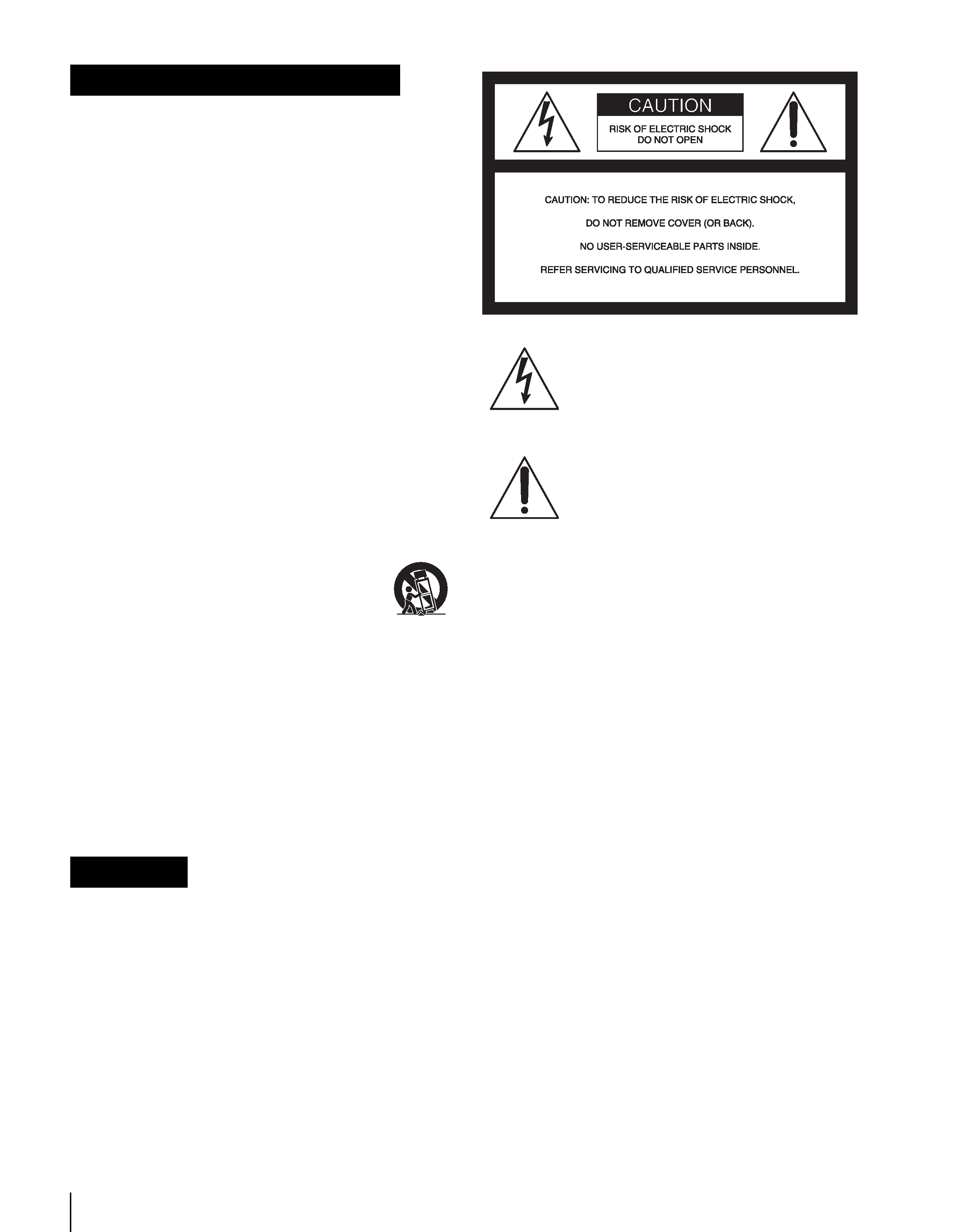
To prevent fire or shock hazard, do not
expose the unit to rain or moisture.
To avoid electrical shock, do not open the
cabinet. Refer servicing to qualified
personnel only.
THIS APPARATUS MUST BE EARTHED.
WARNING: THIS WARNING IS APPLICABLE
FOR USA ONLY.
If used in USA, use the UL LISTED power
cord specified below.
DO NOT USE ANY OTHER POWER
CORD.
Plug Cap
Parallel Blade with ground pin
(NEMA 5-15P Configuration)
Cord
Type SJT, three 16 or 18 AWG
wires
Length
Minimum 1.5 m (4 ft 11 in), less
than 2.5 m (8 ft 3 in)
Rating
Minimum 10 A, 125 V
Using this unit at a voltage other than 120 V
may require the use of a different line cord
or attachment plug, or both. To reduce the
risk of fire or electric shock, refer servicing
to qualified service personnel.
WARNING: THIS WARNING IS APPLICABLE
FOR OTHER COUNTRIES.
1. Use the approved Power Cord (3-core mains lead)/
Appliance Connector/Plug with earthing-contacts that
conforms to the safety regulations of each country if
applicable.
2. Use the Power Cord (3-core mains lead)/Appliance
Connector/Plug conforming to the proper ratings
(Voltage, Ampere).
Important Safety Instructions
WARNING
This symbol is intended to alert the user to
the presence of uninsulated "dangerous
voltage" within the product's enclosure
that may be of sufficient magnitude to
constitute a risk of electric shock to
persons.
This symbol is intended to alert the user to
the presence of important operating and
maintenance (servicing) instructions in
the literature accompanying the
appliance.

3
If you have questions on the use of the above Power Cord/
Appliance Connector/Plug, please consult a qualified
service personnel.
CAUTION
The apparatus shall not be exposed to dripping or
splashing and no objects filled with liquid, such as vases,
shall be placed on the apparatus.
CAUTION
The unit is not disconnected from the AC power source
(mains) as long as it is connected to the wall outlet, even if
the unit itself has been turned off.
For the customers in U.S.A.
This equipment has been tested and found to comply with
the limits for a Class A digital device, pursuant to Part 15
of the FCC Rules. These limits are designed to provide
reasonable protection against harmful interference when
the equipment is operated in a commercial environment.
This equipment generates, uses, and can radiate radio
frequency energy and, if not installed and used in
accordance with the instruction manual, may cause
harmful interference to radio communications. Operation
of this equipment in a residential area is likely to cause
harmful interference in which case the user will be
required to correct the interference at his own expense.
You are cautioned that any changes or modifications not
expressly approved in this manual could void your
authority to operate this equipment.
The shielded interface cable recommended in this manual
must be used with this equipment in order to comply with
the limits for a digital device pursuant to Subpart B of Part
15 of FCC Rules.
For the customers in the U.S.A.
This product contains mercury. Disposal of this product
may be regulated if sold in the U.S.A. For disposal or
recycling information, please contact your local authorities
or the Electronics Industries Alliance
(www.eiae.org http://www.eiae.org ).
Do not install the appliance in a confined space, such as
book case or built-in cabinet.
For the customers in Europe
This product with the CE marking complies with both the
EMC Directive (89/336/EEC) and the Low Voltage
Directive (73/23/EEC) issued by the Commission of the
European Community.
Compliance with these directives implies conformity to
the following European standards:
· EN60065: Product Safety (For SRW-5000/5500)
· EN55103-1: Electromagnetic Interference (Emission)
· EN55103-2: Electromagnetic Susceptibility (Immunity)
This product is intended for use in the following
Electromagnetic Environment(s):
E1 (residential), E2 (commercial and light industrial), E3
(urban outdoors), E4 (controlled EMC environment, ex.
TV studio).

4
Table of Contets
Table of Contents
Chapter 1 Overview
1-1 Features ........................................................................... 9
1-1-1 Features of the SRW-5000/SRW-5500.............................9
1-1-2 Features of the Control Panel..........................................11
1-2 Optional Accessories ................................................... 13
1-3 Using the CD-ROM Manual .......................................... 13
1-3-1 CD-ROM System Requirements.....................................13
1-3-2 Preparations.....................................................................13
1-3-3 To Read the CD-ROM Manual.......................................13
Chapter 2 Locations and Functions of Parts
2-1 Control Panel................................................................. 15
2-1-1 Upper Control Panel .......................................................16
2-1-2 Lower Control Panel .......................................................17
2-1-3 System Set-Up Panel.......................................................23
2-2 Connector Panel ........................................................... 24
Chapter 3 Setting Up the VTR
3-1 Connecting External Equipment ................................. 29
3-1-1 Making HD Digital Connections ....................................29
3-1-2 Making NTSC/PAL Digital Connections .......................30
3-1-3 Cascade Connection........................................................31
3-2 Reference Signals......................................................... 32
3-2-1 Reference Signals for Output Video ...............................32
3-2-2 Reference Signal Connections ........................................33
3-3 Handling Cassettes....................................................... 34
3-3-1 Recommended Cassettes.................................................34
3-3-2 Inserting and Ejecting Cassettes .....................................34
3-3-3 Preventing Accidental Erasure........................................35
3-4 Using a Memory Stick................................................... 35
3-4-1 Notes on Memory Stick ..................................................35

5
Table of Contets
Chapter 4 Menu Settings
4-1 Registering and Storing Menu Settings ......................37
4-1-1 Menu Configuration ........................................................37
4-1-2 Changing Menu Settings .................................................37
4-1-3 Registering Items to the VTR SETUP Menu..................38
4-1-4 VTR Memory Bank Function .........................................39
4-1-5 Memory Stick Operations ...............................................41
4-1-6 Adding Titles to the Data ................................................46
4-1-7 Details on VTR Memory Bank and Memory Stick
Functions .........................................................................46
4-1-8 Memory Stick Data Compatibility ..................................47
4-1-9 Automatic Reading from a VTR Bank at Power On.......47
4-1-10 Saving and Recalling DEFAULT Settings on a Bank ..48
4-1-11 Saving and Recalling DEFAULT Settings in a "Memory
Stick" ...............................................................................48
4-2 HOME Menu ...................................................................50
4-2-1 Selecting the Output Signals (PB/EE).............................51
4-2-2 Record Inhibit Mode (REC INH)....................................51
4-2-3 Selecting the Edit Mode and Edit Channel (ASSEMBLE,
INS TC, INS VIDEO, INS AUDIO and INS CUE)........51
4-2-4 Preread Settings (PRE READ)........................................52
4-2-5 Still-Picture Output (FREEZE) .......................................52
4-2-6 Setting the Preroll Time (PREROLL TIME) ..................52
4-2-7 Selecting DMC Playback (DMC) ...................................52
4-2-8 Setting the Stop Code (STOP CODE) ............................53
4-3 TC Menu .........................................................................56
4-3-1 Setting the Time Data (TIMER SEL/RESET/SET/HOLD)
57
4-3-2 Setting the Time Code Reader (TCR SEL).....................60
4-3-3 Setting the Time Code Generator (TCG SOURCE/MODE)
60
4-3-4 Selecting the Time Code Running Mode (RUN MODE) ...
60
4-3-5 Selecting the Drop Frame Mode (DF/NDF) ...................61
4-3-6 Selecting the Content of the Second Time Code Display
Area (TC2 SEL) ..............................................................61
4-3-7 Selecting CTL Display Mode (TAPE TIMER) ..............61
4-3-8 Presetting Pulldown Time Code (PDPSET MENU)
(when HKSR-5001 is installed) ......................................61
4-3-9 Presetting for Conversion from Frame Time Code
(TCCONV MENU) .........................................................62
4-3-10 Displaying the Pulldown Time Code (PDTC DISP) (when
HKSR-5001 is installed) .................................................64
