SRS-Z500/Z500PC
US Model
Canadian Model
AEP Model
UK Model
E Model
Australian Model
SRS-Z500/Z500PC
Tourist Model
SRS-Z500
SERVICE MANUAL
STEREO ACTIVE SPEAKER SYSTEM
MICROFILM
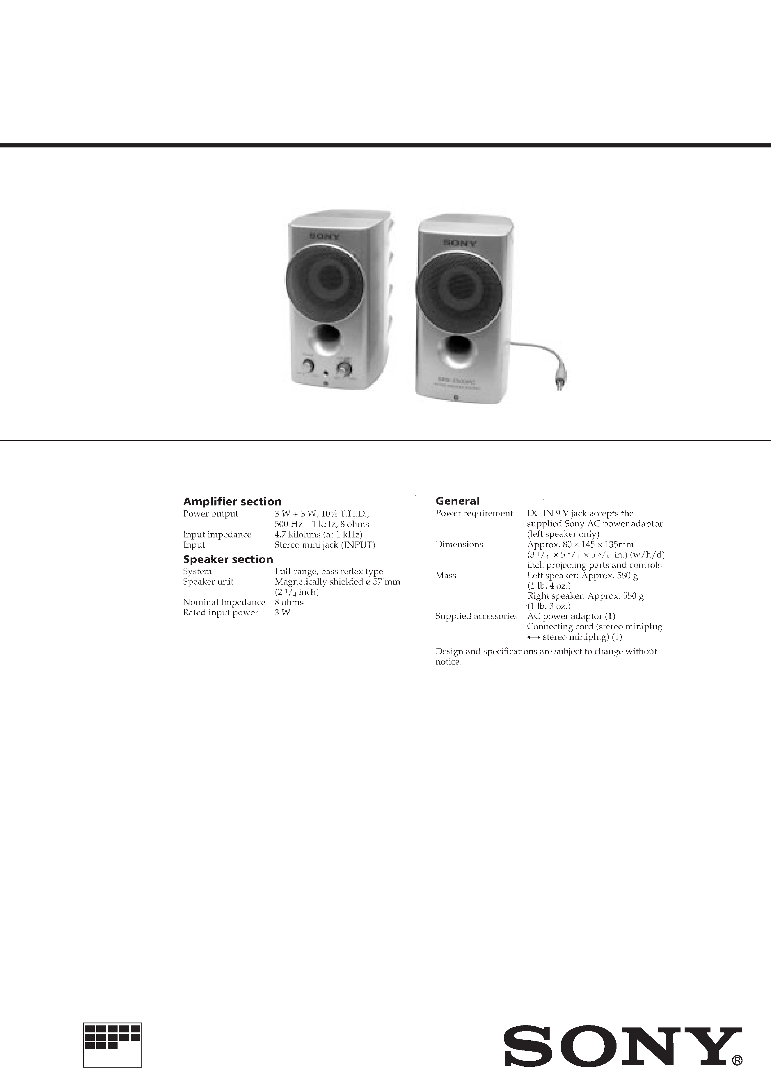
SPECIFICATIONS
Photo : SRS-Z500PC
Ver. 1.0
1998.9
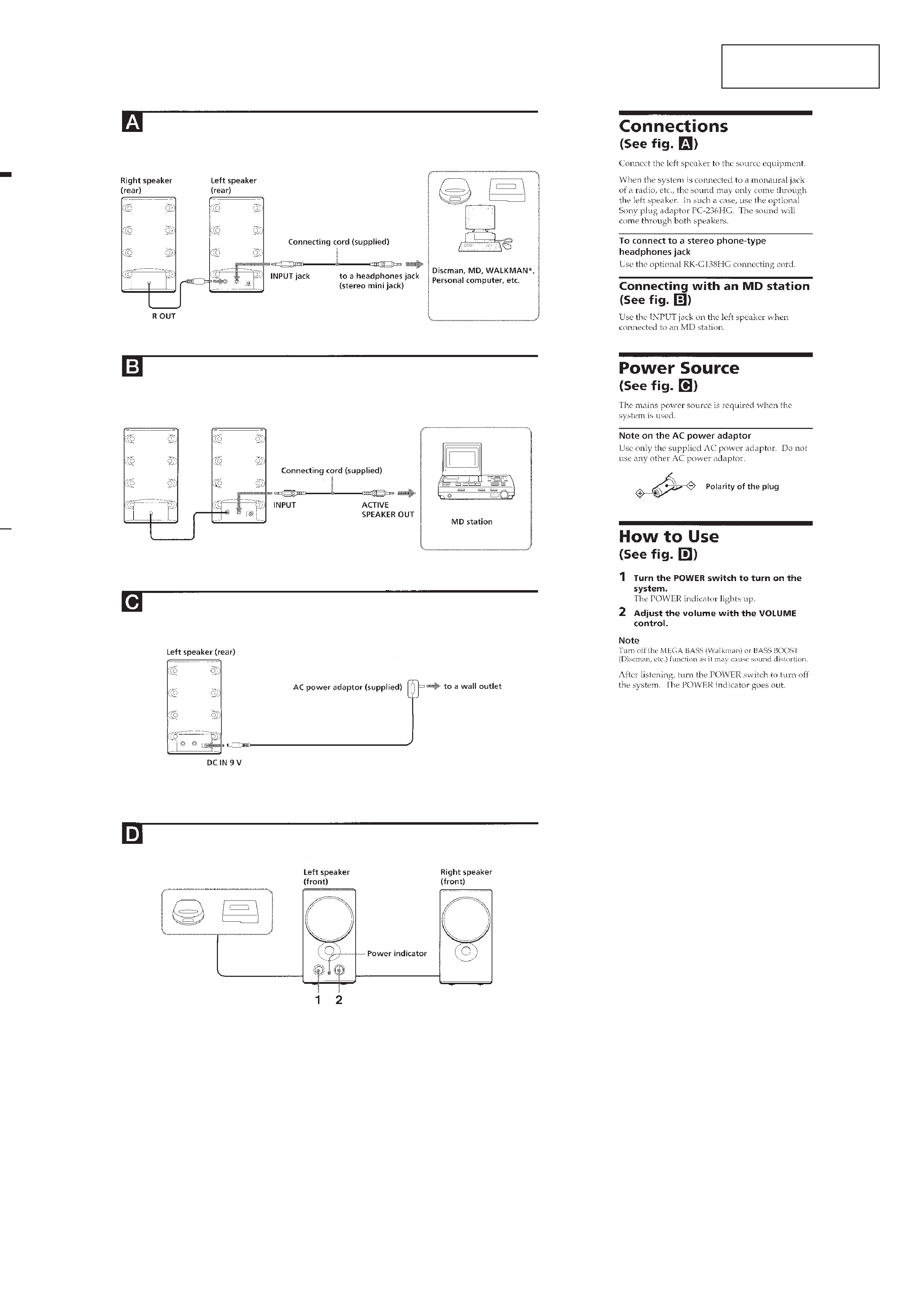
SECTION 1
GENERAL
-- 2 --
This section is extracted
from instruction manual.
SECTION 2
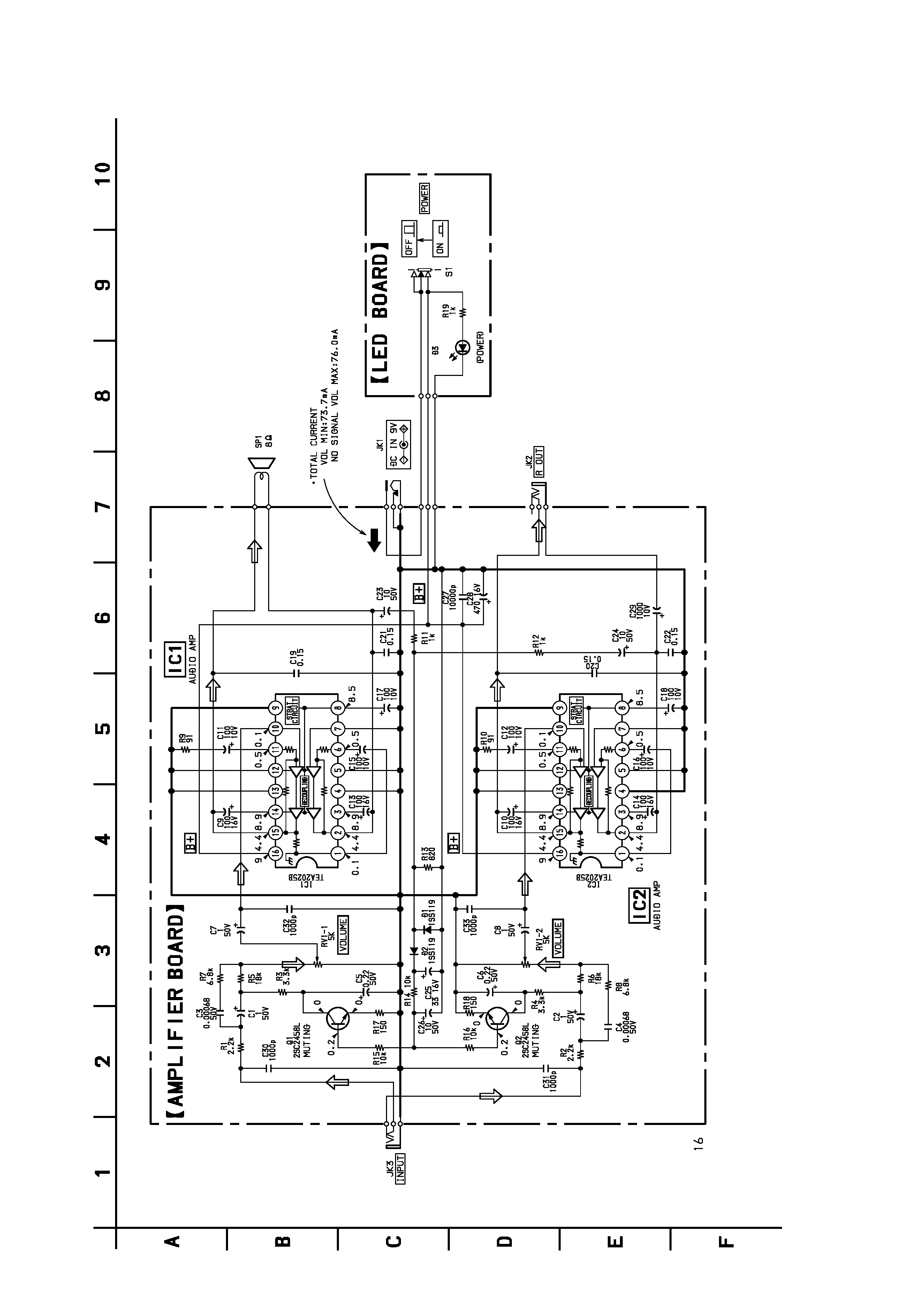
DIAGRAMS
2-1. SCHEMATIC DIAGRAM
-- 3 --
-- 4 --
SRS-Z500/Z500PC
Note on Schematic Diagram:
· All capacitors are in µF unless otherwise noted. pF: µµF
50 WV or less are not indicated except for electrolytics
and tantalums.
· All resistors are in
and 1/4 W or less unless otherwise
specified.
·
%
: indicates tolerance.
· C : panel designation.
· U : B+ Line.
204GD
· Power voltage is dc 9 V and fed with regulated dc power supply
from external power voltage jack.
· Voltages and waveforms are dc with respect to ground under no-
signal (detuned) conditions.
· Voltages are taken with a VOM (Input impedance 10 M
).
Voltage variations may be noted due to normal production toler-
ances.
· Signal path.
F
: AUDIO
-- 5 --
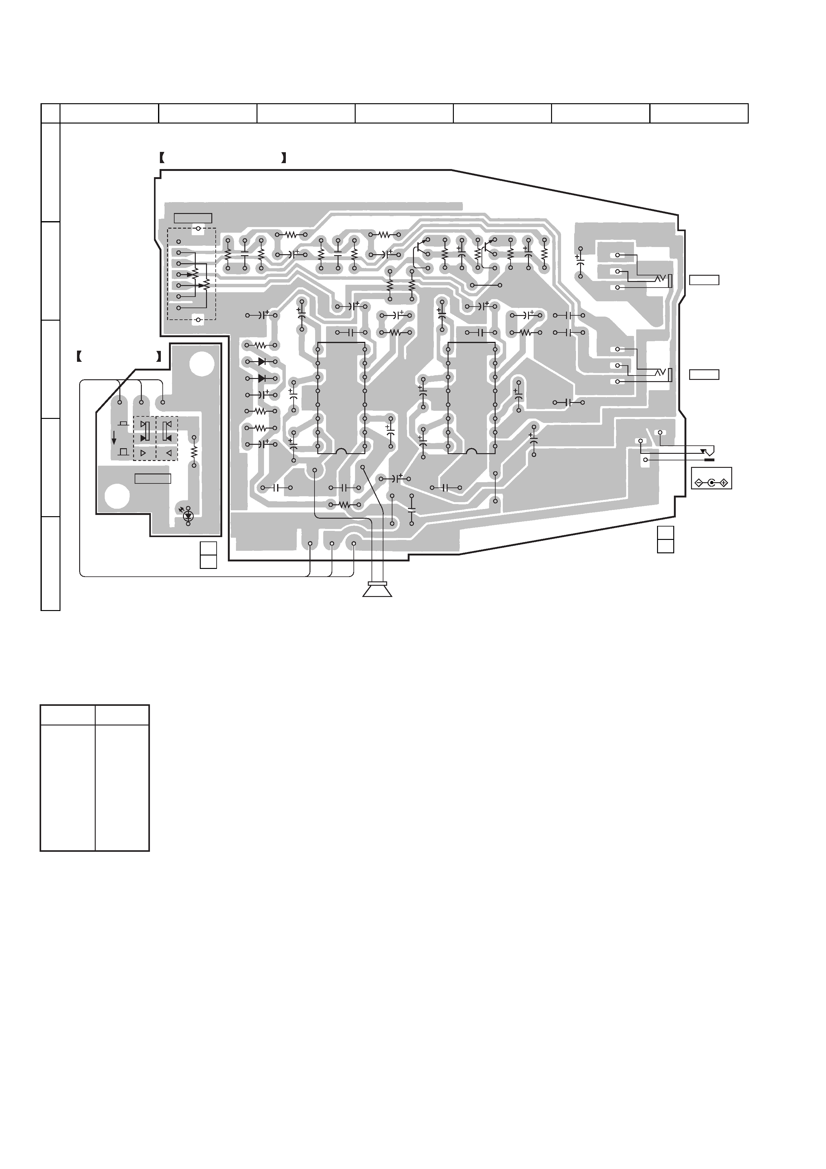
2-2. PRINTED WIRING BOARD
Note on Printed Wiring Board:
· X : parts extracted from the component side.
· b : Pattern from the side which enables seeing.
SRS-Z500/Z500PC
Ref. No. Location
D1
C-3
D2
C-3
D3
E-2
IC1
C-3
IC2
C-5
Q1
B-4
Q2
B-5
· Semiconductor
Location
DC IN 9V
11
(11)
11
(11)
ON
OFF
JK1
JK3
INPUT
JK2
R OUT
RV1
VOLUME
S1
POWER
(POWER)
C31
C29
C6
C5
C3
C17
C15
8
5
9
1
16
12
C13
C27
C14
C16
C10
C28
C9
R19
D3
C18
R4
R18
R17
R16
R15
R5
R7
C4
R6
R8
R3
Q2
Q1
C30
C20
C12
C11
C7
C32
C2
C26
C1
C8
C33
R10
R9
R1
R2
-2
-1
R14
R13
R11
R12
C23
C24
C21
C19
C22
C25
D2
D1
RED BLK
YEL
RED
RED
WHT
BLK
YEL
1-670-677-
SP1
IC1
8
5
9
1
16
12
IC2
1-670-676-
AMPLIFIER BOARD
LED BOARD
12
A
B
C
D
E
34567
-- 6 --
SECTION 3
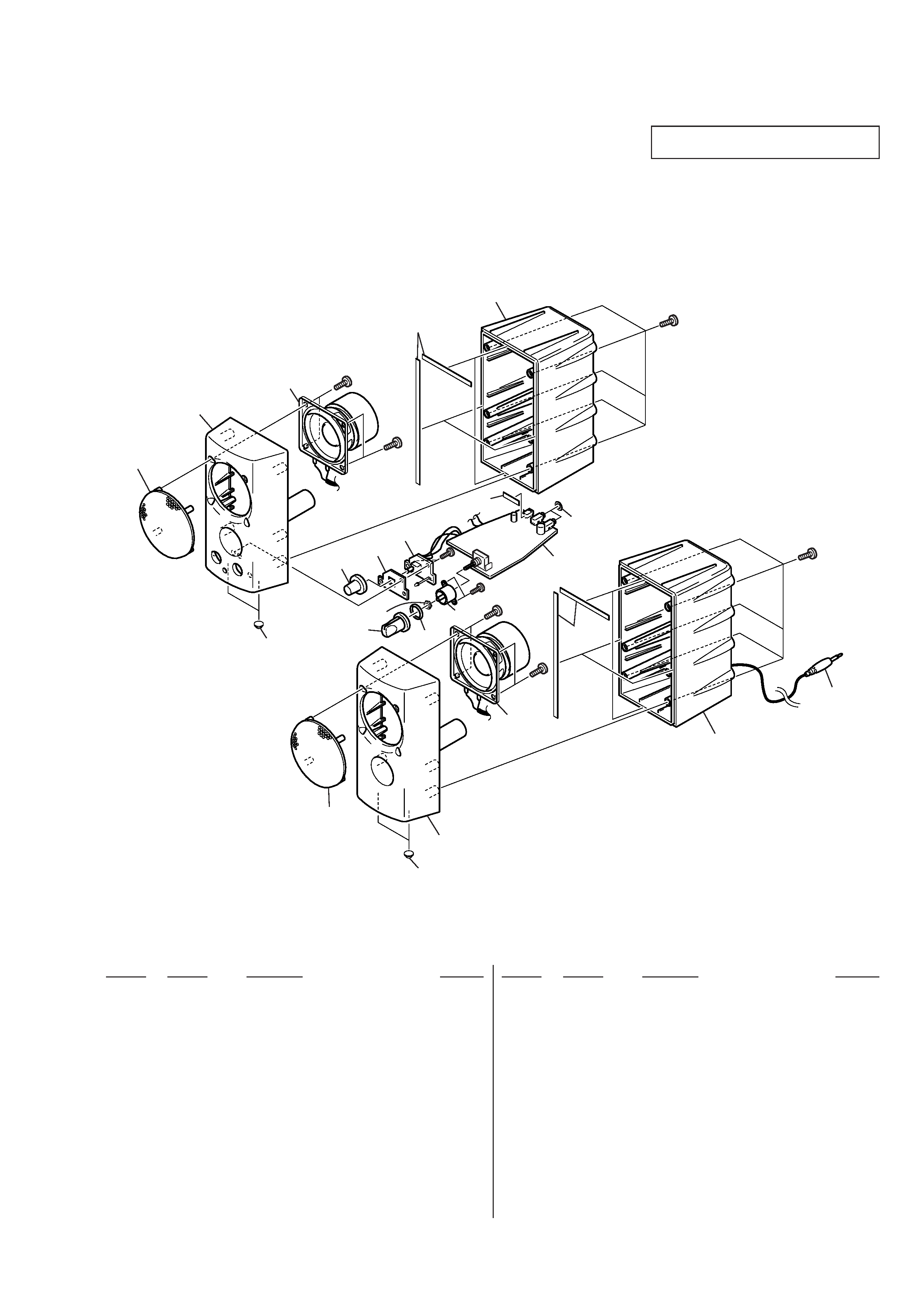
EXOPLODED VIEW
NOTE:
·
-XX, -X mean standardized parts, so they may
have some differences from the original one.
·
Items marked "*" are not stocked since they
are seldom required for routine service. Some
delay should be anticipated when ordering these
items.
·
The mechanical parts with no reference number
in the exploded views are not supplied.
·
Hardware (# mark) list and accessories and
packing materials are given in the last of this
parts list.
When indicating parts by reference number,
please include the board name.
Ref. No.
Part No.
Description
Remarks
Ref. No.
Part No.
Description
Remarks
1
2
3
4
3
3
5
3
13
14
15
9
9
1
10
8
7
6
11
12
SP1
SP2
#1
#1
#2
#2
#1
#1
#3
#3
Supplied with RV1
1
X-4950-285-1 GRILLE ASSY (Z500)
1
X-4950-436-1 GRILLE ASSY (Z500PC)
2
4-211-620-01 CABINET (L), FRONT (Z500)
2
4-211-620-11 CABINET (L), FRONT (Z500PC)
3
3-831-441-99 CUSHION
4
4-211-621-01 CABINET (L), REAR (Z500)
4
4-211-621-11 CABINET (L), REAR (Z500PC)
* 5
A-4542-548-A AMPLIFIER BOARD,COMPLETE
* 6
1-670-677-11 LED BOARD
7
4-213-000-01 CUSHION (LEDM'T)
8
4-211-625-01 BUTTON (POWER)(Z500)
8
4-211-625-11 BUTTON (POWER)(Z500PC)
9
3-740-607-01 CUSHION
10
4-211-627-01 KNOB (VOLUME) (Z500)
10
4-211-627-11 KNOB (VOLUME) (Z500PC)
11
4-212-999-01 CUSHION, VOLUME
12
4-211-624-01 HOLDER, VOLUME
13
1-769-080-11 CORD (WITH PLUG) (Z500)
13
1-769-080-31 CORD (WITH PLUG) (Z500PC)
14
4-211-629-01 CABINET (R), REAR (Z500)
14
4-211-629-11 CABINET (R), REAR (Z500PC)
15
4-211-628-01 CABINET (R), FRONT (Z500)
15
4-211-628-11 CABINET (R), FRONT (Z500PC)
SP1
1-529-138-11 SPEAKER (057F016)
SP2
1-529-138-11 SPEAKER (057F016)